A view itself is the workspace where the model or its part is rendered in a required projection. At the same time, several views can be activated. Adjusting settings of the views can be done simultaneously or separately. When working with the TS models you should, first of all, get a clear understanding of the fact that an open model might have no views, which does not mean that the model is empty.
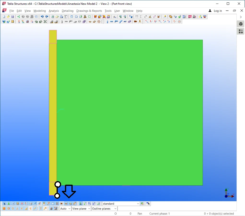
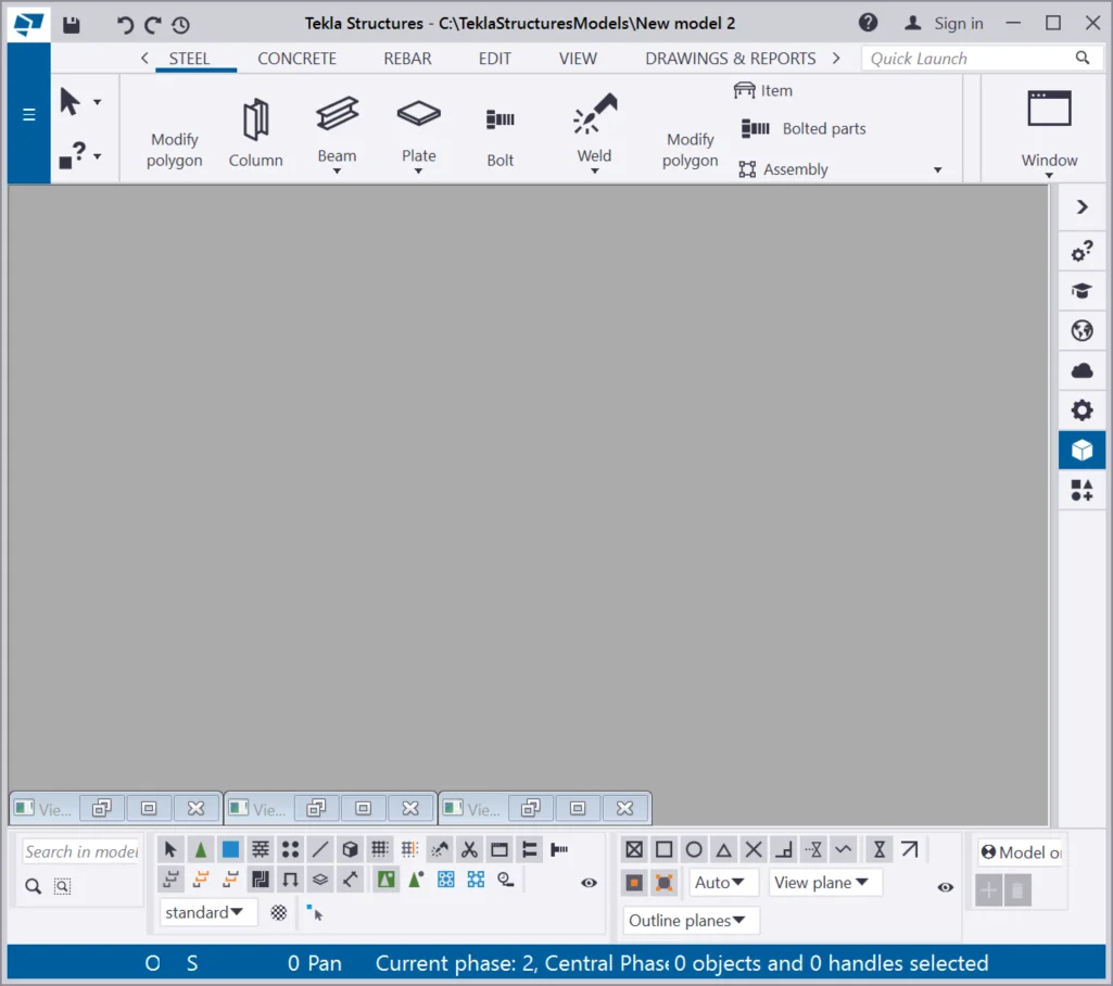
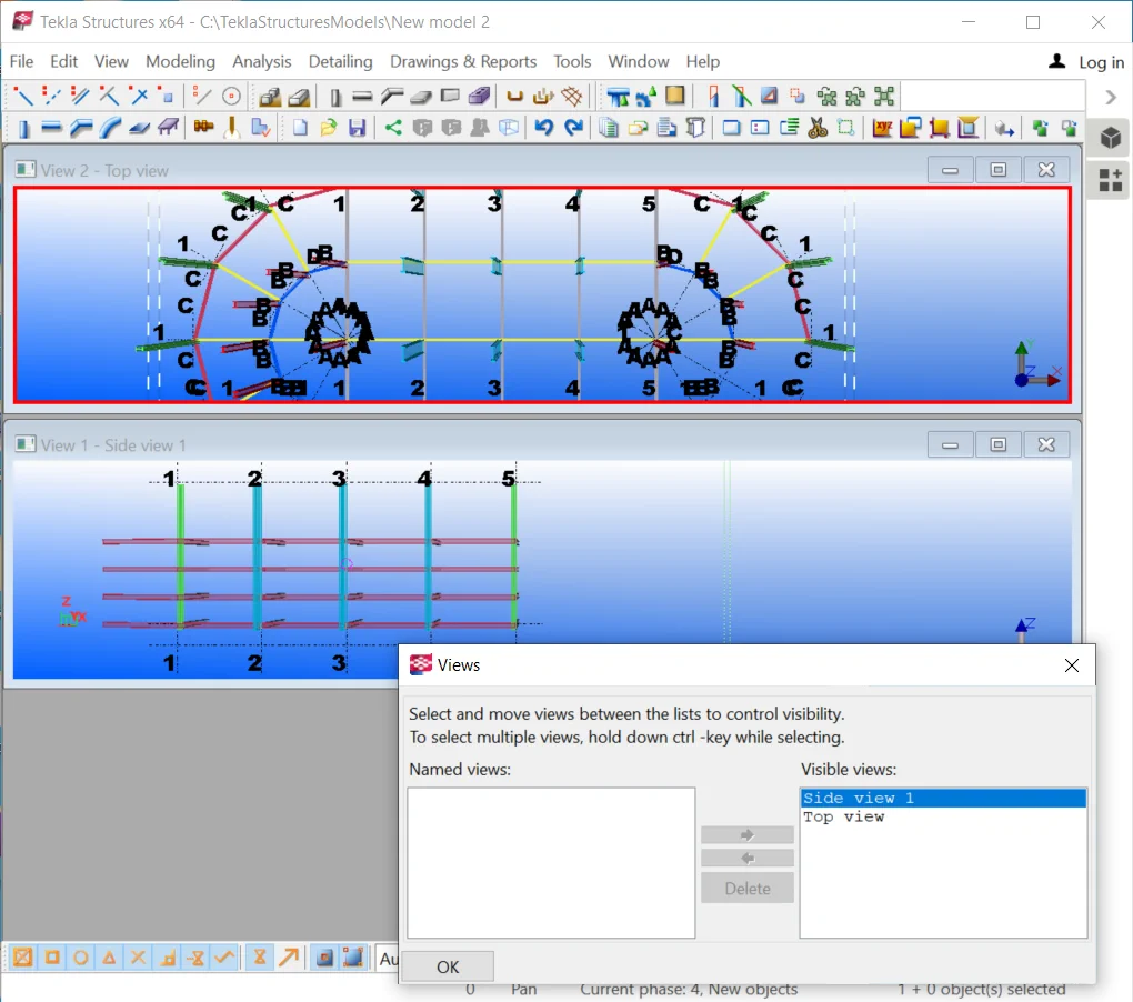
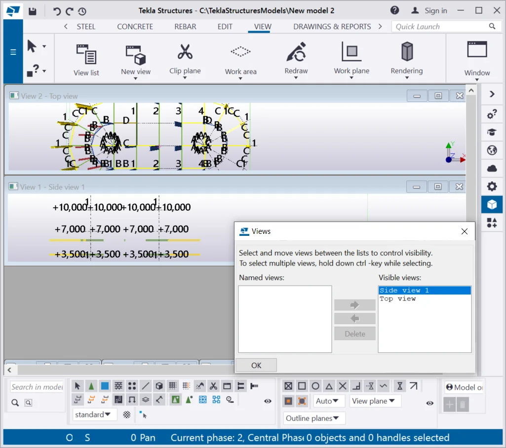
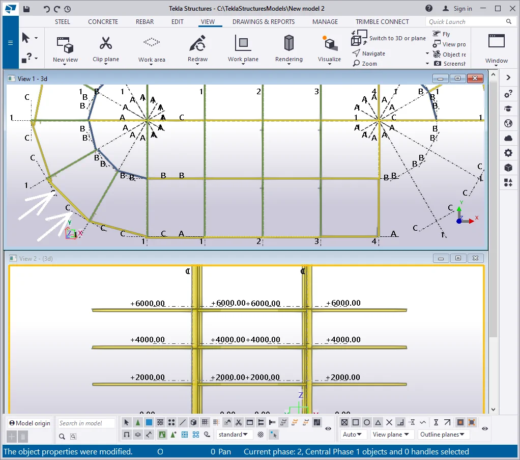
Now intentionally close all the views of the model. Refer to the below:

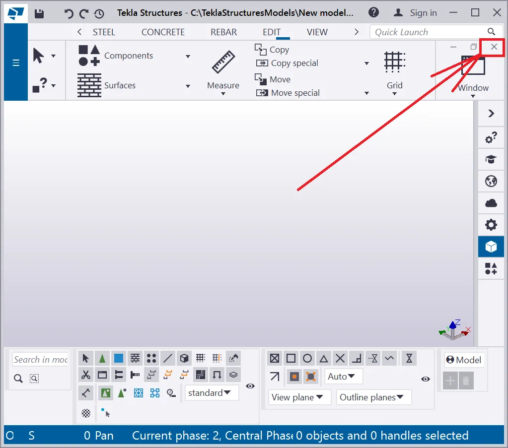
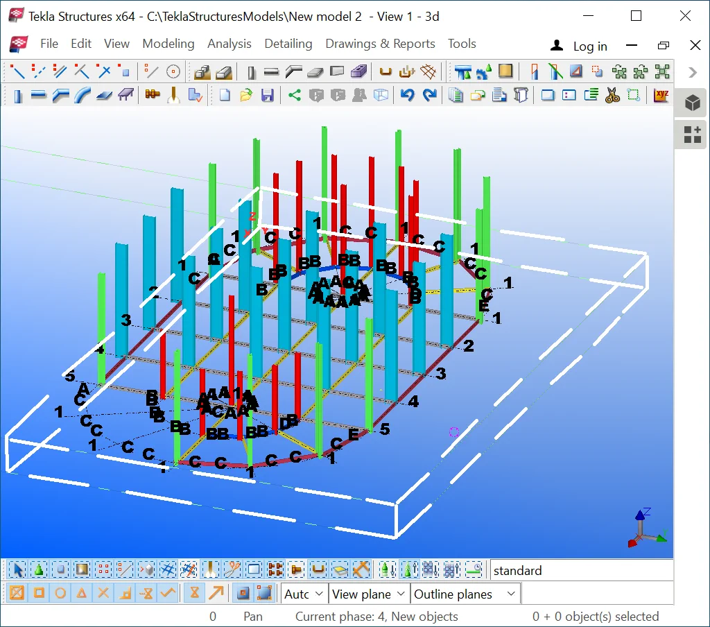
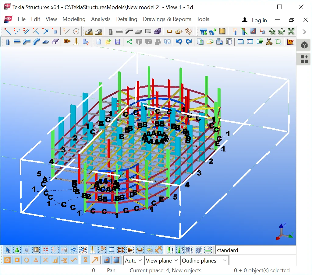
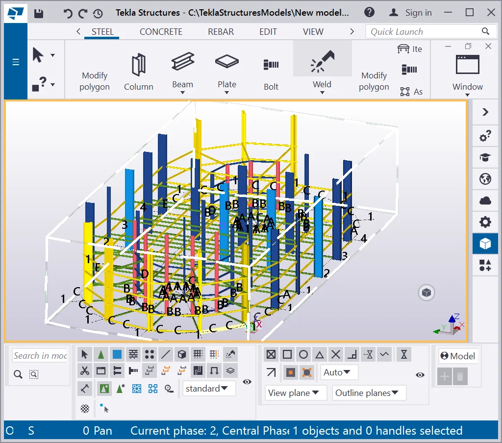
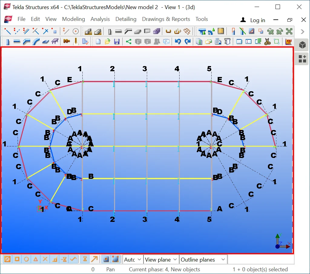
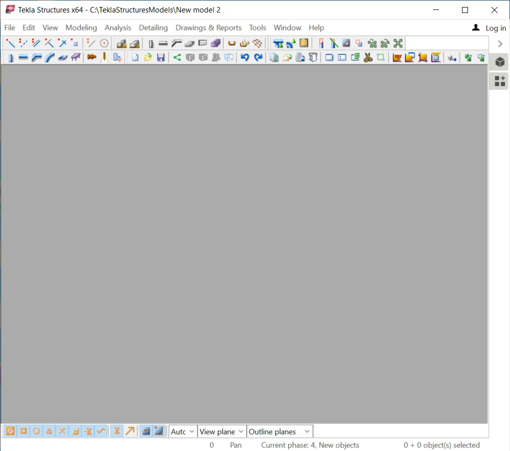
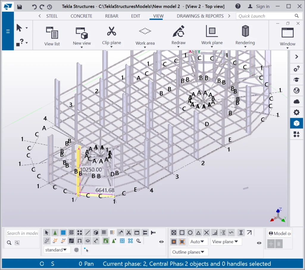
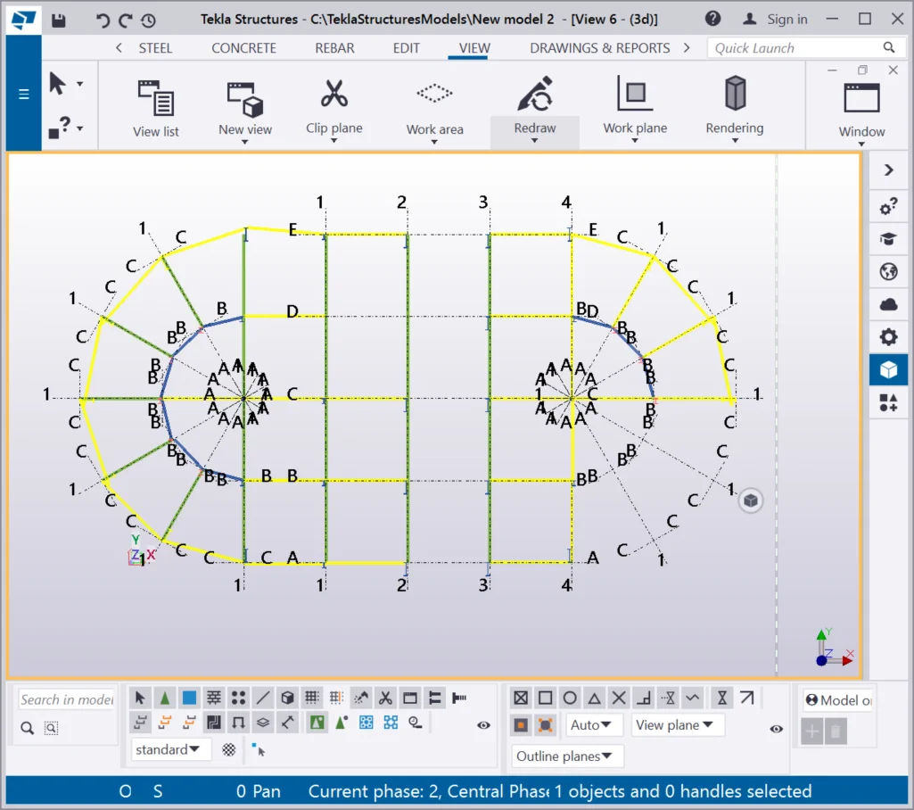
In most cases, when opening a project created by another user, you might see that the editor looks just like in the picture below. But it does not mean that the file is empty. There are just no views in it.
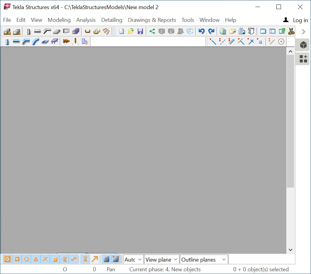

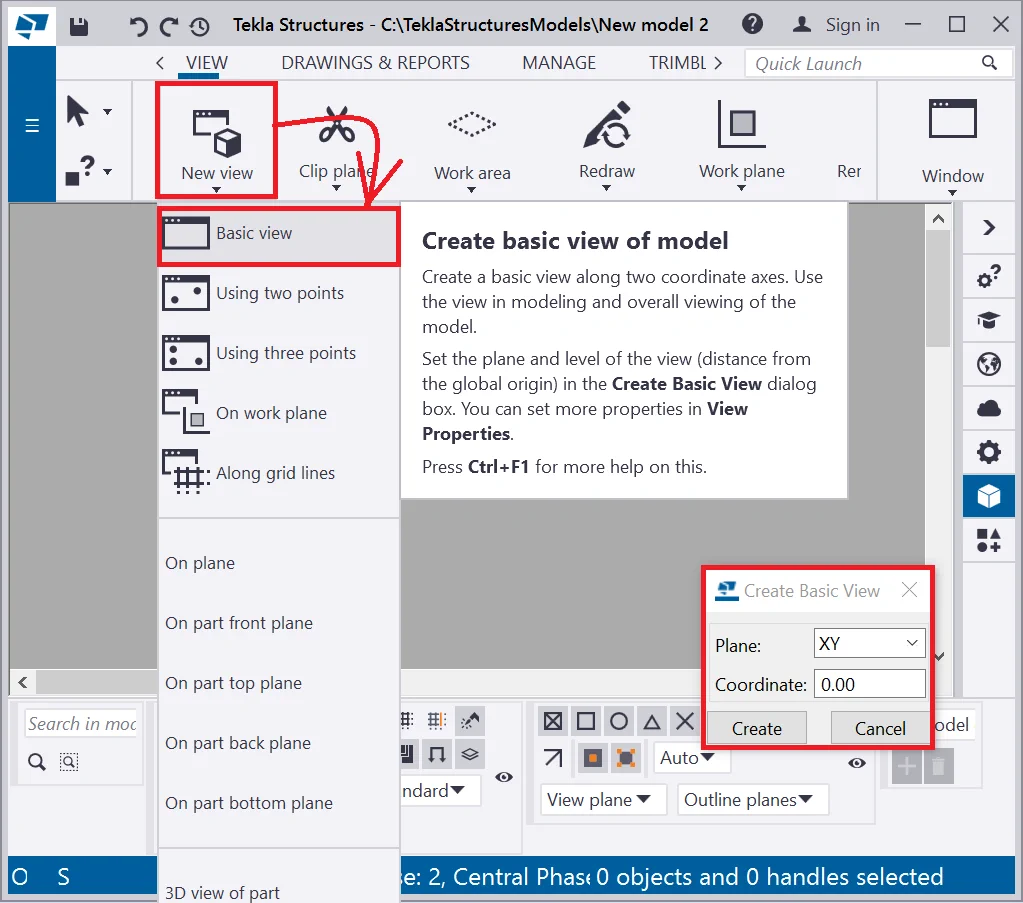
Create a view to see the model.
There are three options available when creating a basic view, which are: XY view, XZ view, ZY view. Create XY, XZ, ZY views. Refer to the below pictures:
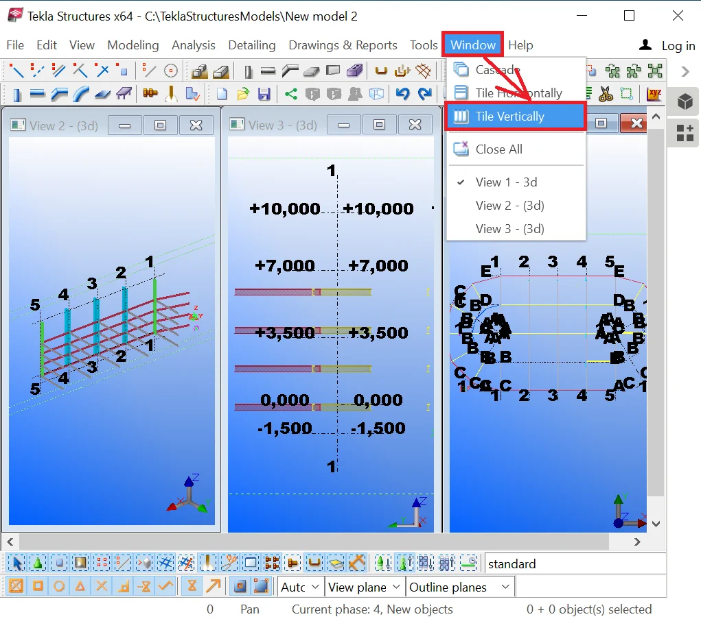
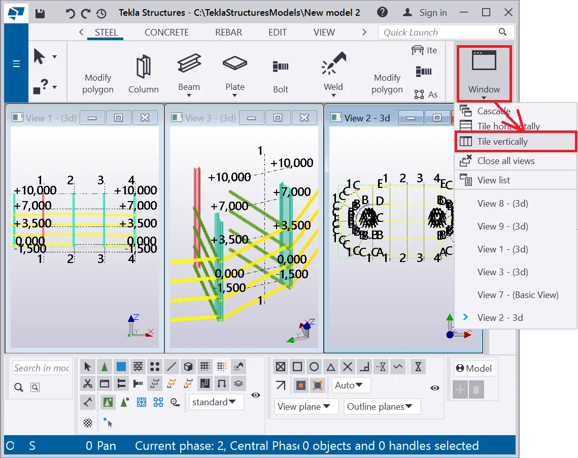
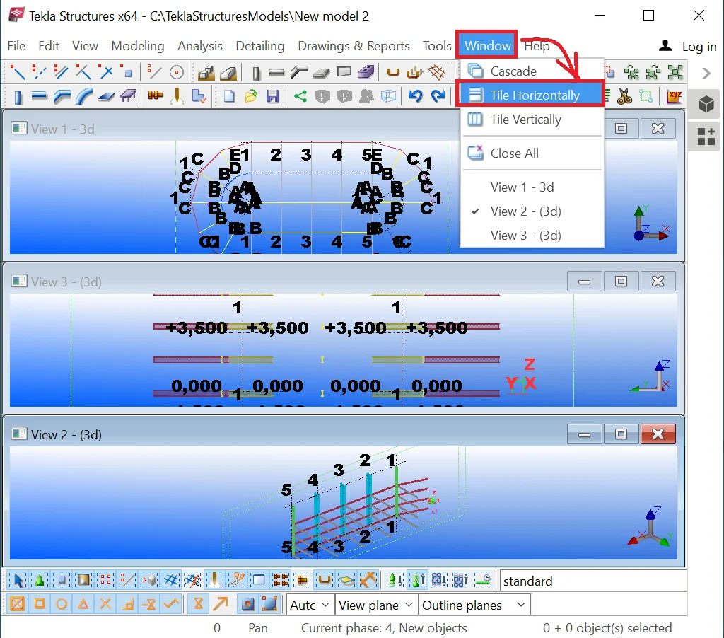
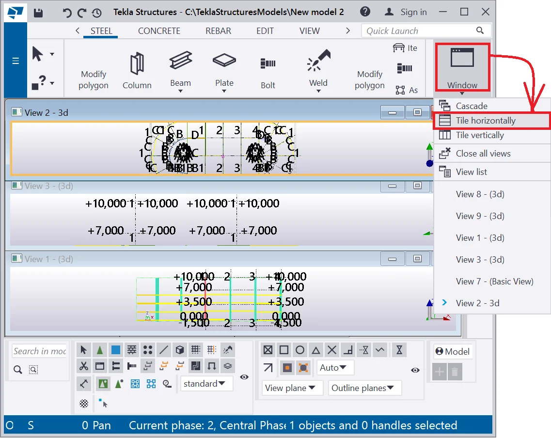
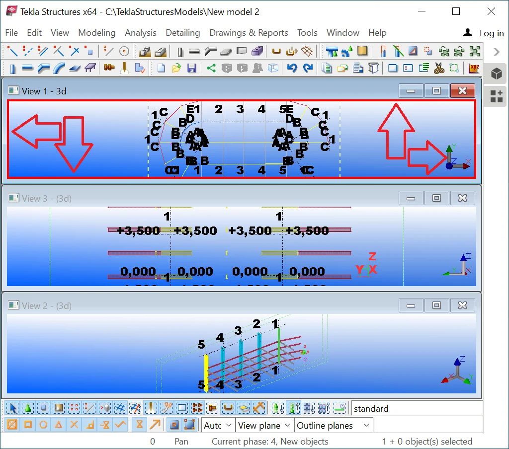
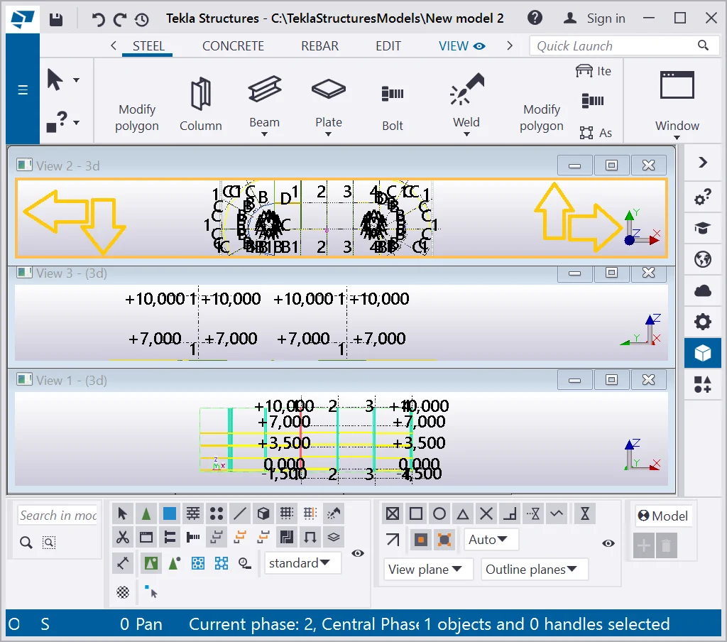
It is possible to arrange the views by tiling them vertically. Some parts
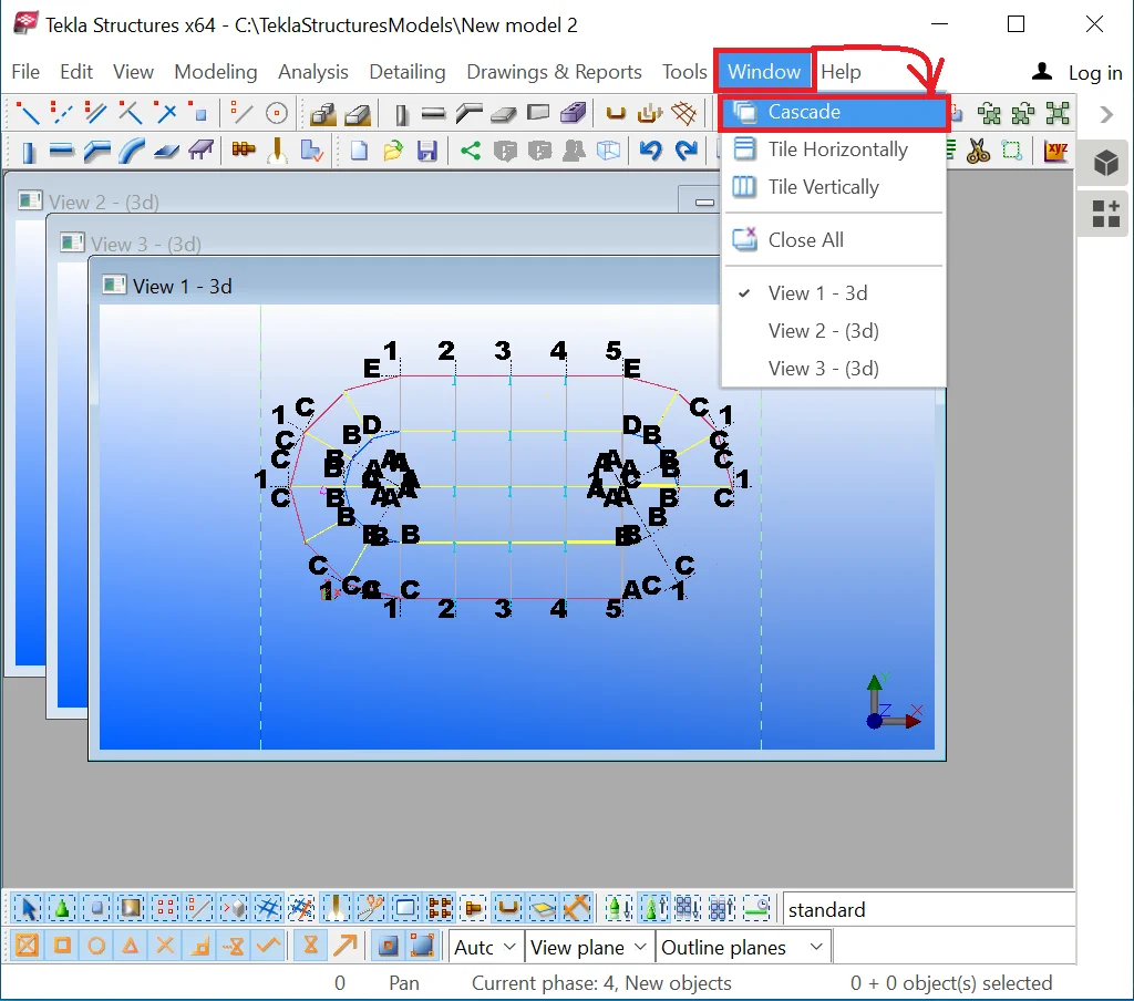
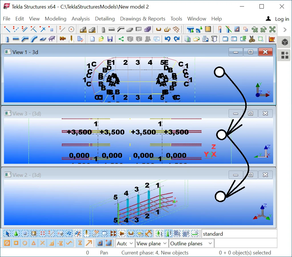
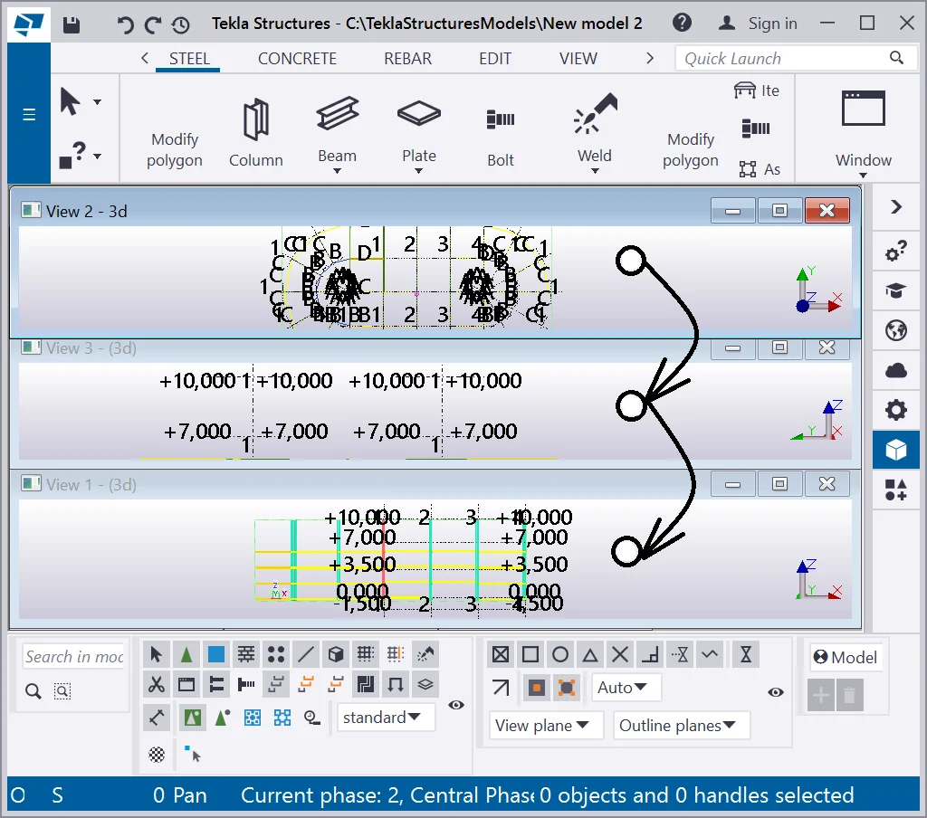
You can arrange the views in the cascade.

Tile the views horizontally.
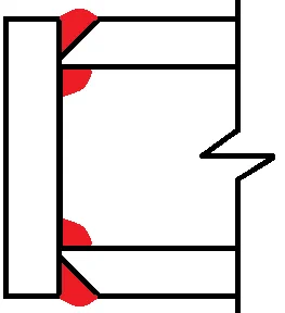
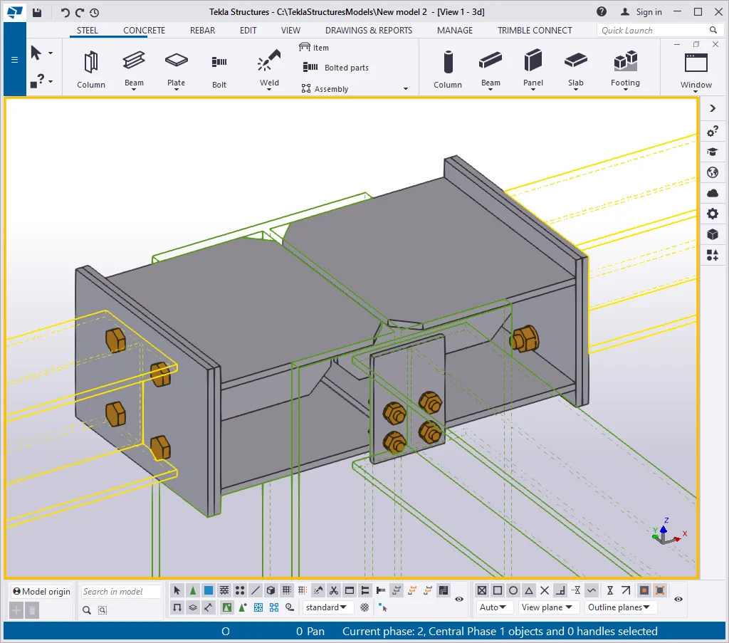
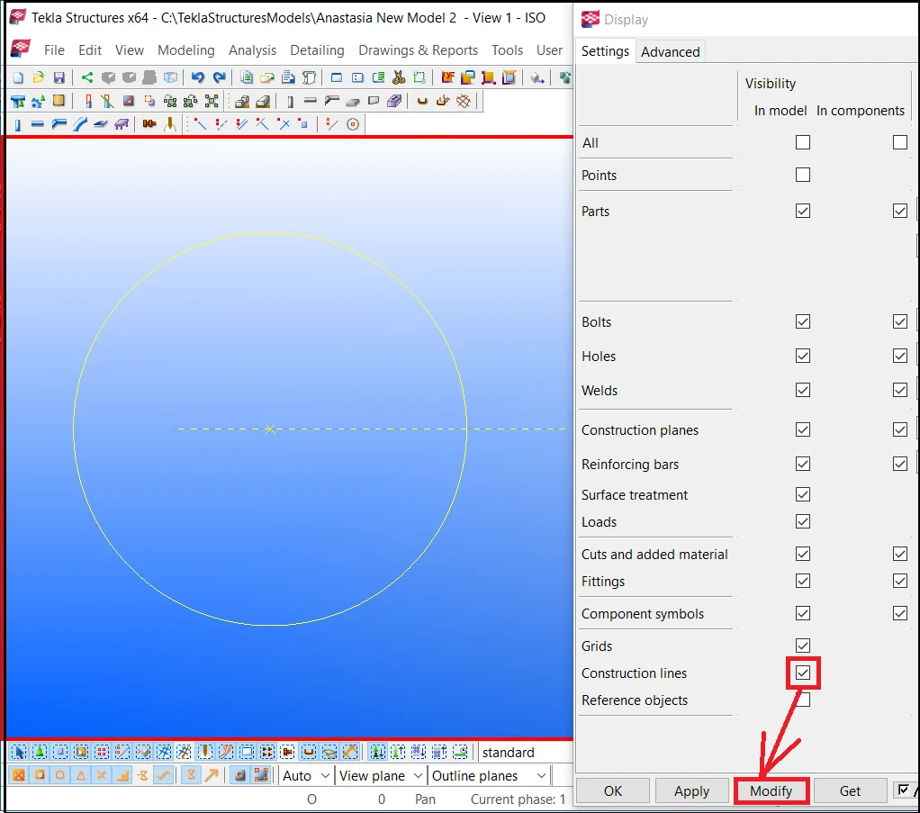
The "Display" button of the "View properties" window configures the rendering type of various objects. It is a very useful tool as some object types, such as welding, bolted joints, additional geometry, and others are not necessarily to be displayed. It is important to mention that configuring the rendering mode does not delete the objects, but just hides them off the view. Before getting to the "View properties" list, first of all, let's get acquainted with the “components” as the majority of settings are focused exactly on these.
Create several components and examine how the rendering settings work.
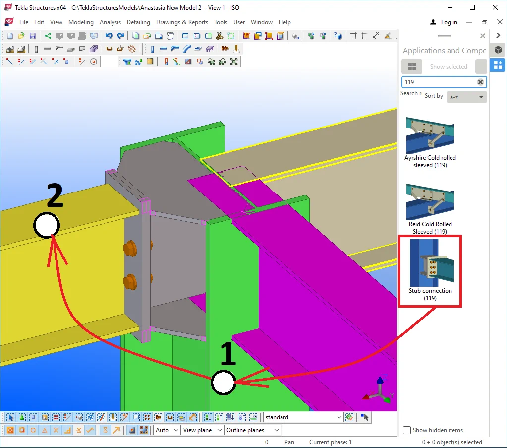
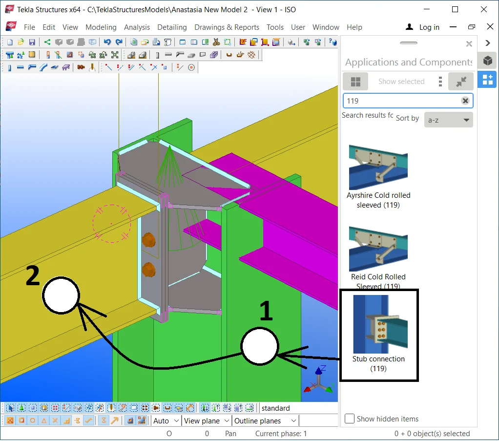
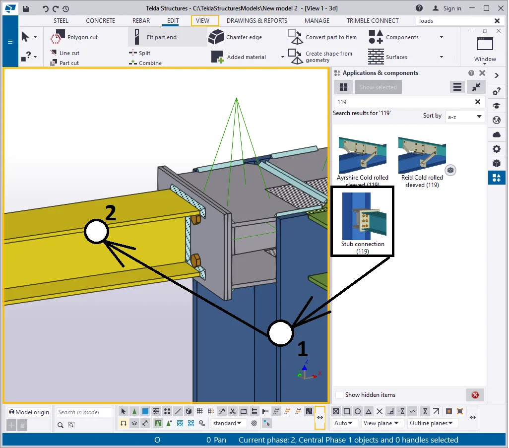
Go to the column located at the intersection of the grid lines А and 2. Enable the Ctrl+F hotkey combination to get to the "Applications and Components" catalog.
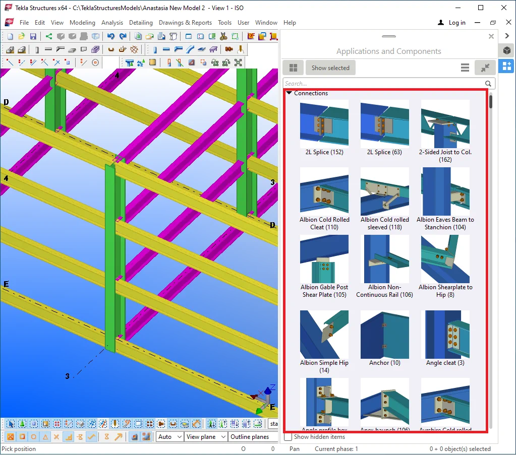

Write into the search bar number 119 - one of the component’s numbers.
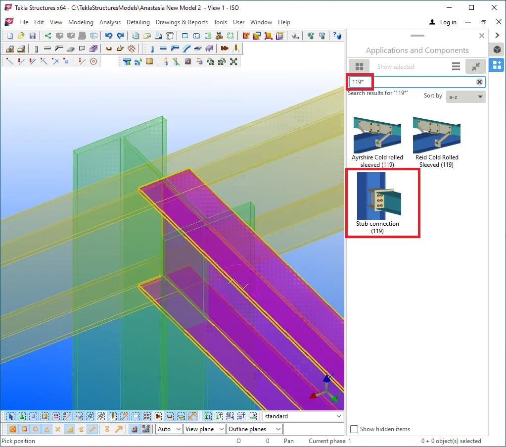
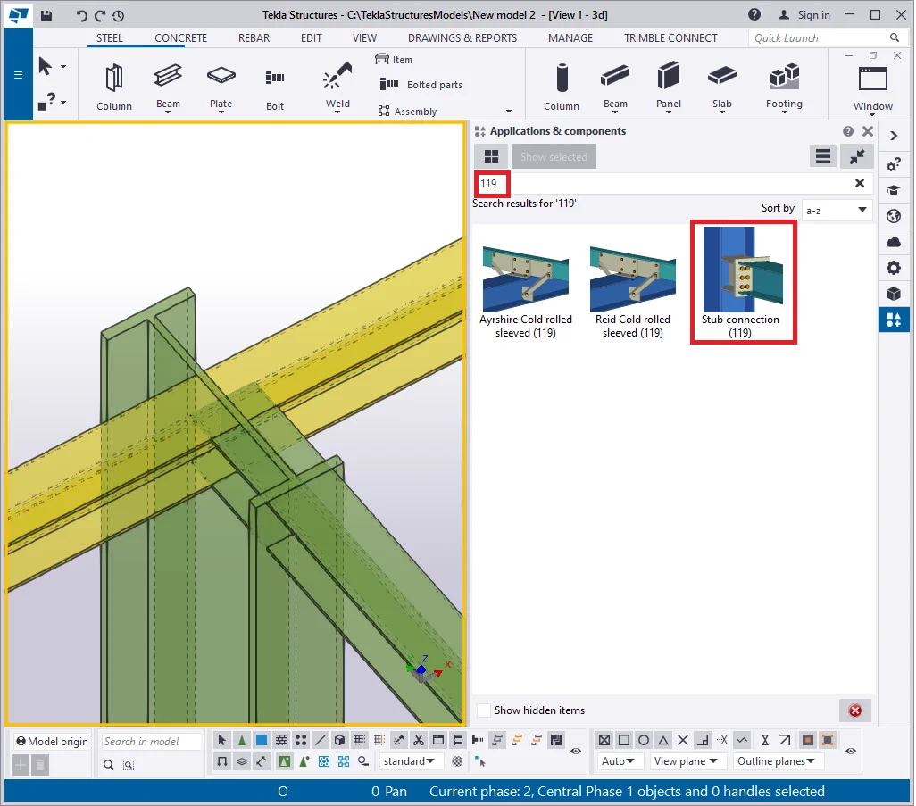
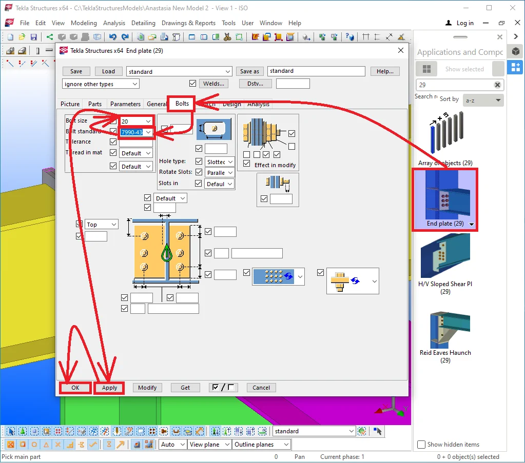
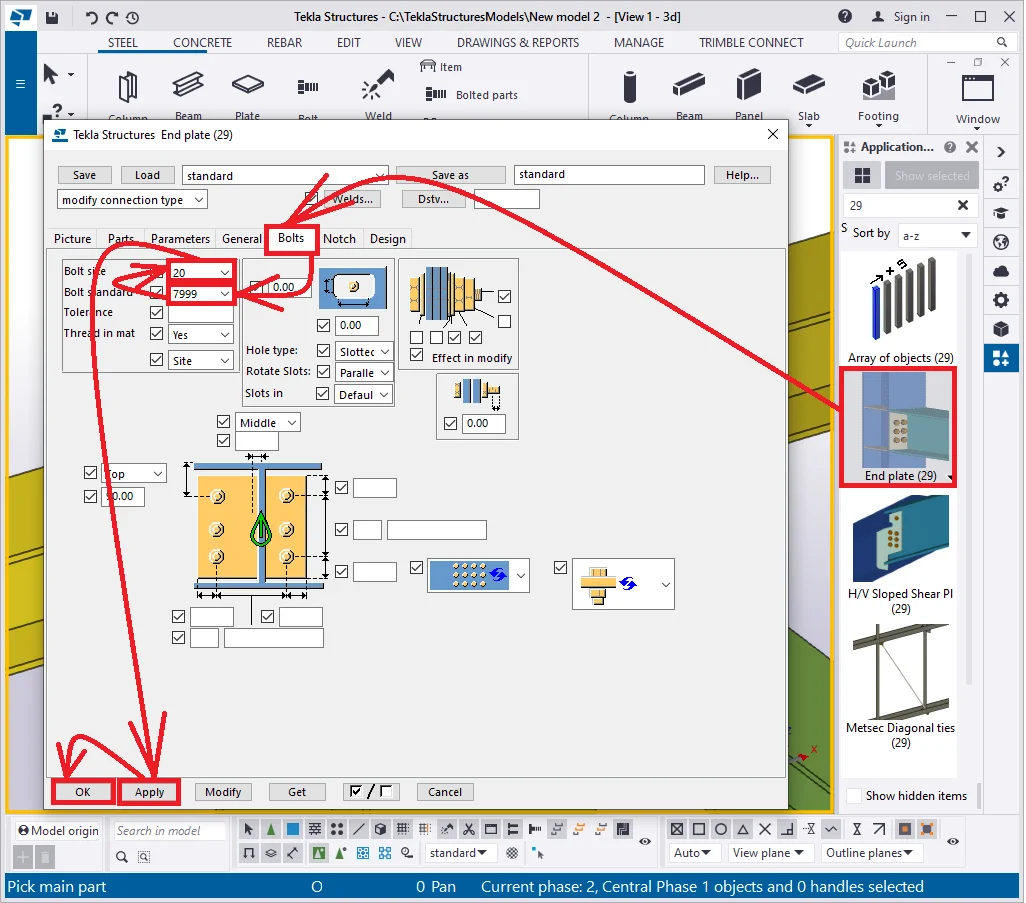
Insert this component in the model. But first of all, let's configure the bolts' standard and size parameters of the component by double-clicking on the component icon.
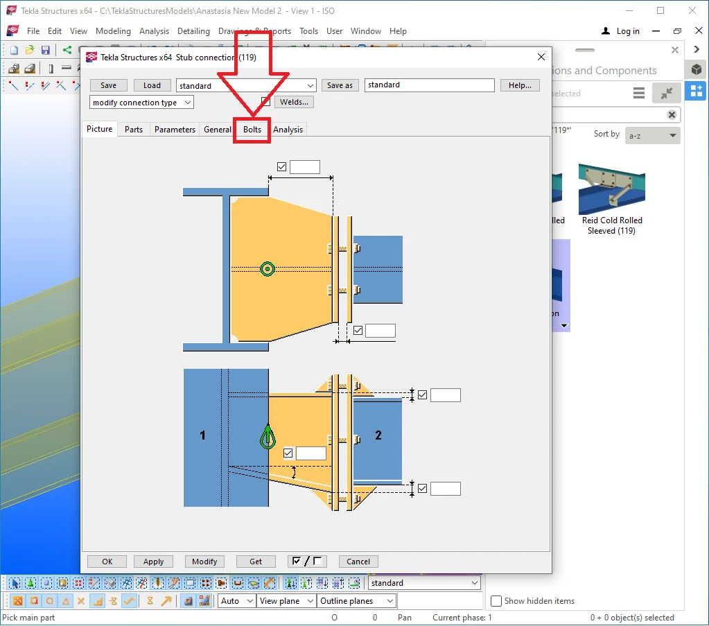
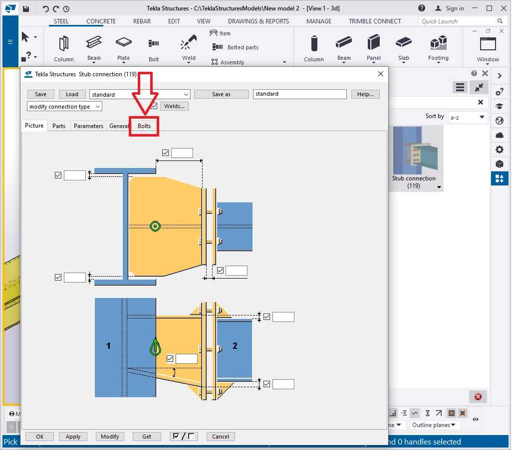
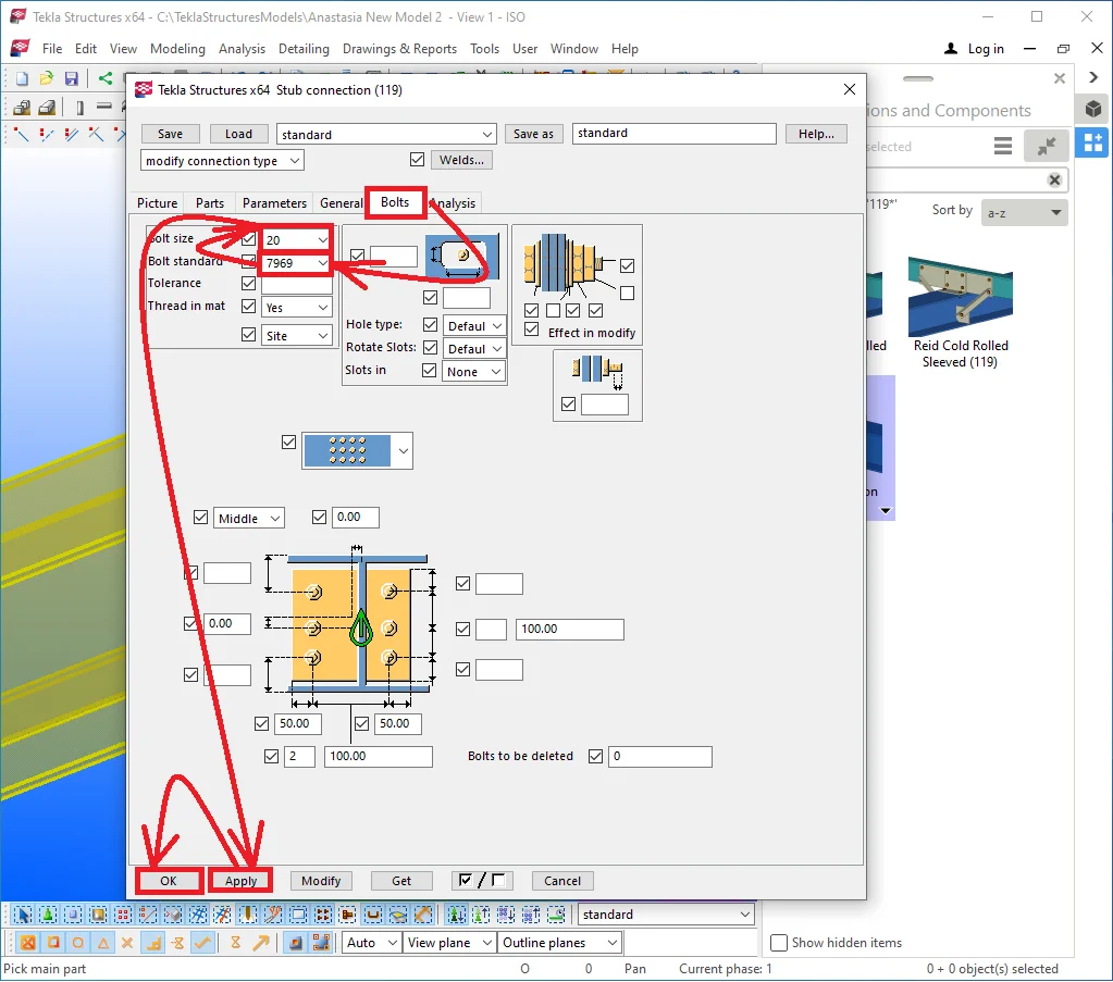
At the window opened go to the “Bolts” tab and proceed as
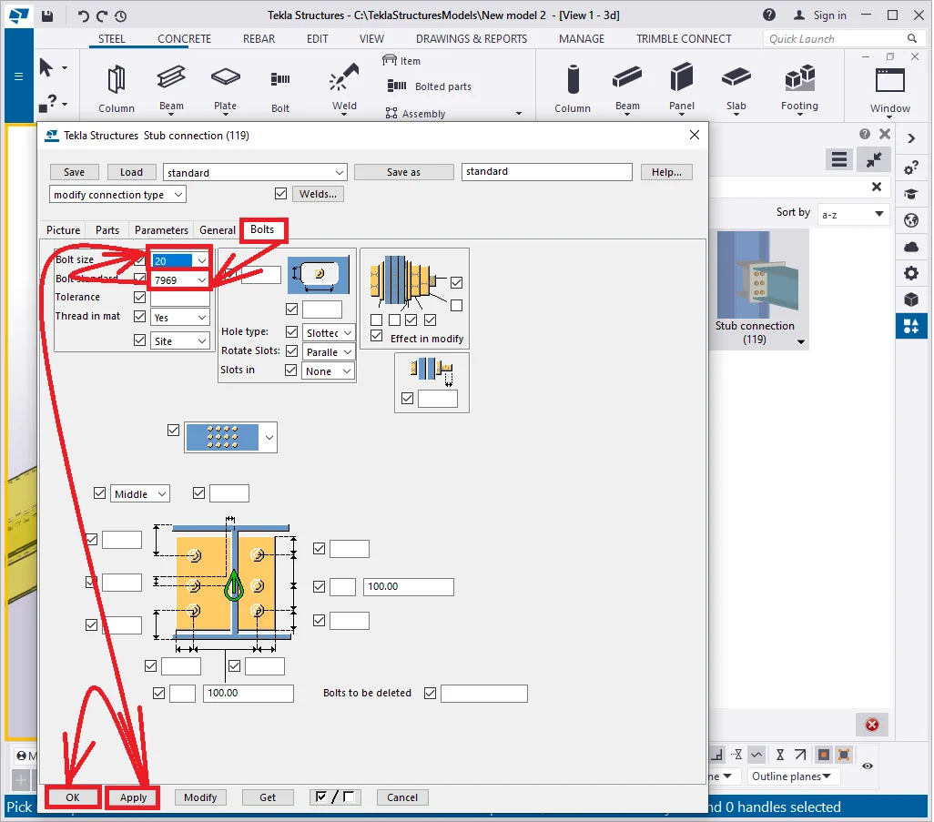
The algorithm for creating a component is as follows:
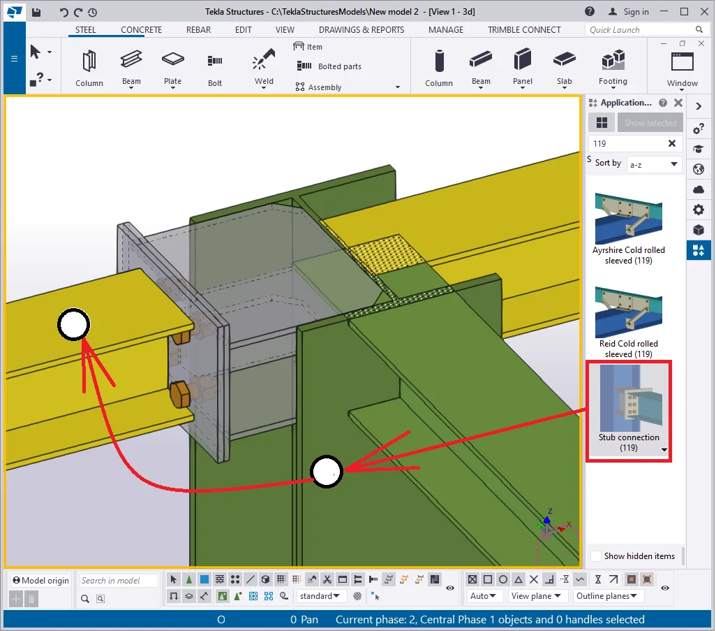
Proceed in a similar way for the second beam.

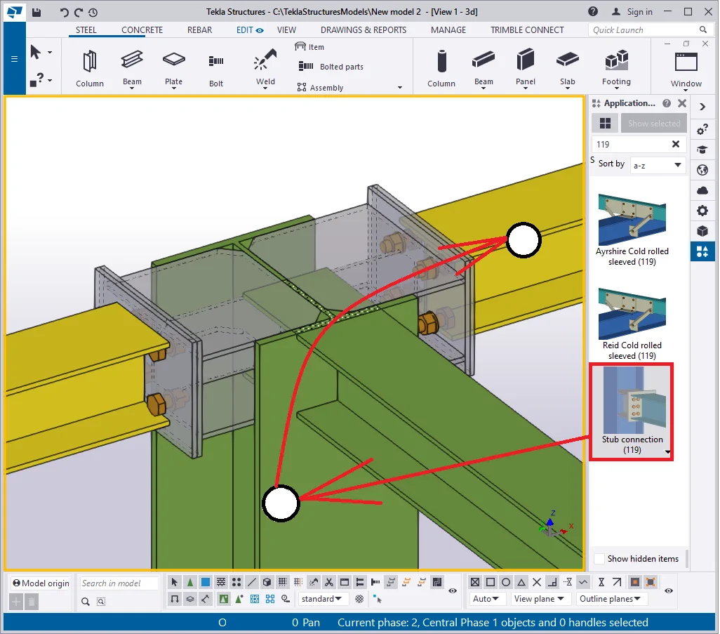
Let’s create one more component joining the 3rd beam to the column's
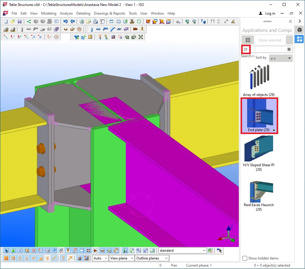
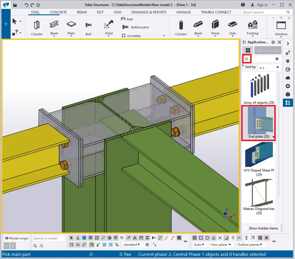
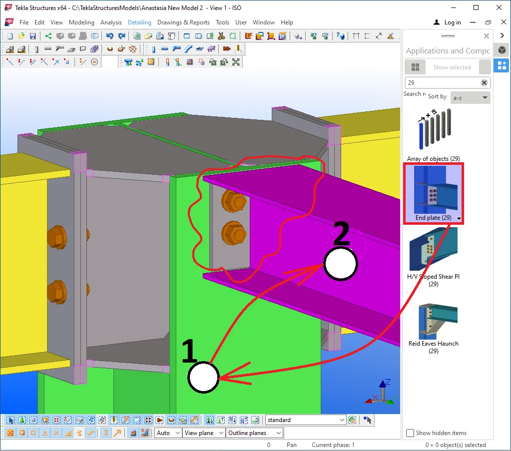
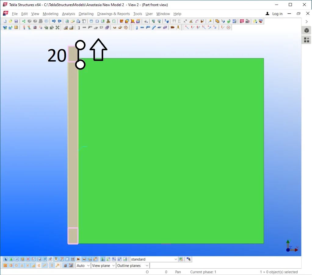
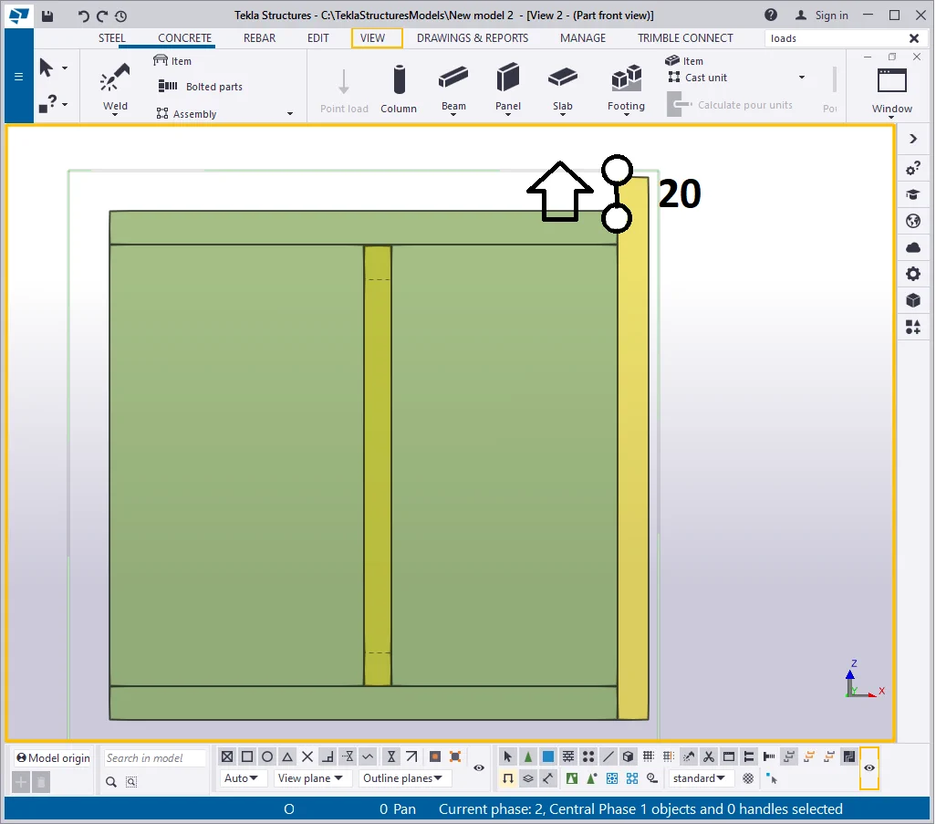
Find at the Applications and components catalogue the component No 29 and preset it by configuring the bolt’s standard and size parameters. Set up the bolt’s size at 20 mm. Refer to the picture below:
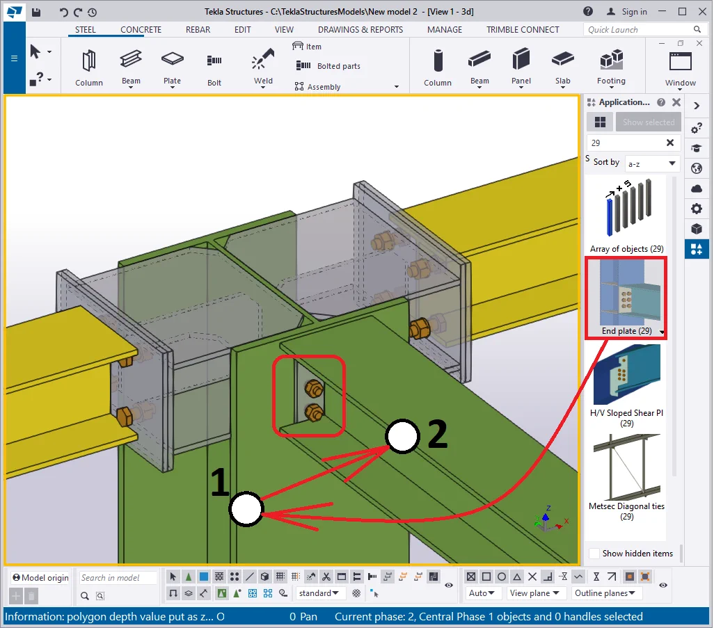
Now create the component between the column’s flange and the 3rd
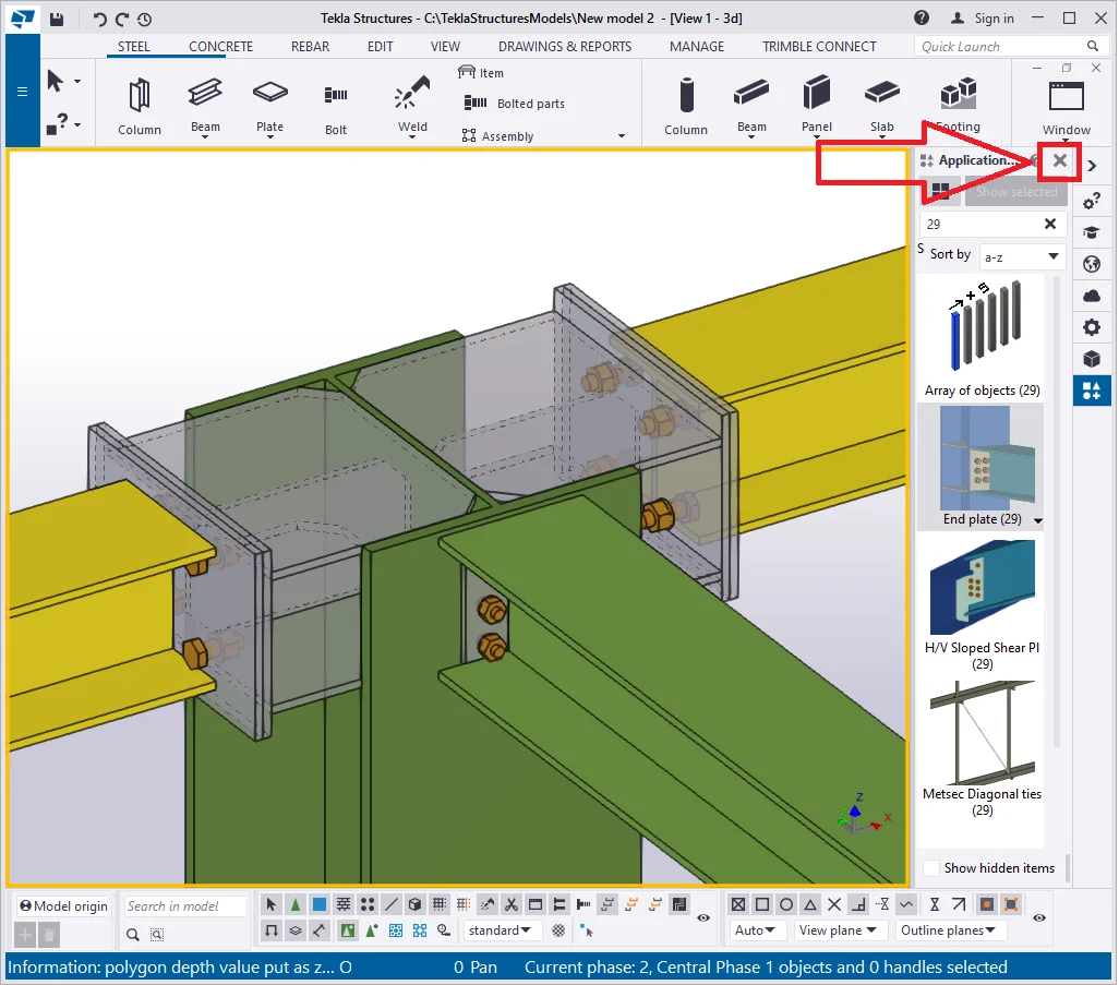
Close the “Applications and component” catalogue.

Now we have created a new object type - the component.
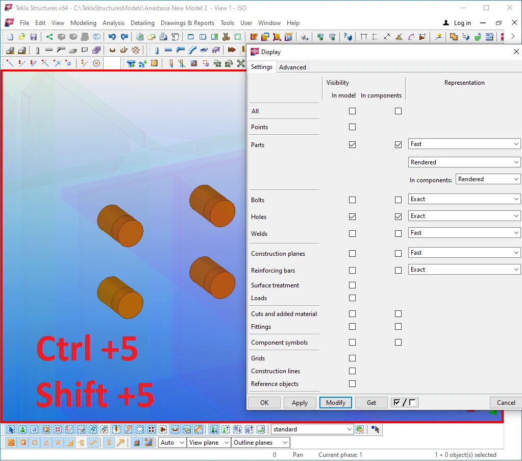
Try out toggling between display color modes by using the hotkey combinations
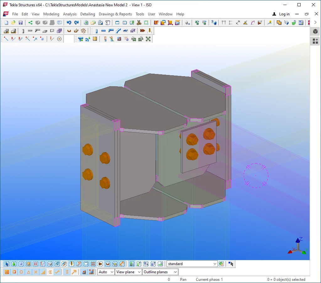
As you can see, switching the display color mode does not affect the component's rendering, this being the TS instrumentation allowing it to easily look over the joints without hiding the other objects. Changing a component’s display color mode is done by toggling between the following hotkey combinations: Shift+1, Shift+2, Shift+3, Shift+4, Shift+5. Try using them on your own.
By a double-click at any point of the work area open the “View
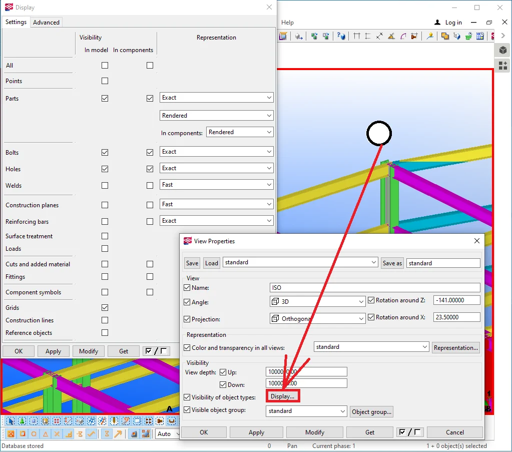
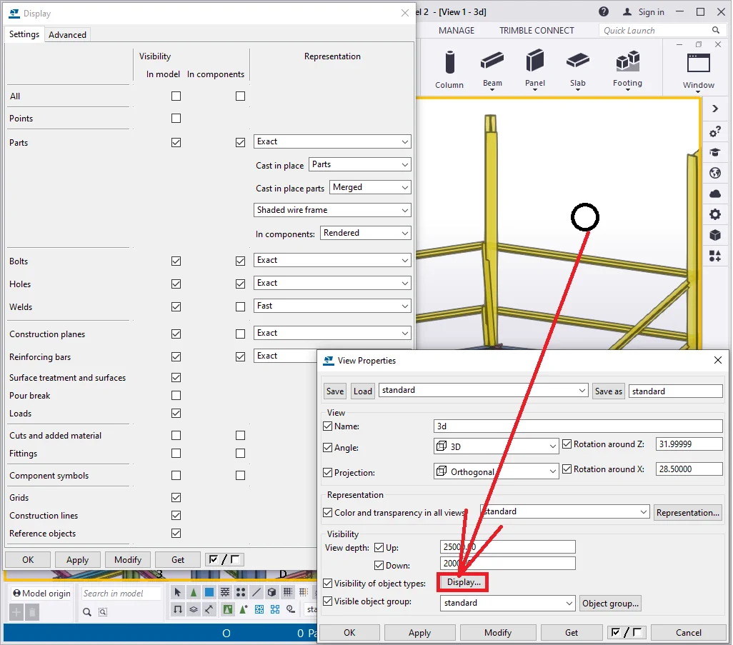
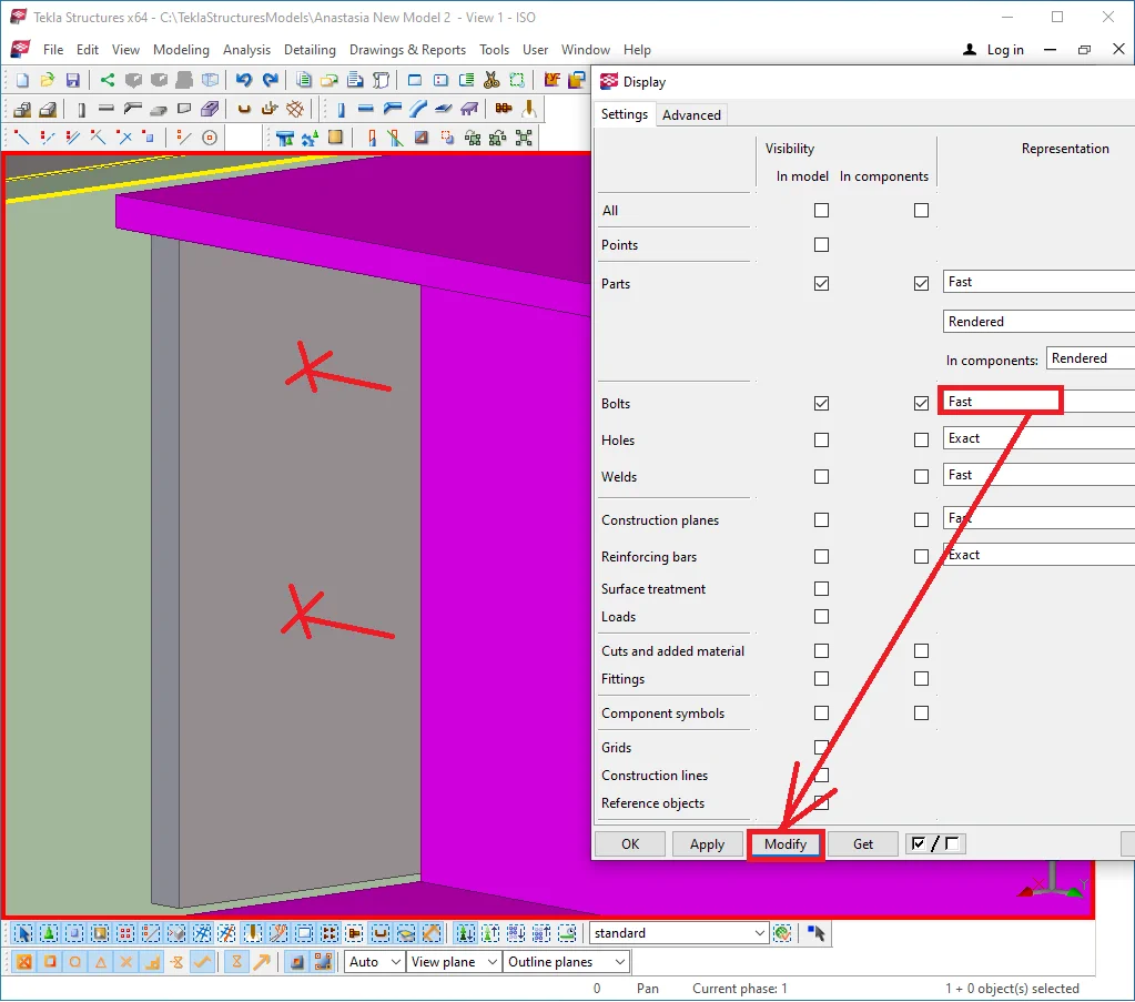
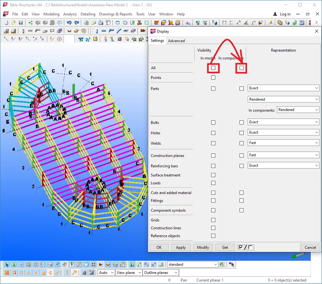
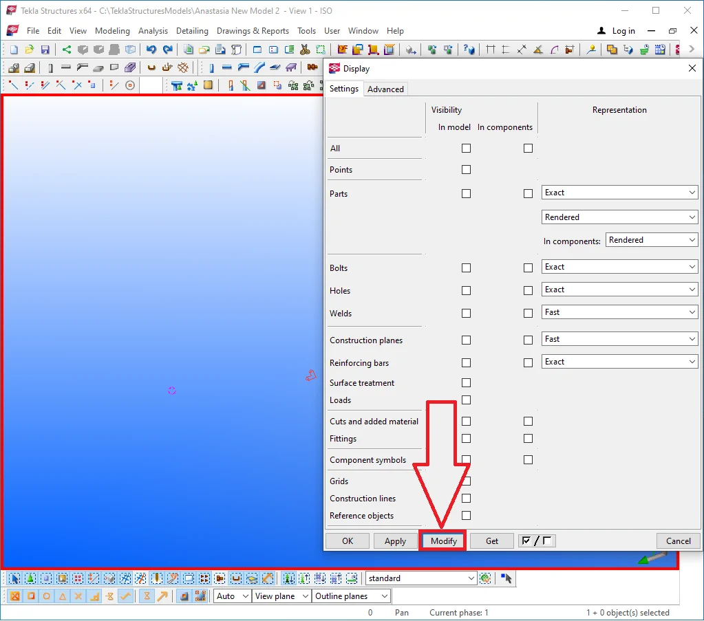
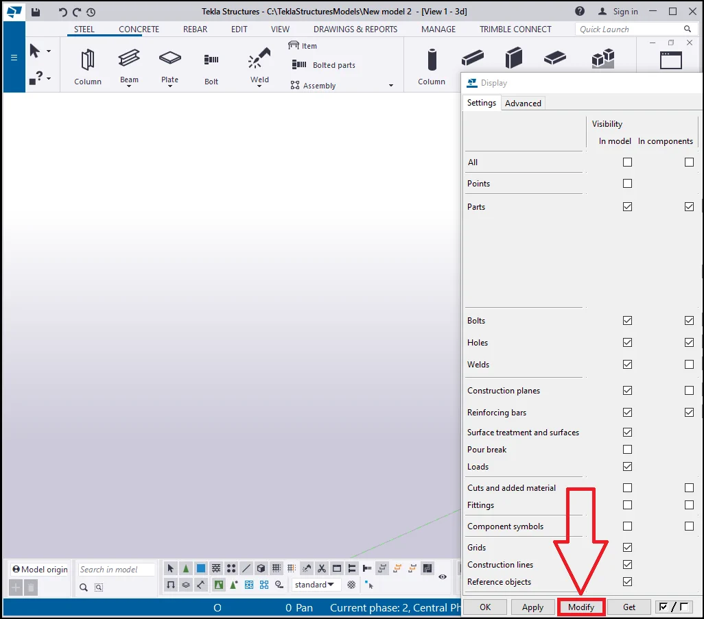
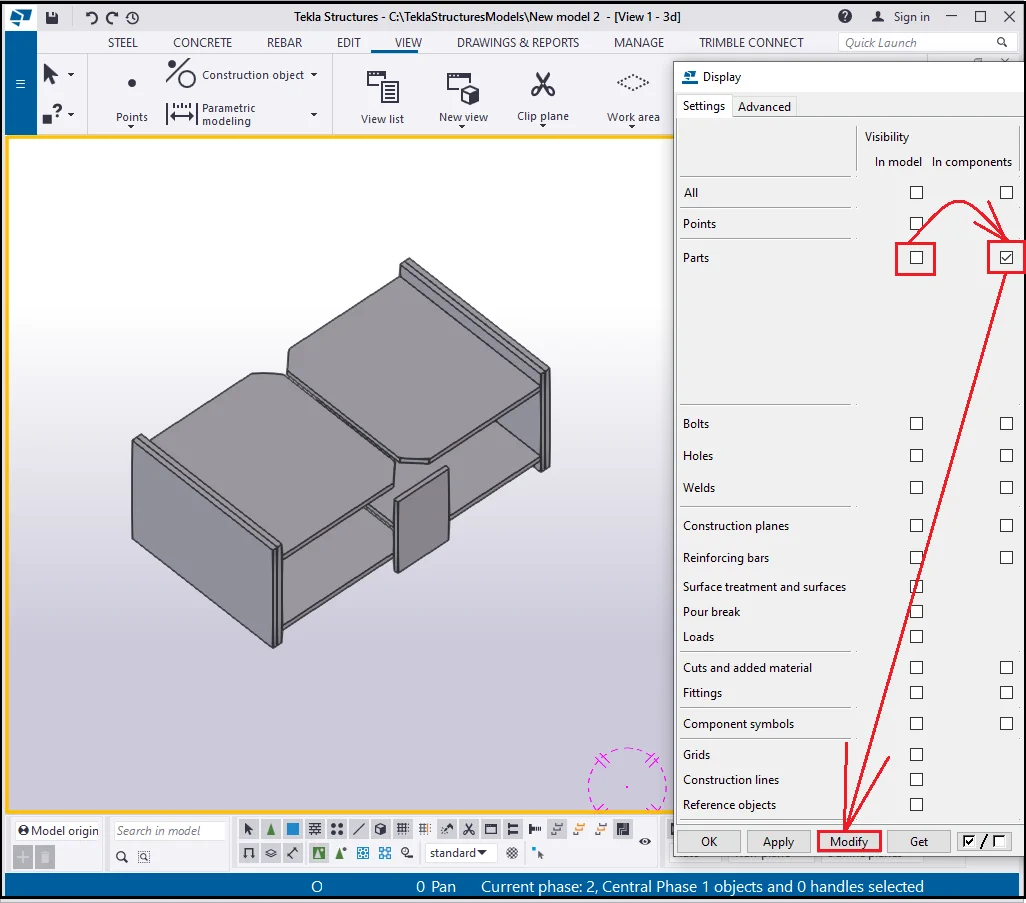
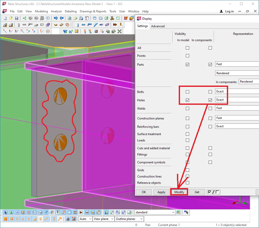
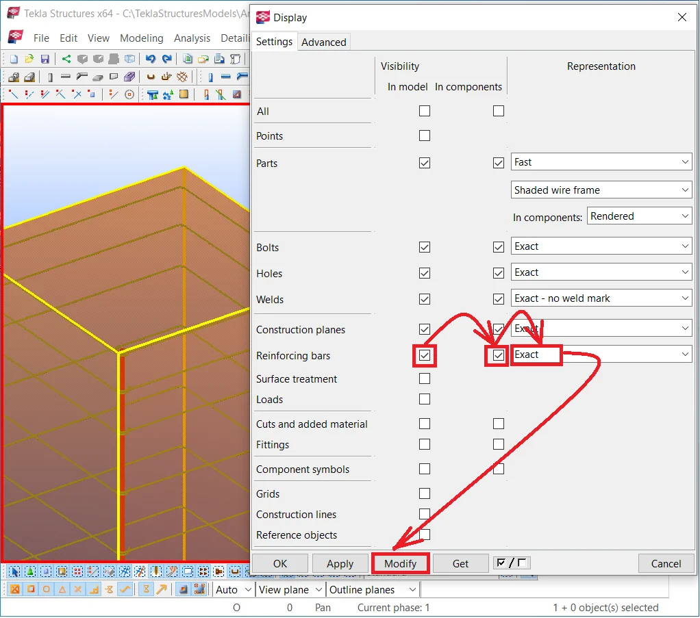
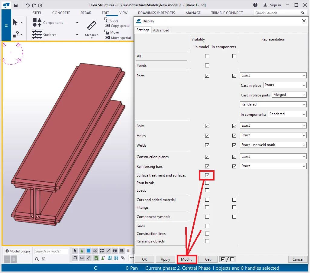
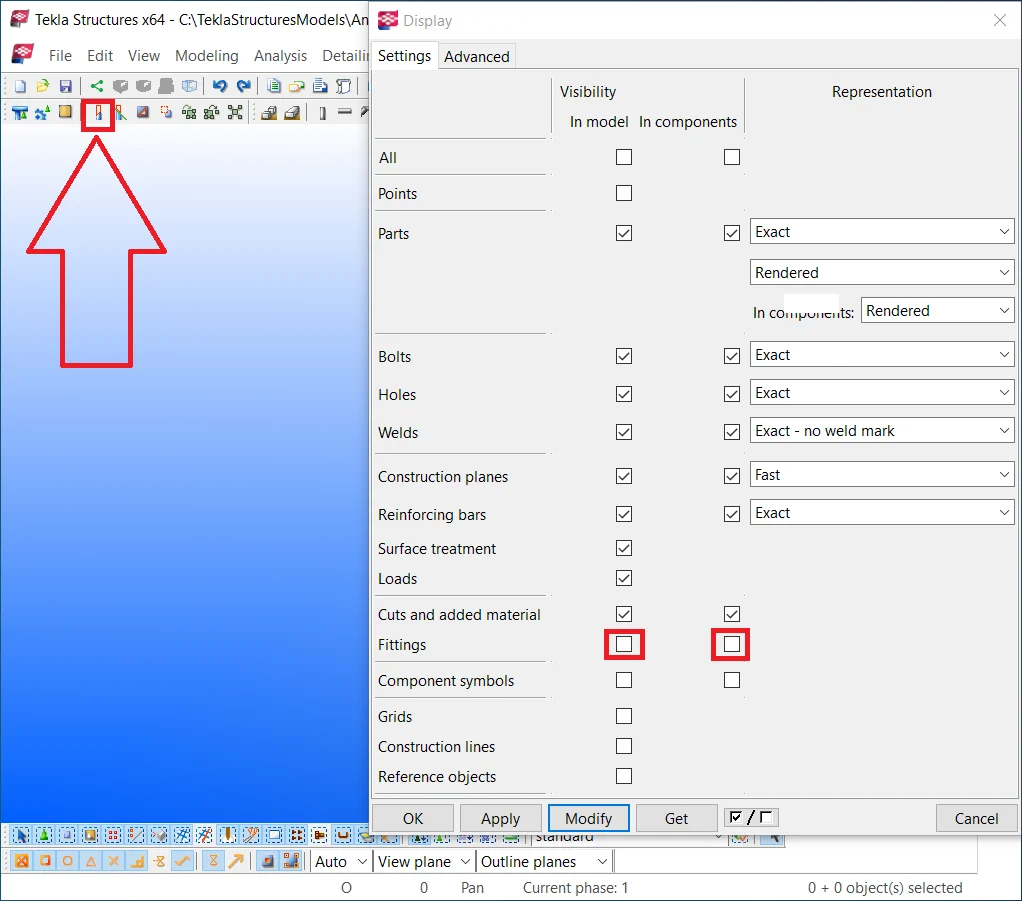
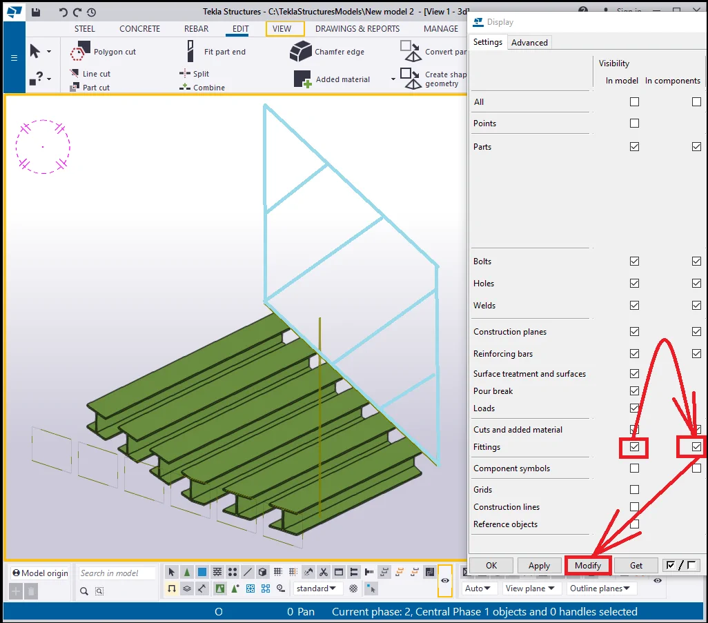
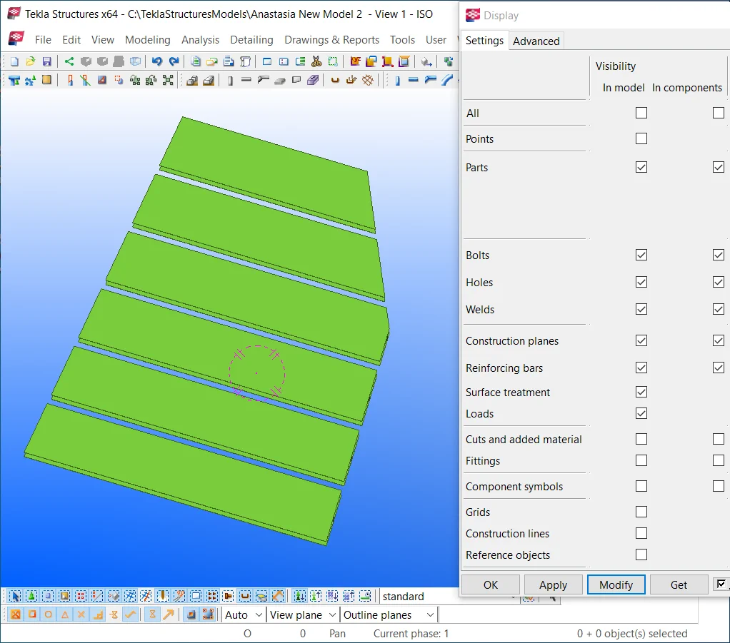
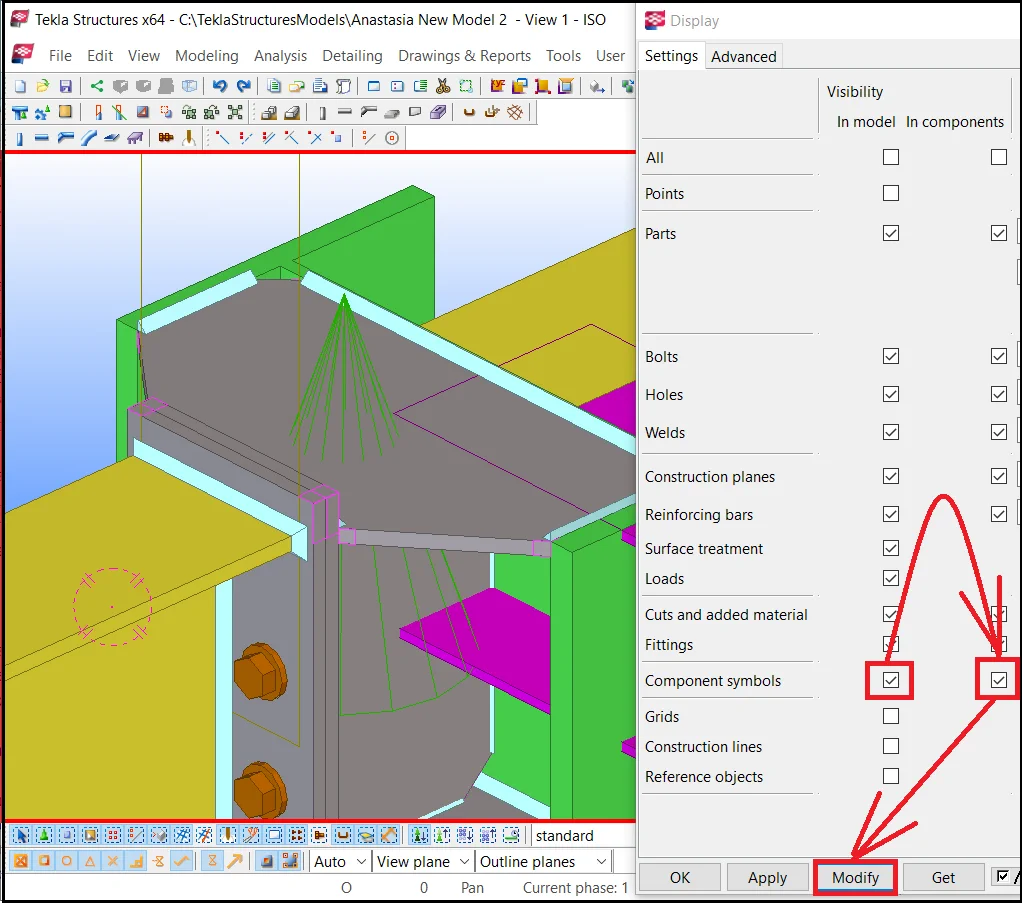
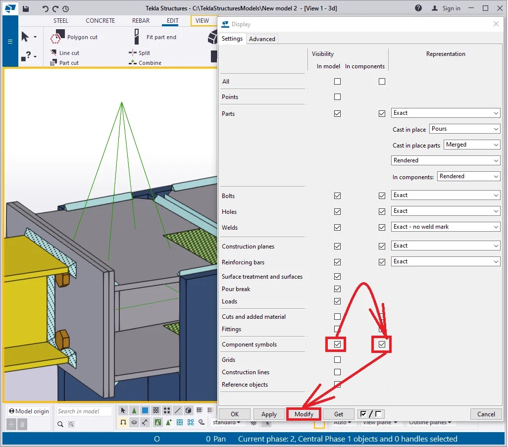
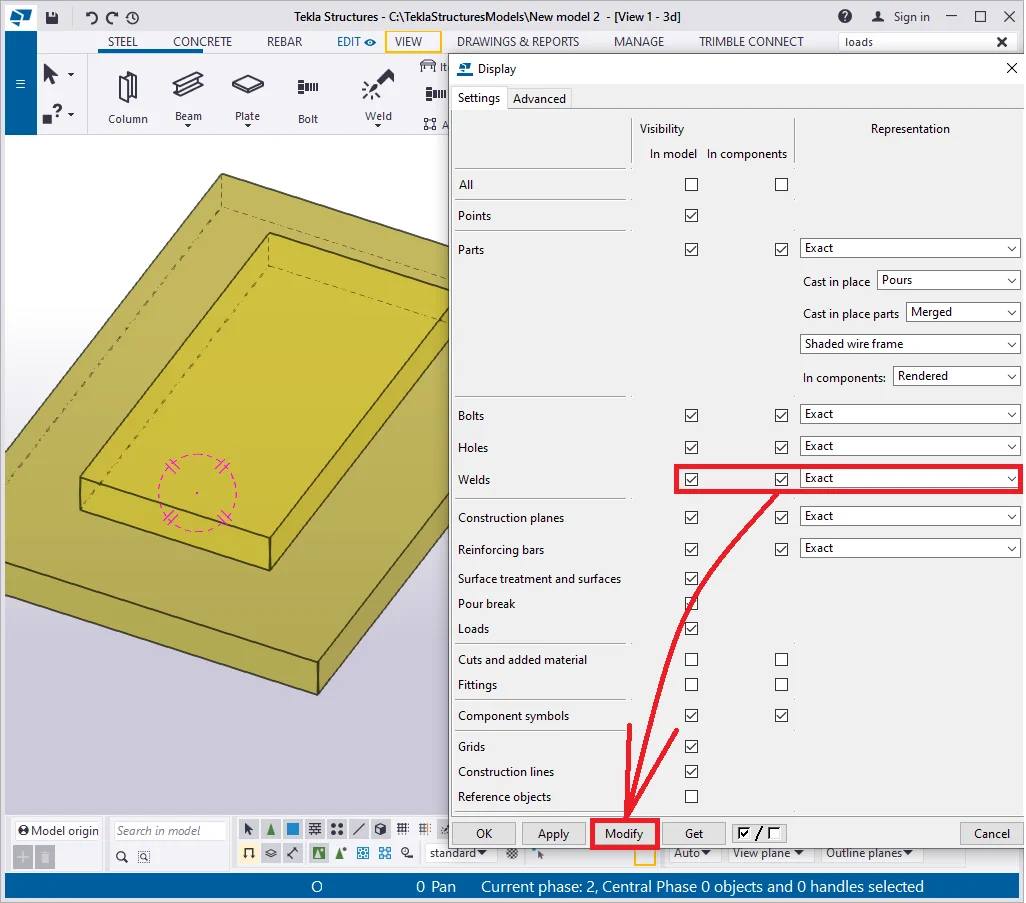
The “Display” menu consists of numerous rows and columns, forming a table. In the below picture you can see each row numbered and each column color-coded. Let’s review these on a case-by-case basis.

Columns: Visibility in model/ Visibility in components sections
The column framed with red refers to the simple objects without adjoint components. The one framed in green refers to the objects, joined to each other by a component.
Item 1 -The "All" row - this row is a checkbox, which is simultaneously activating/ deactivating all the items. Deactivate all the checkboxes.

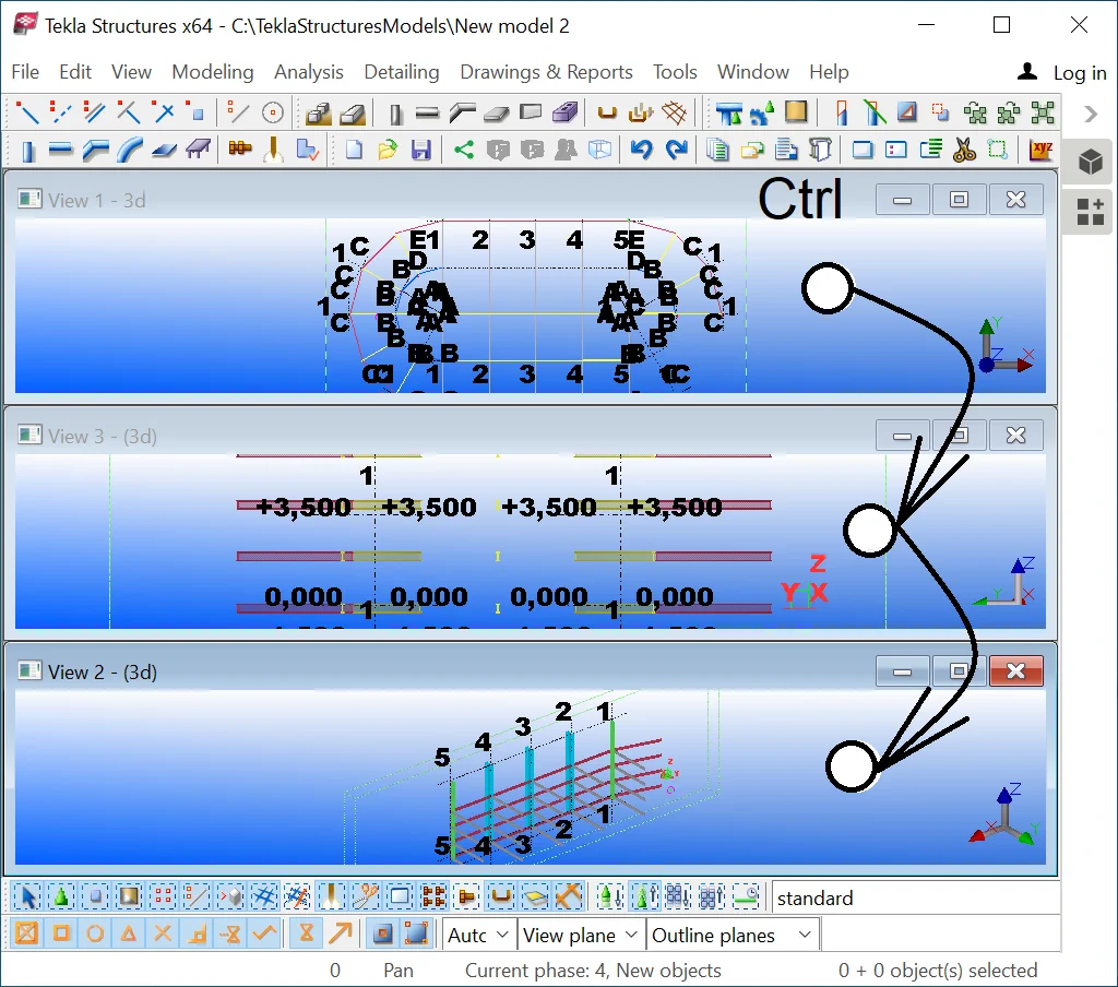
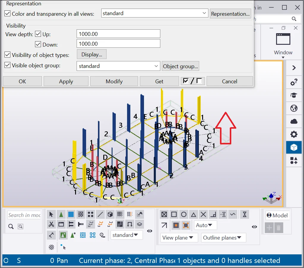
It is important to mention if none of the views is selected and if the “Modify” button is not pressed, then there will be no changes in the representation of the model. Thus, select the required view by a left-click on it. A selected view has a red/yellow frame on its circumference. To unselect a view, hold on to the Ctrl key pressed and make a left-click at any place of the view. Simultaneously selecting several views, applies the display settings configurations to all of them.
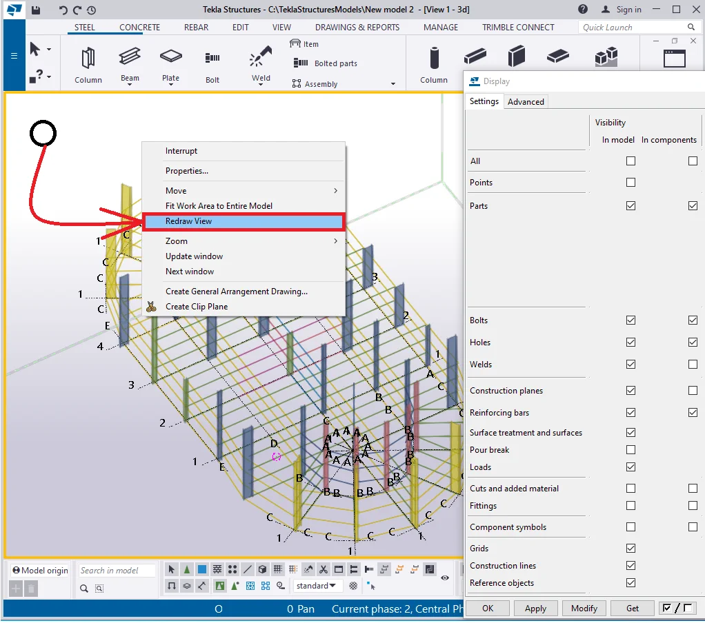
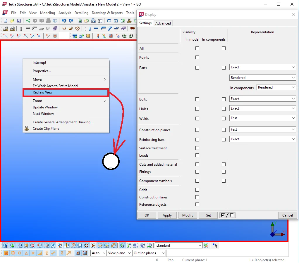
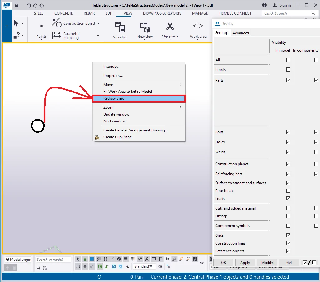
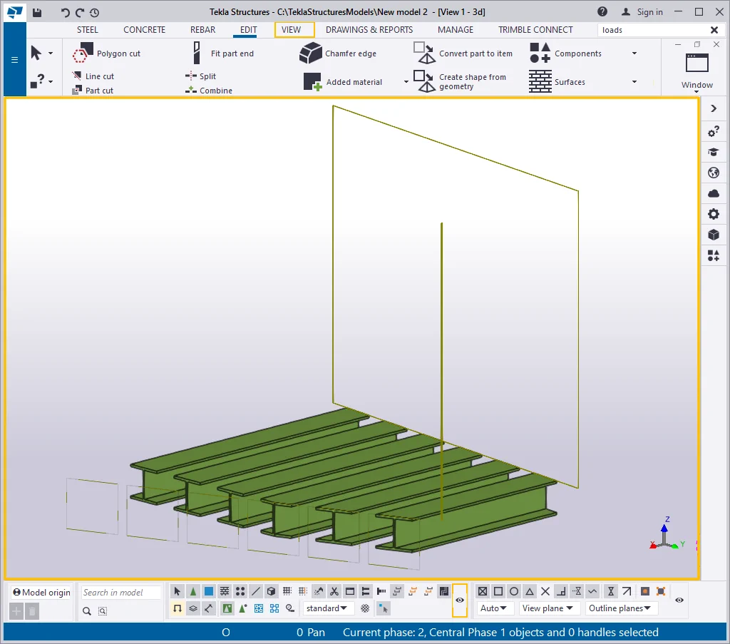
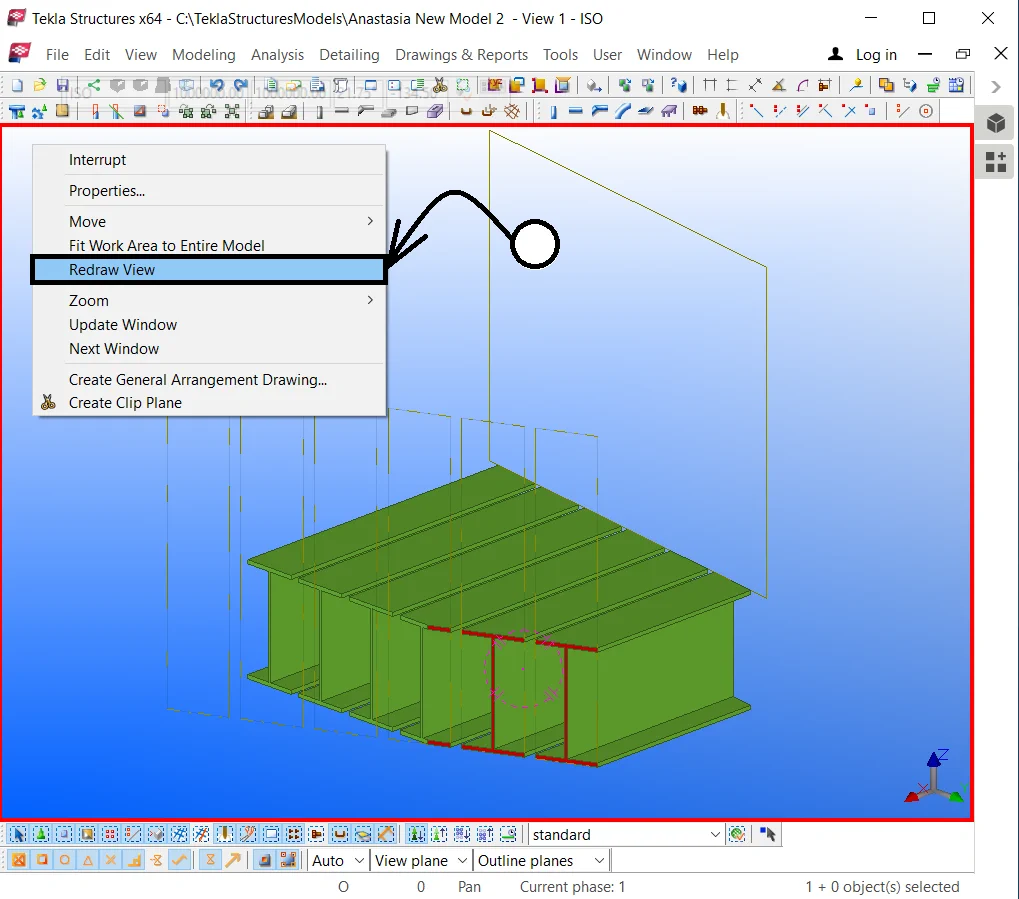
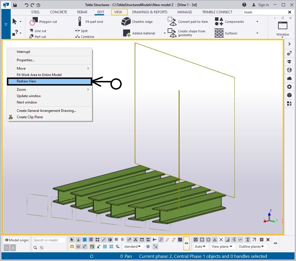
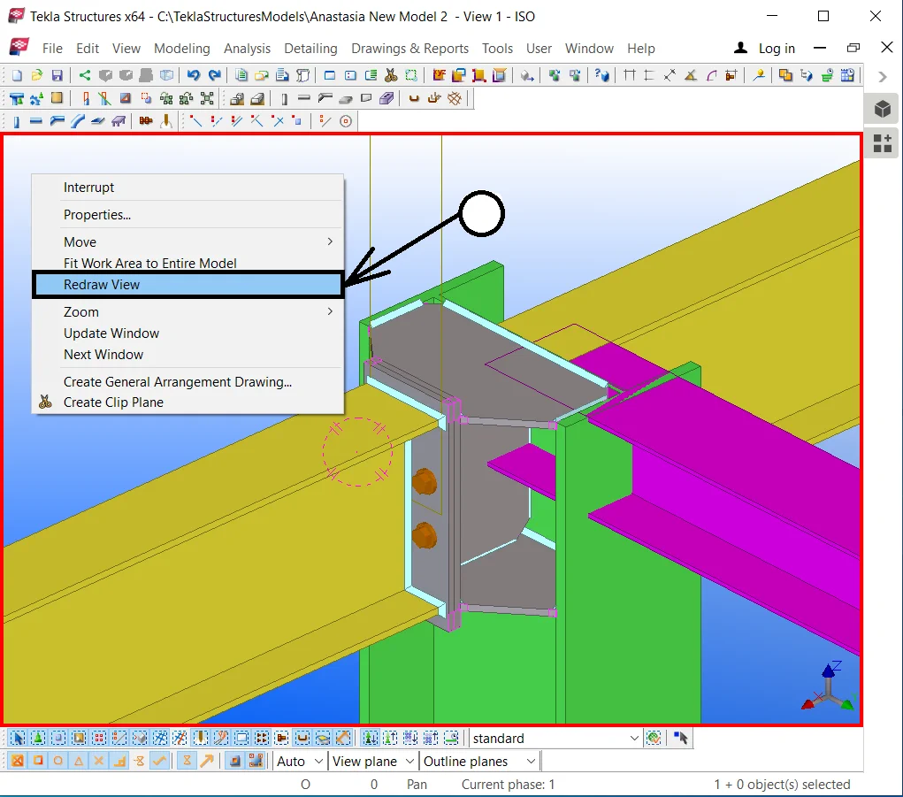
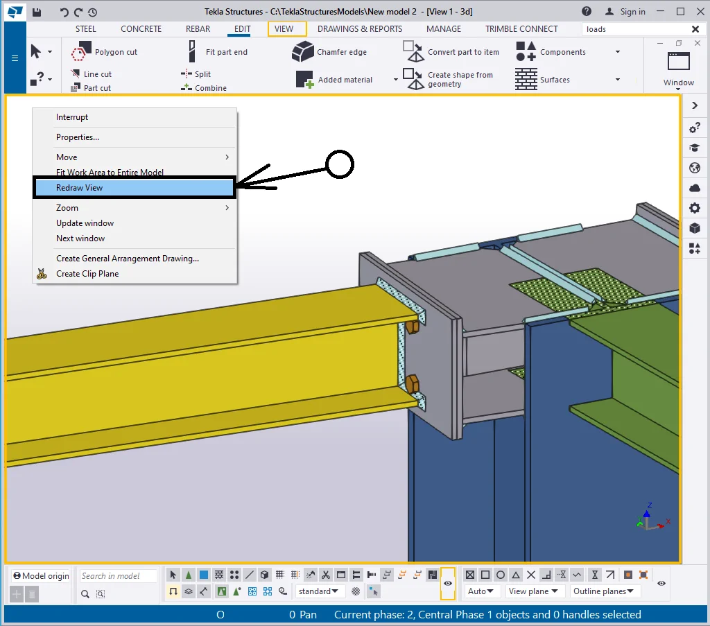
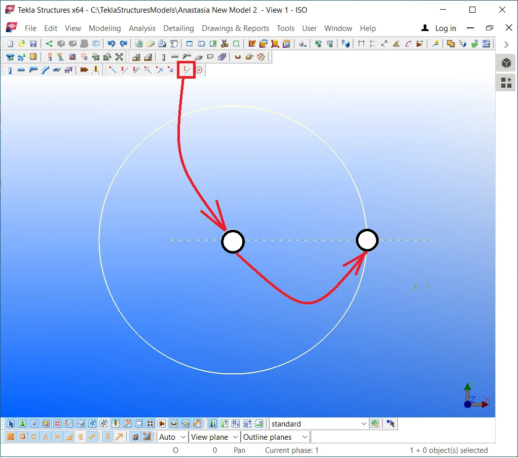
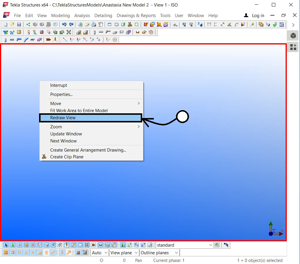
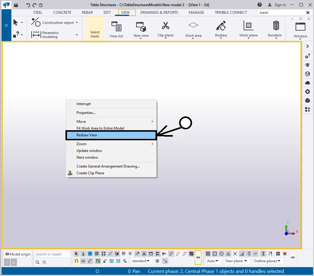
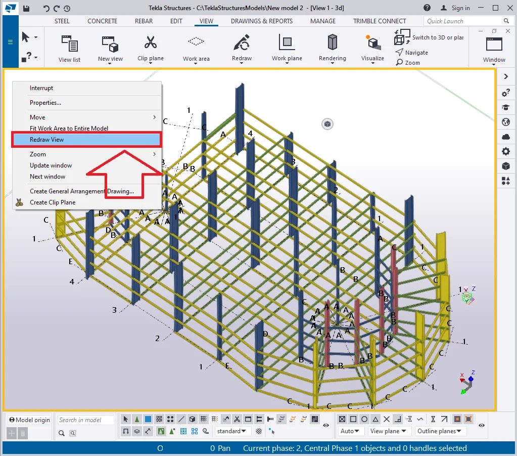
If after the properties are reconfigured there are several objects displayed at the view then go to the right-click menu and select the “Redraw view” tab. Thus the TS will automatically update the view properties according to the new settings specified.

Hence, according to the “Display” menu configurations, there
Item 2 - The " Points" raw - allows displaying construction geometry objects, such as points.
Let’s create several points with the “Points” checkbox
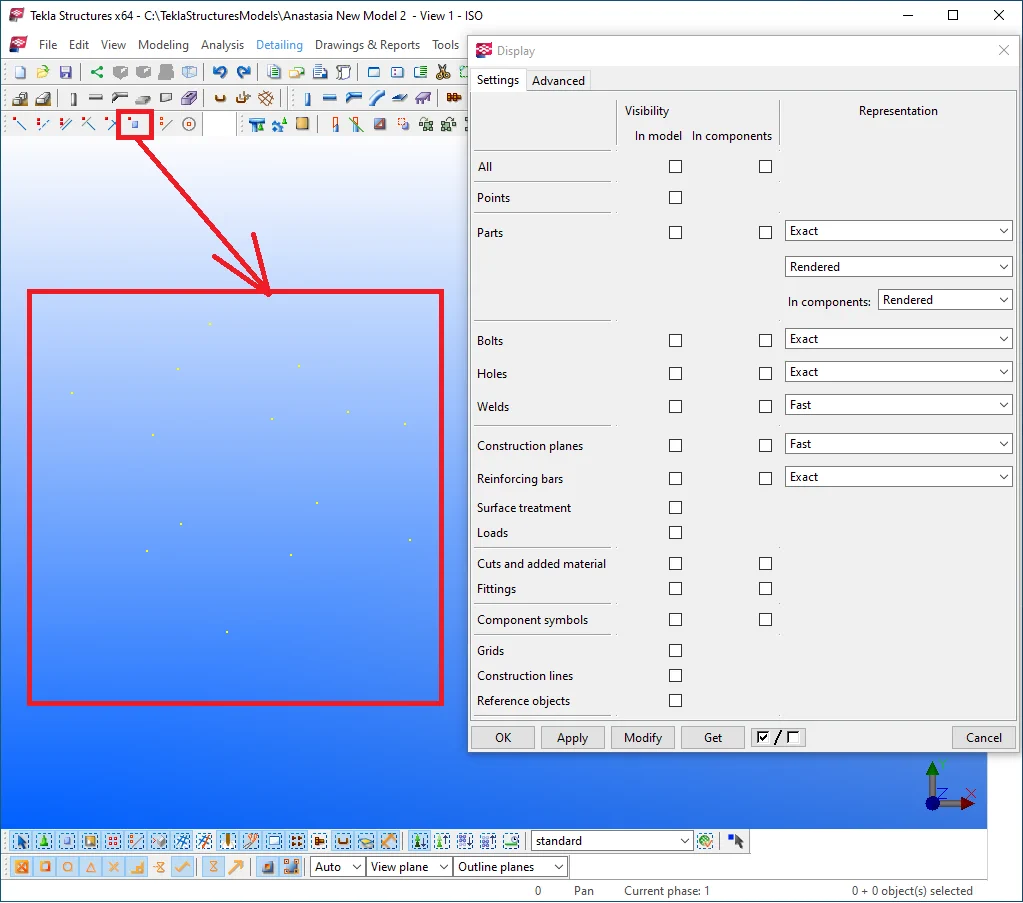
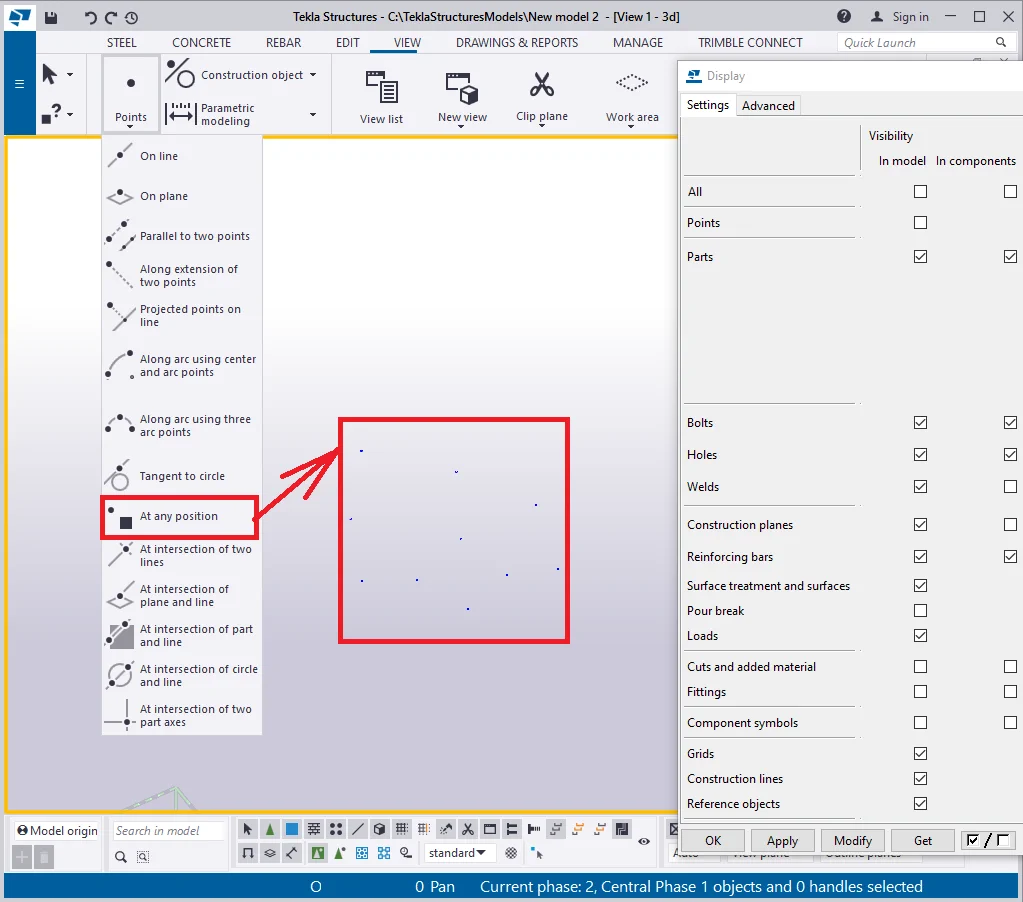
Thus we can create points, but they will not get displayed in the view.
Redrawing the view hides the points.
Now, let’s activate the “Points” check box and press
Note that there is no respective checkbox at the “Components”
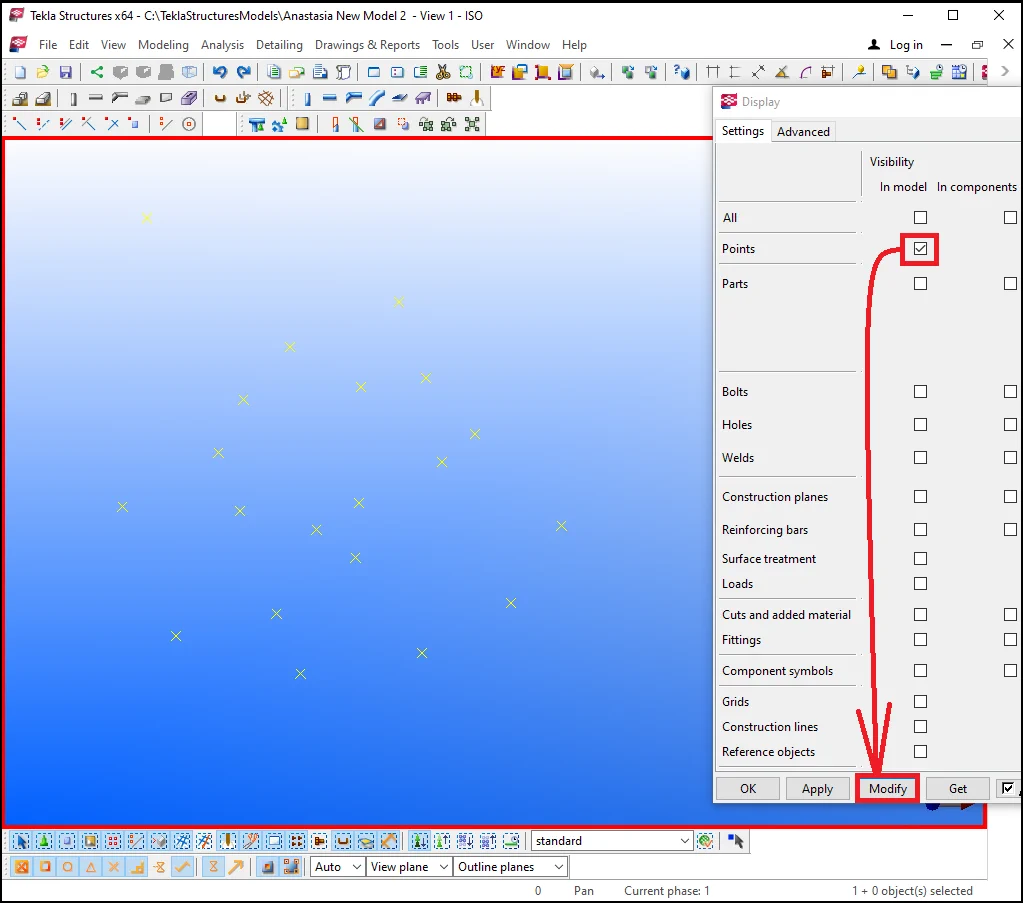
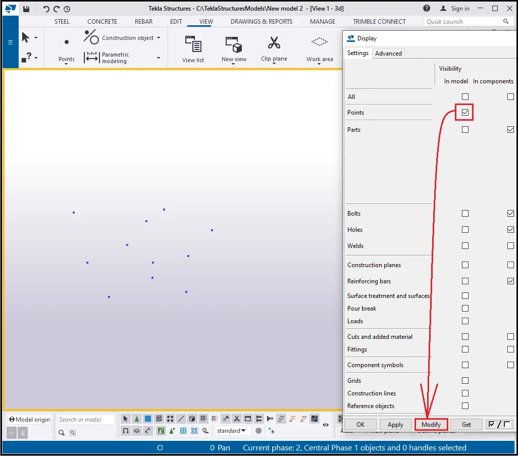
All the points become visible and do not disappear when redrawing the
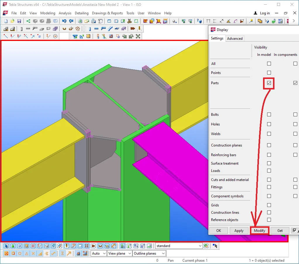
Item 3 - The " Parts" row is the tool, which allows displaying/hiding parts.
Activate the respective checkbox at the visibility “In model” column, leaving the other column's checkbox blank, and press the “Modify” button.
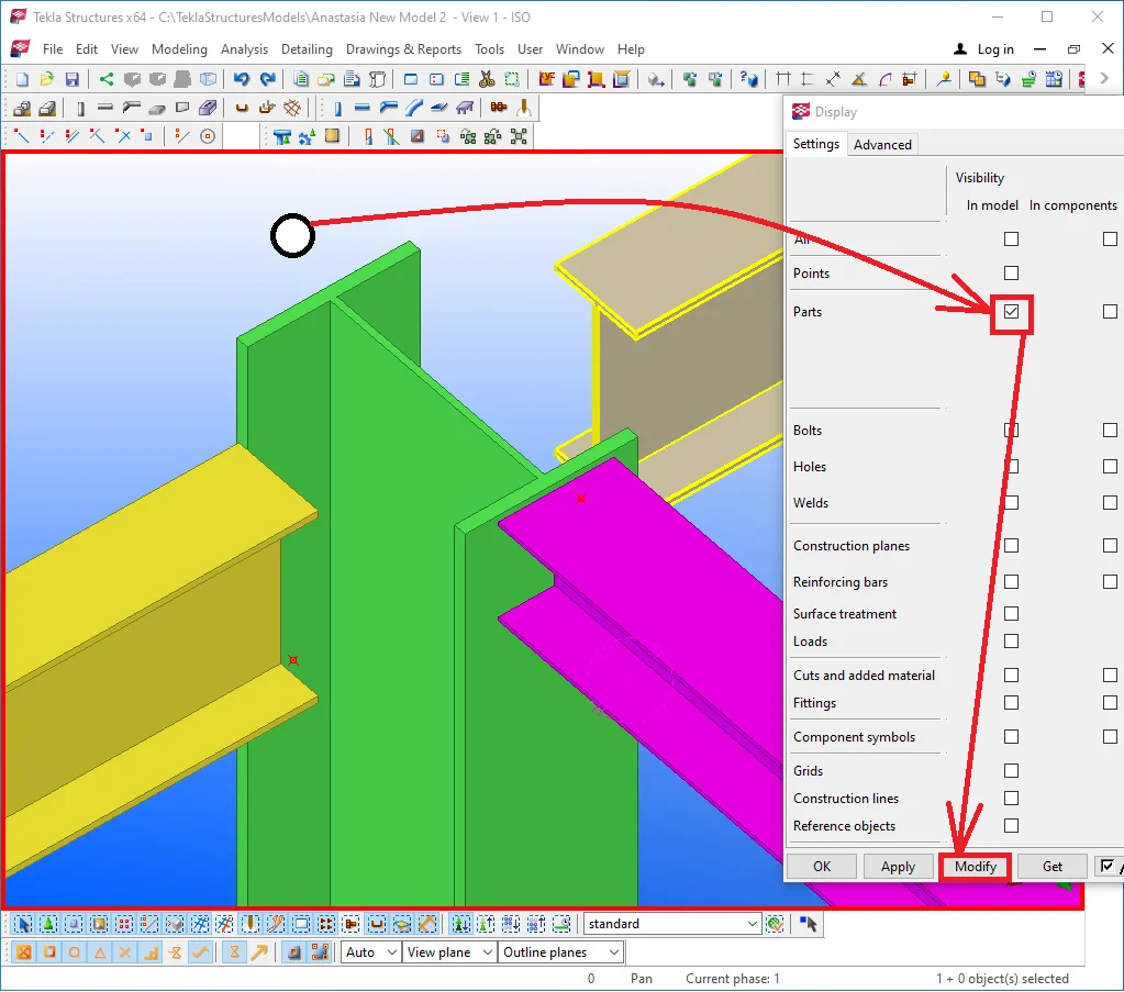
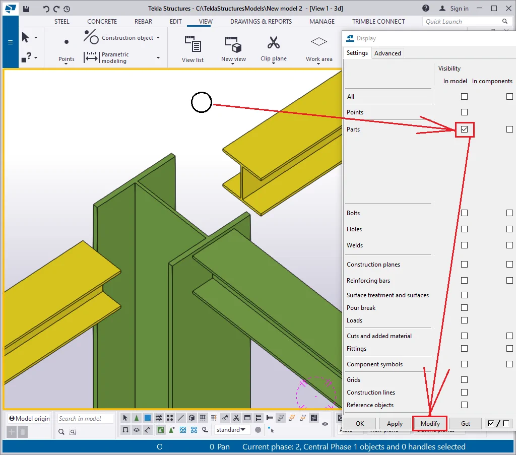
As a result, we get displayed only beams, columns, and none of the component
Activating the “Parts” checkbox, visibility “In
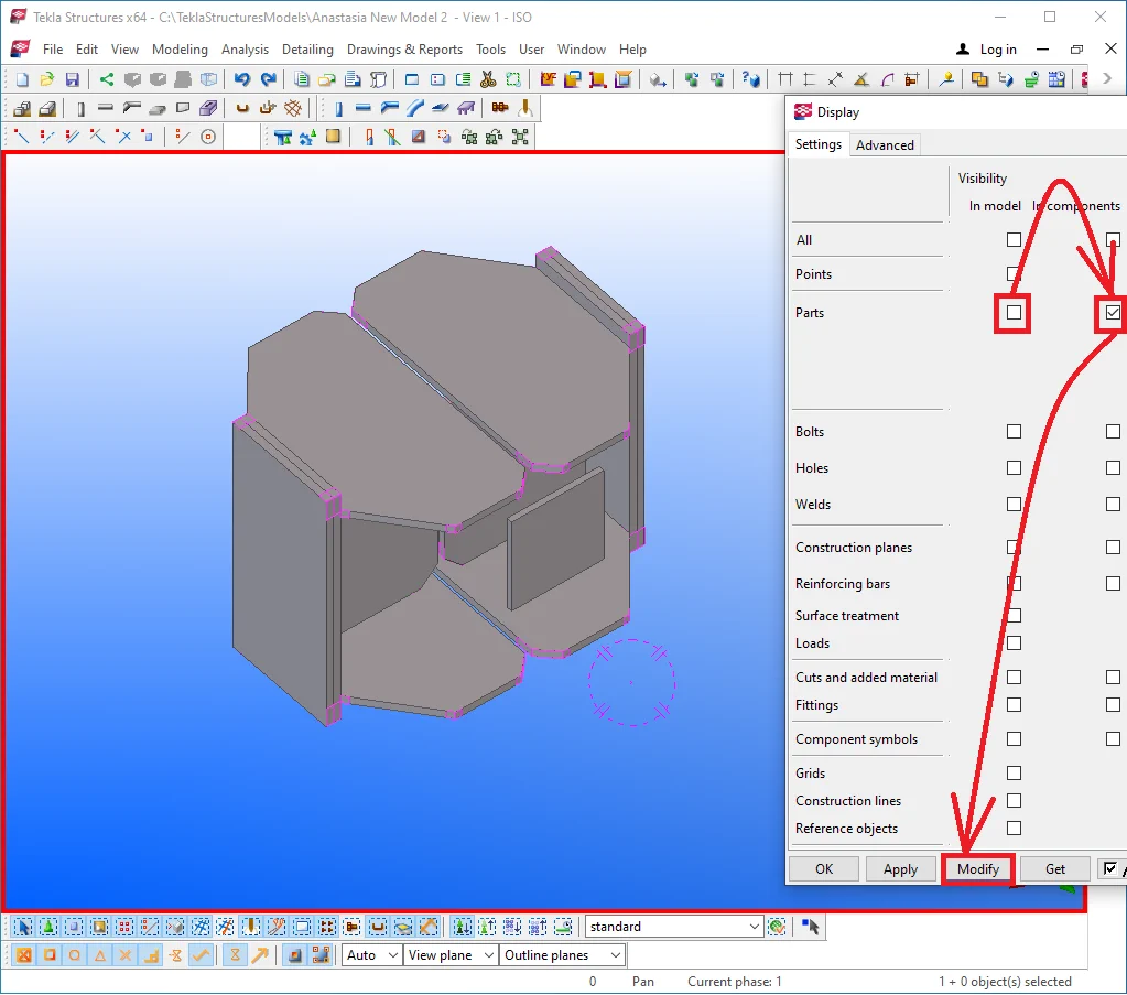
Activating both "Part" checkboxes displays all the parts of
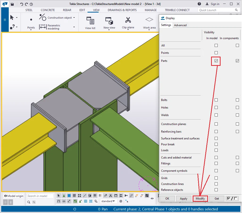
Note that bolts and other object types are still not visible.
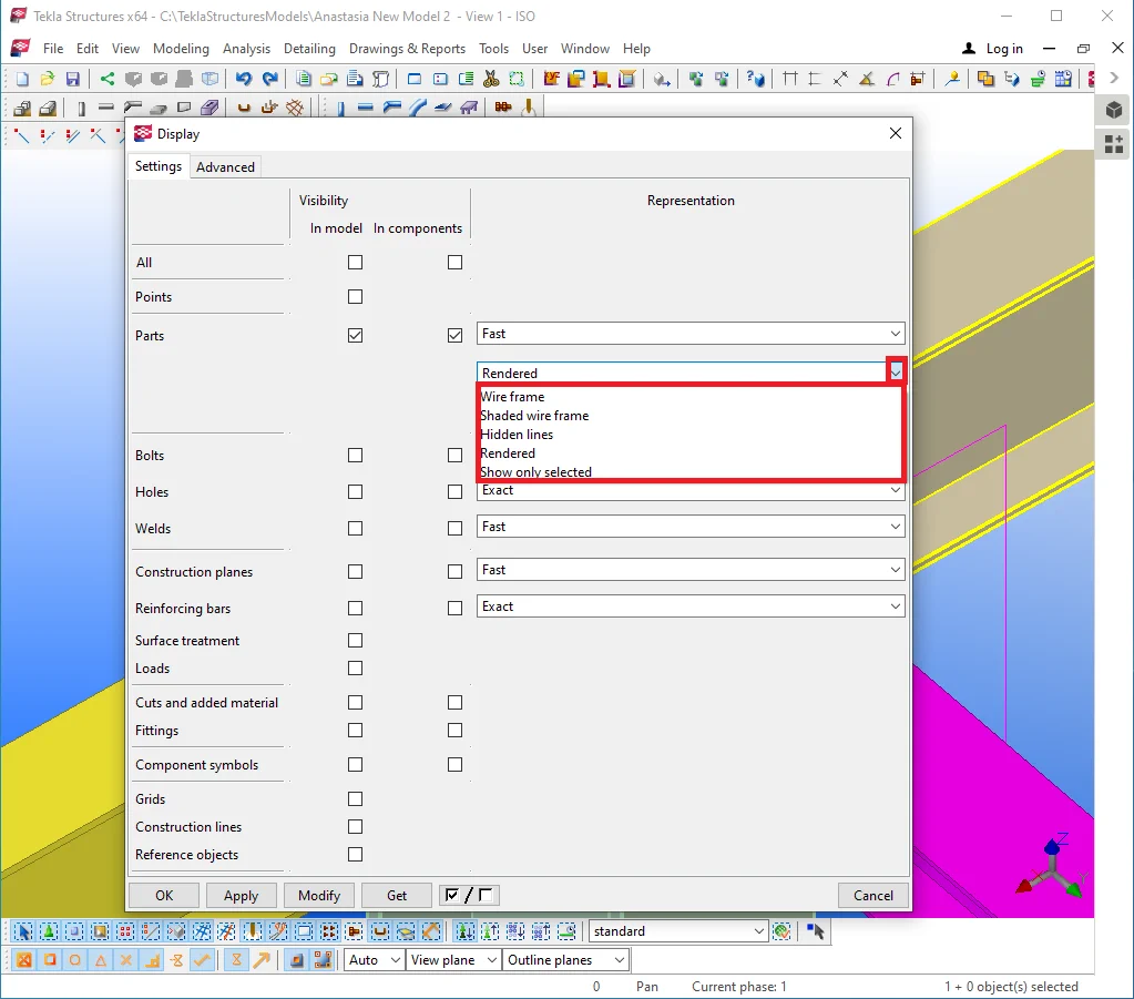
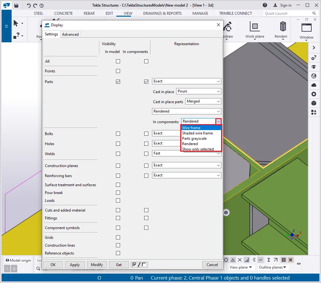
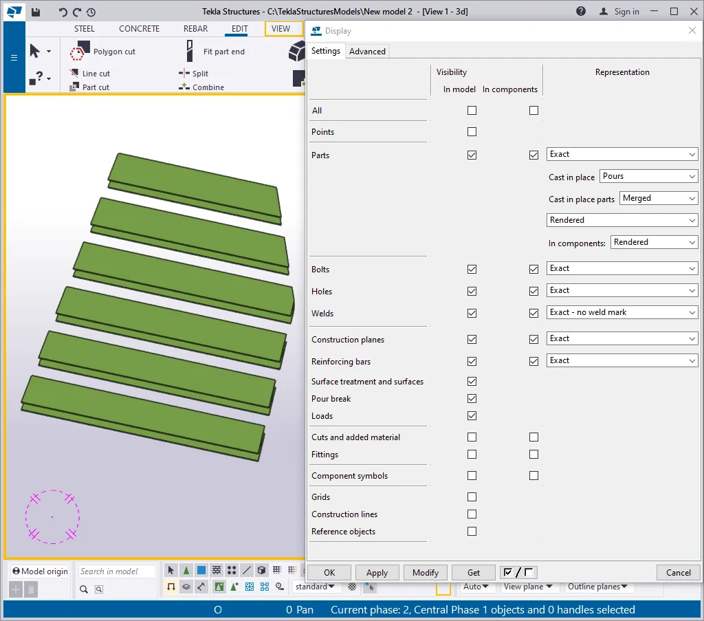
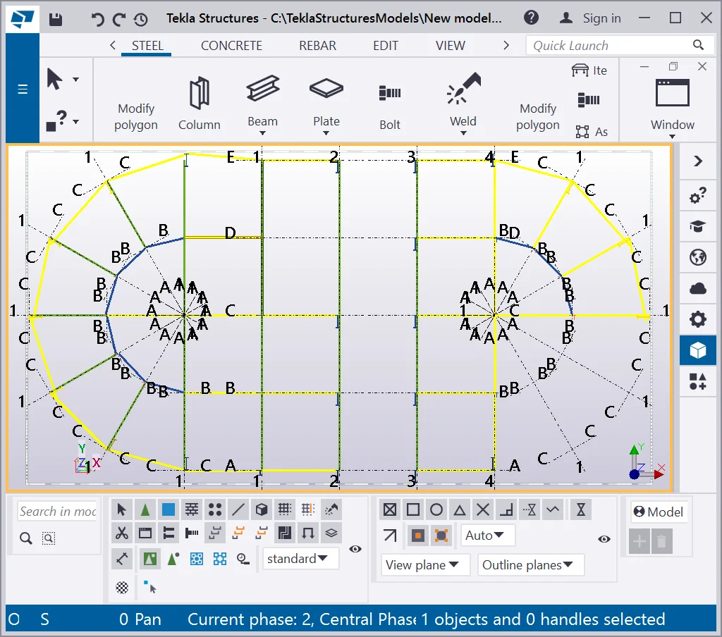
Going to the “Representation” column drop-down box, we can examine various options for the “Parts” rendering. Set up the box value at “Reference line” and press the “Modify” button.

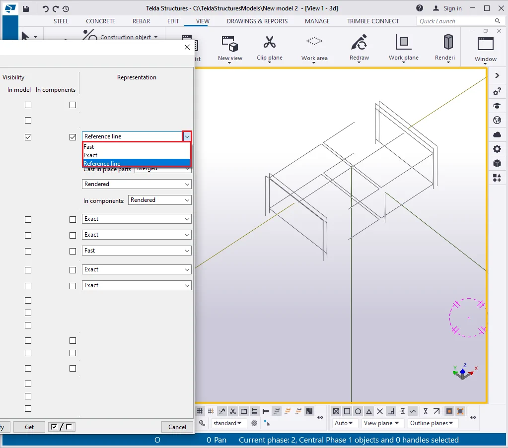
Now all the objects are represented as lines. This regime is essential when designing big projects. Though nowadays it is of no use due to the high operational speed of modern computers. Switch the representation type to “Fast”.

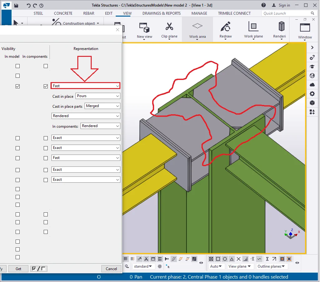
All the parts are displayed in a standard way, except for the fact there is no painting at the part’s edges (not applicable for the new TS interfaces). Previously, setting up the “Fast” representation mode was a reasonable solution when PC capacity was not enough for processing significant volumes of geometry. For modern PCs it is of no relevance using the “Fast” representation mode, thus we will always set this field as the “Exact” option.
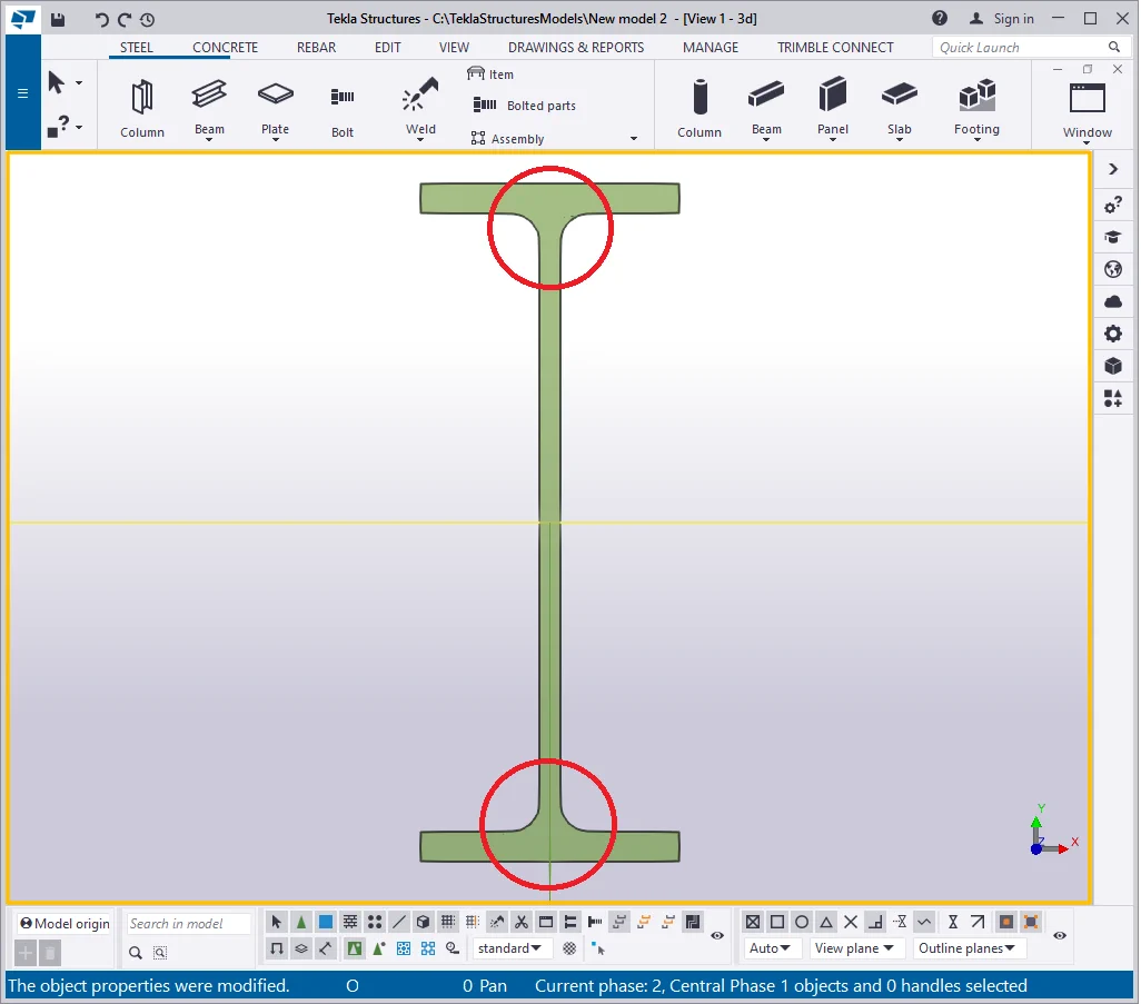
There is one more representation mode available, providing a more detailed rendering for rounding radiuses in profiles, but unfortunately, it is not accessible at the “Display" menu for selecting.
For this purpose we can proceed in the following way: select the objects required and in the right-click menu enable the “Show with exact lines” tab while simultaneously holding on the Shift key pressed. This regime can be enabled permanently at the TS advanced settings, but it is not recommended from the practical side, as it impedes snapping to the profile faces.
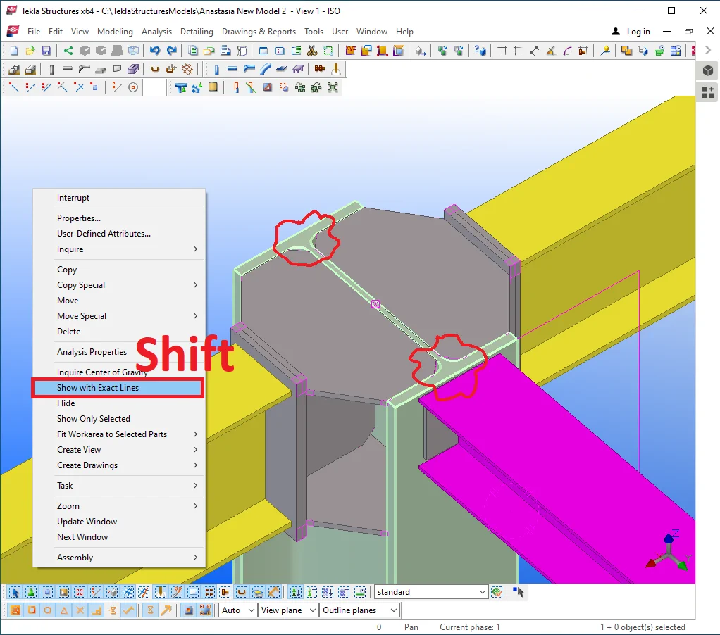
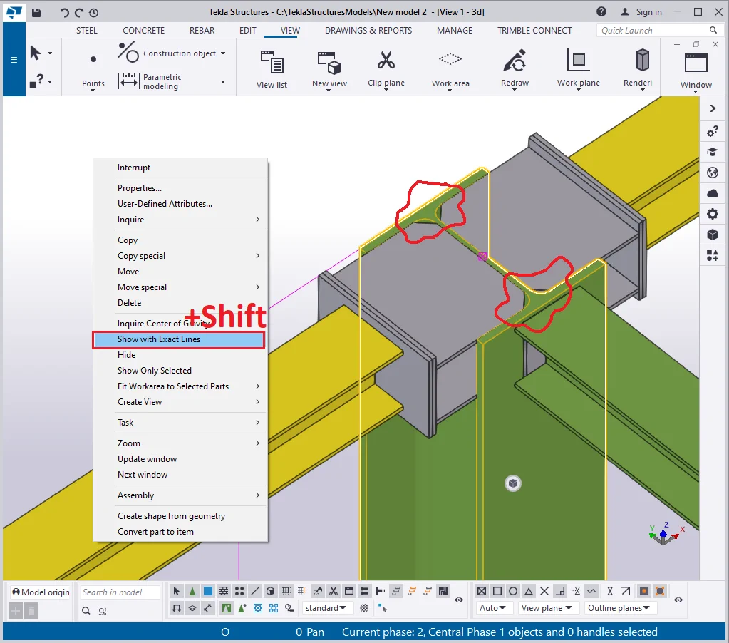
To disable the "Show with exact lines" regime, proceed the same way as when activating it: in the right-click menu, select the respective tab without holding on the Shift key pressed.

Item 3.1 - The "Current representation mode" box. Go to the list of the available parameters. These are exactly the options which we exercise when using the hotkey combinations of Ctrl+1,Ctrl+2,Ctrl+3,Ctrl+4,Ctrl+5.
Test these out by yourself.

Item 3.2 - The "C urrent representation mode of the parts in components" box. Go to the list of the available parameters. These are exactly the options that we exercise when using the hotkey combinations of Shift+1, Shift+2, Shift+3, Shift+4, Shift+5. Test these out by yourself.

Item 4 - The " Bolts" row. T hese checkboxes allow displaying/hiding bolts ( not applicable to the bolt holes, as these are a different object type).
Enable the bolts checkboxes.
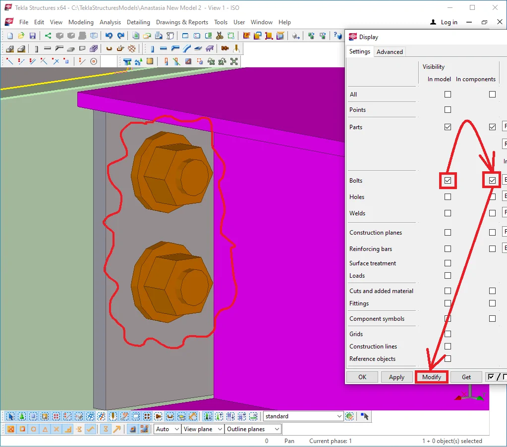
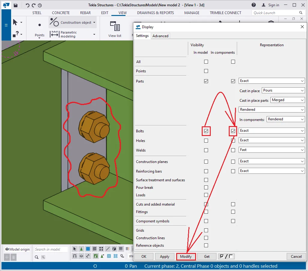
In the adjacent box, there are available several representation modes for bolts. Select the option “Fast”. Similar to the above case, the “Fast” representation mode uses much fewer PC resources.
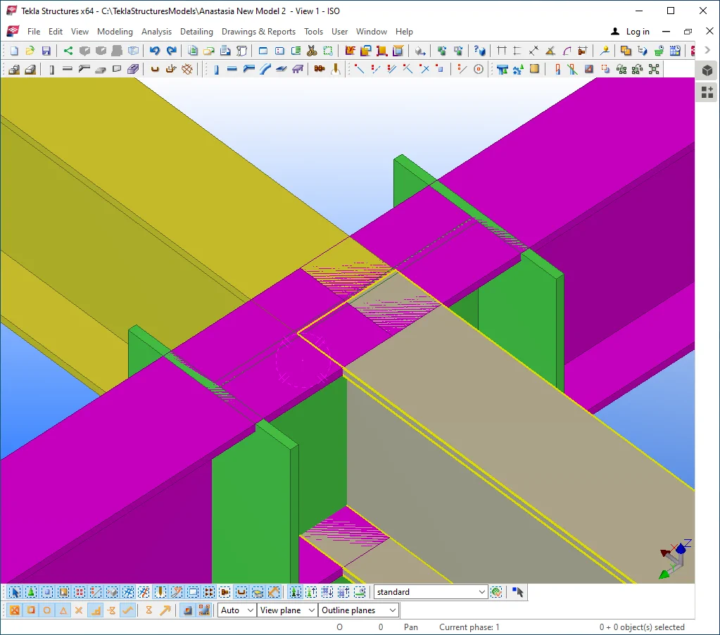
Tekla Structures v21.1 |
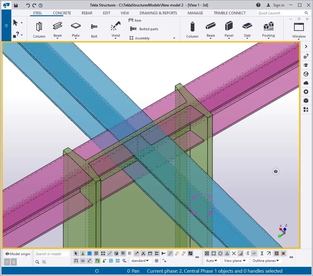
Tekla Structures v2021 |
|
|
|
Restore the representation mode to the “Exact” one.
Item 5 - The "Holes" raw - All the predrilled holes in the TS are done by using the “Create bolted connection” tool. It is strictly forbidden and is a huge error creating predrilled holes using the “polygon cut” or the “Line cut” tools.
Thus the “Holes” checkbox allows displaying/hiding bolt holes.
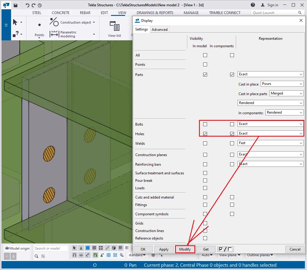
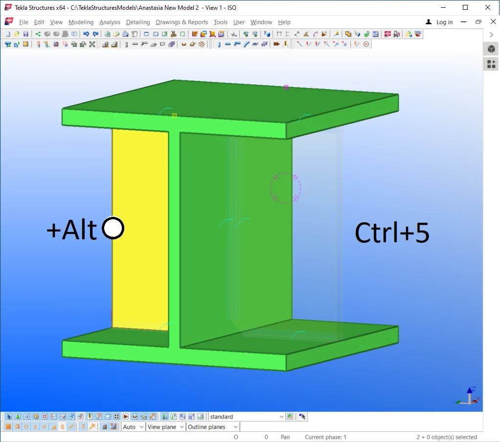
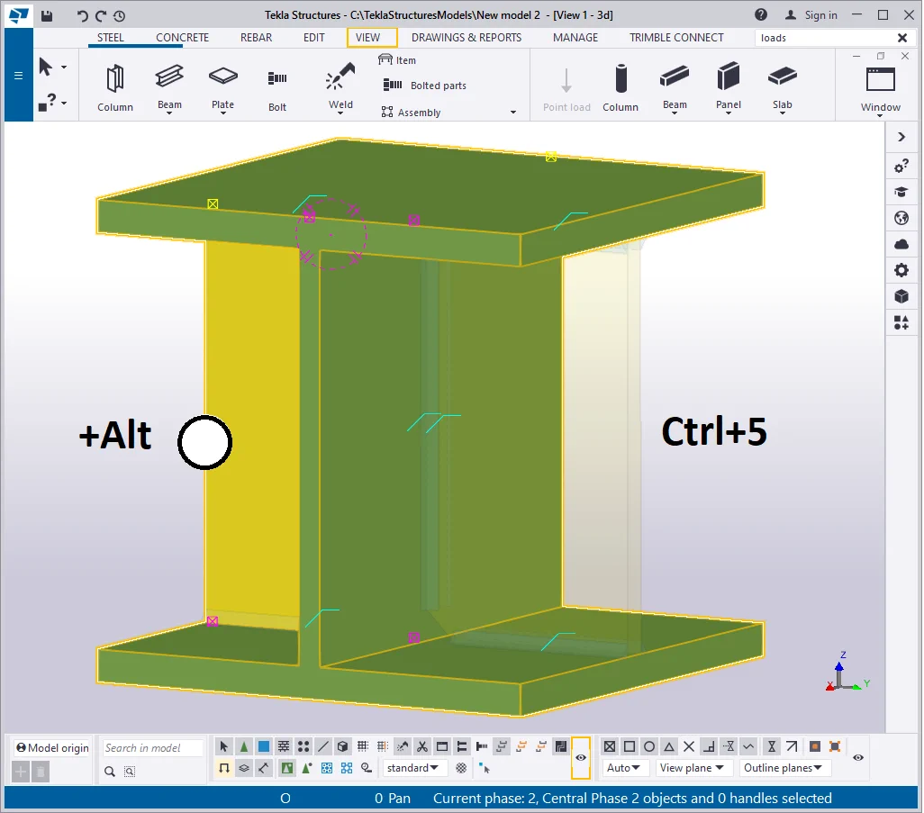
Note that holes in the TS are not considered the absence of material but as a special material type. Thus we can not see the holes themselves and the objects behind them. Toggling between various display modes offers various color visibility options, where the Ctrl+5 Shift+5 provides the best visibility for the bolt holes.

Similar to the bolts, bolt holes can be rendered under various representation
Try using the “Fast” type. As you can see, the holes
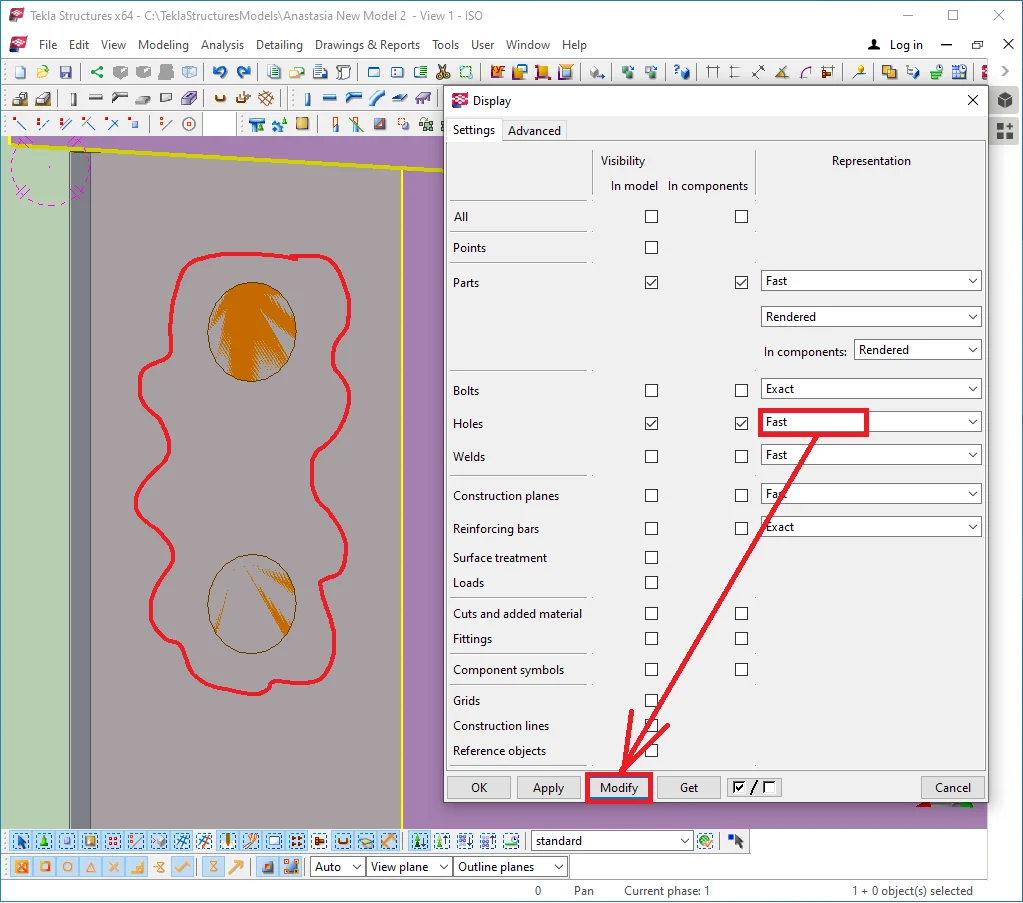
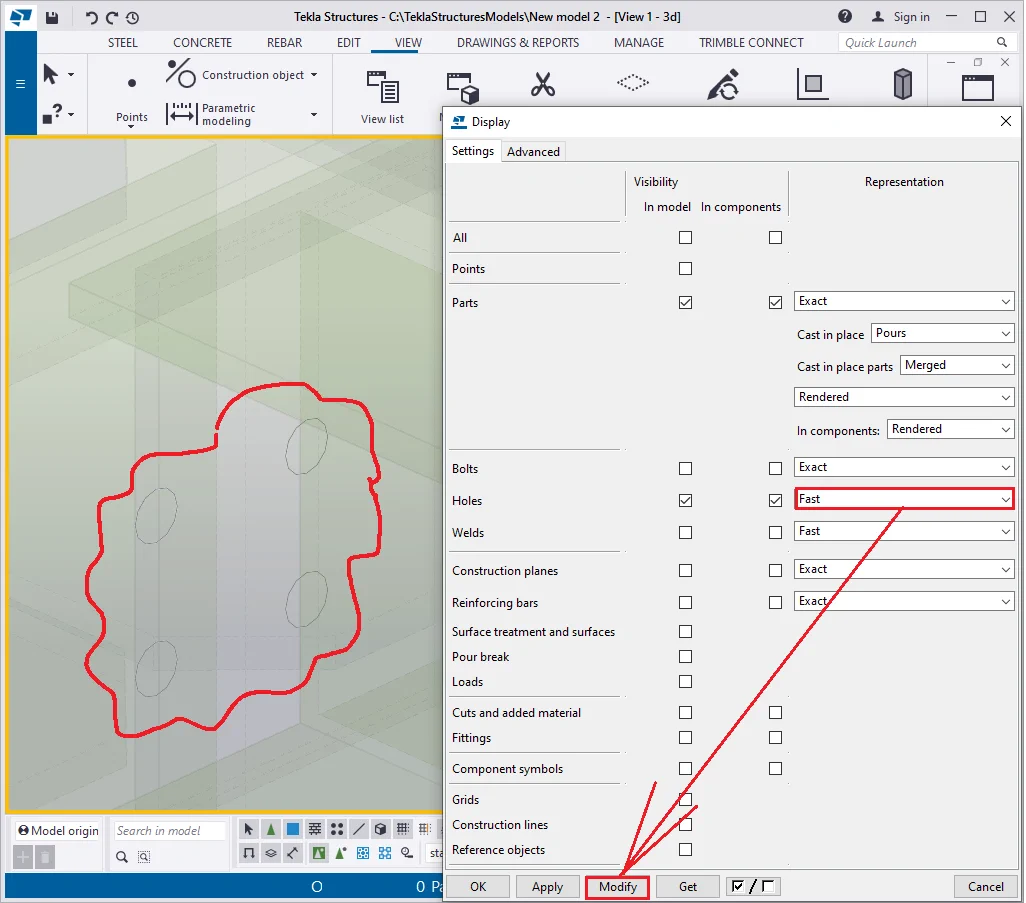
The “Fast” and the “Exact slotted holes” regimes
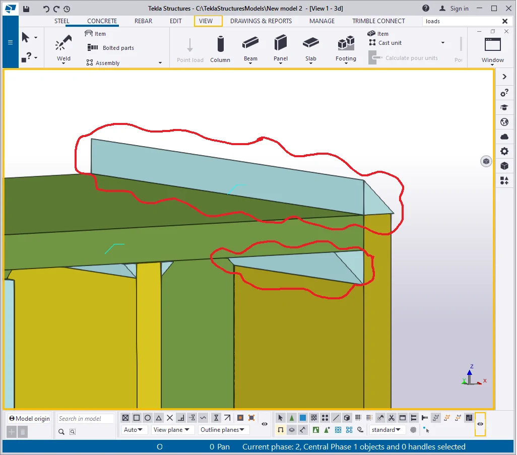
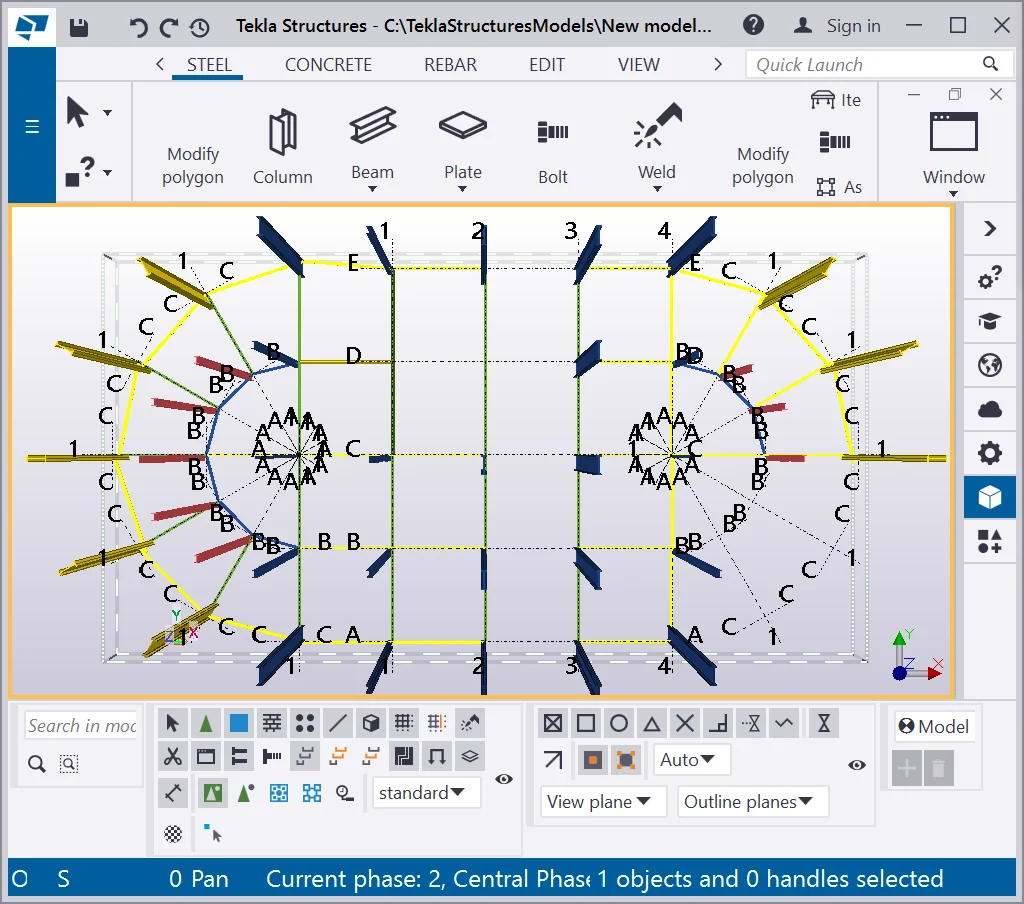
Item 6 - The "Welds" row. This checkbox displays/hides welded seams in the model. Let’s activate the checkboxes and set them up at the “Exact” representation mode to get their location.

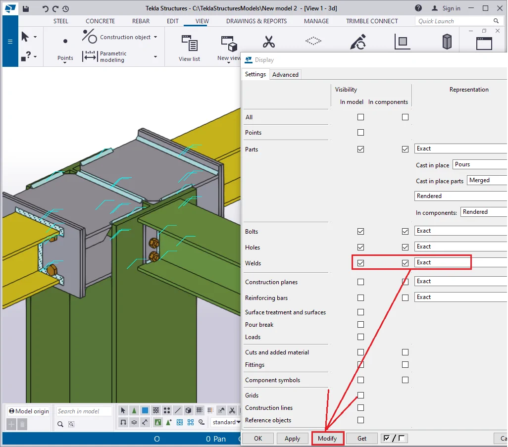
As you can see, each welded seam is marked up with a cloud and is shown as a three-dimensional body. In general practice, there are many welds thus all the correspondent clouds clutter up the model view.
Let’s display the welds as a three-dimensional body with no cloud
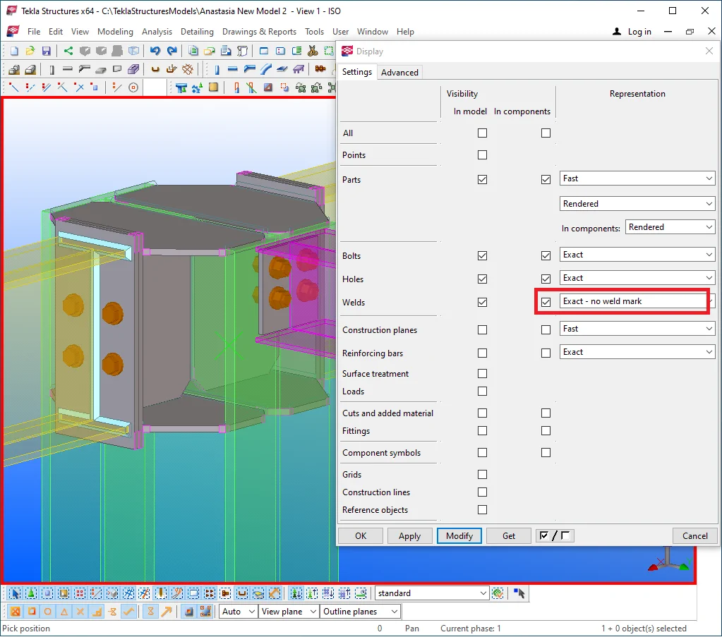
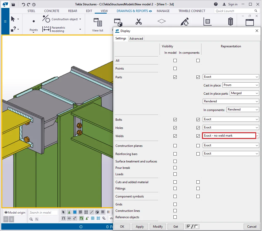
All the clouds were automatically hidden. The “Fast” representation type displays only clouds, without depicting the welds' three-dimensional bodies. In practice, usually, it is convenient to hide the weld bodies by disabling all the checkboxes.
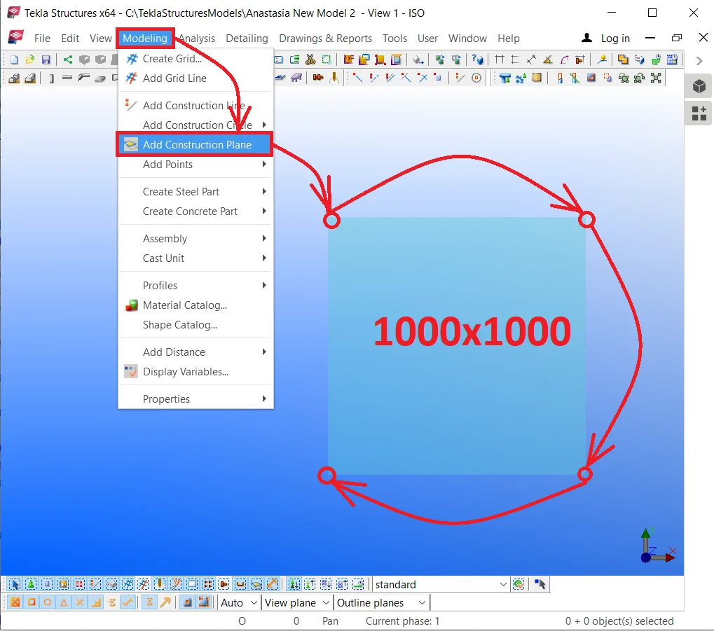
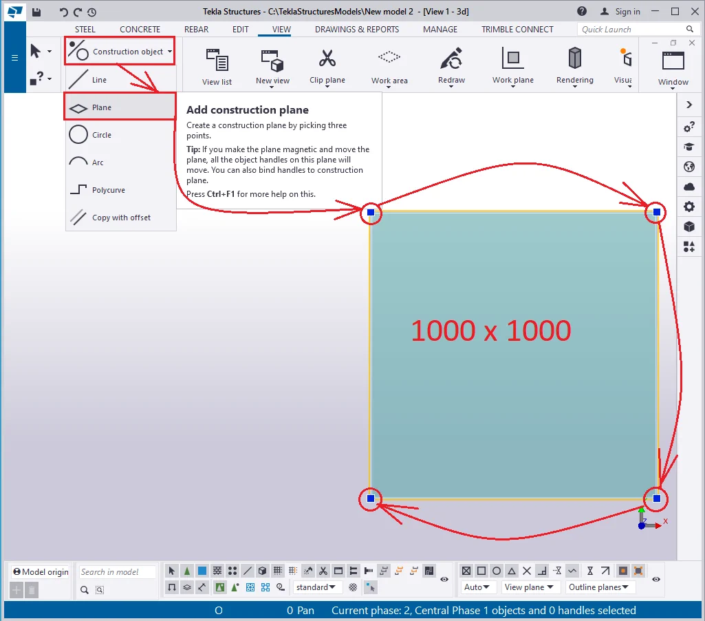
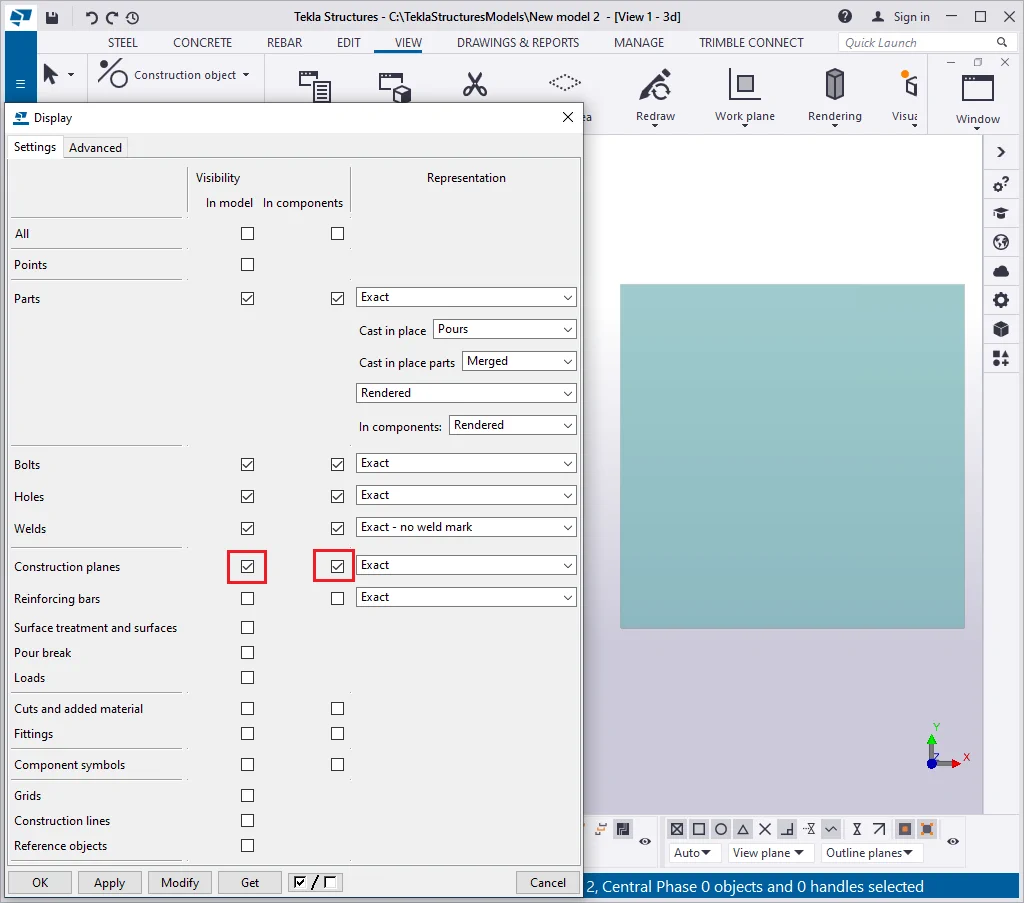
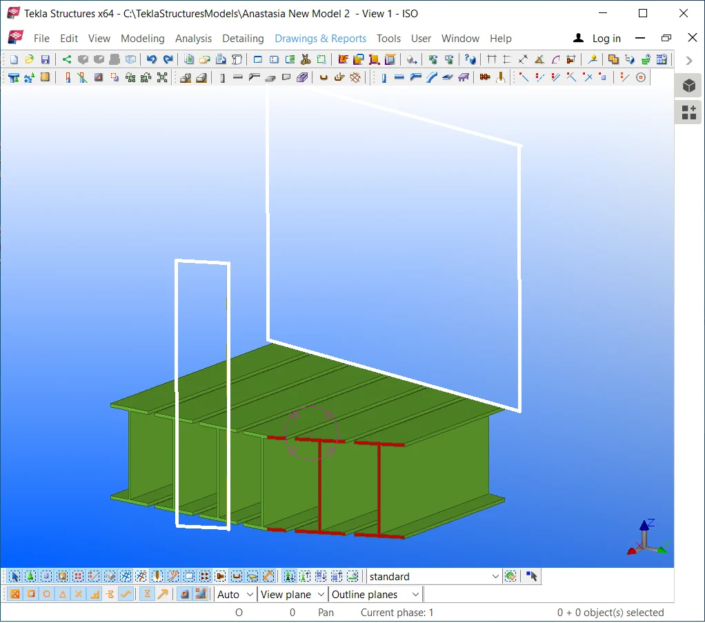
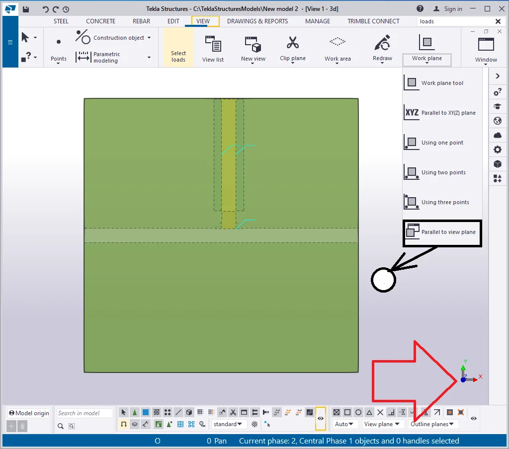
Item 7 - The "Construction planes" checkboxes allow displaying/hiding construction geometry objects. Create an object at any place of the model by referring to the below picture:
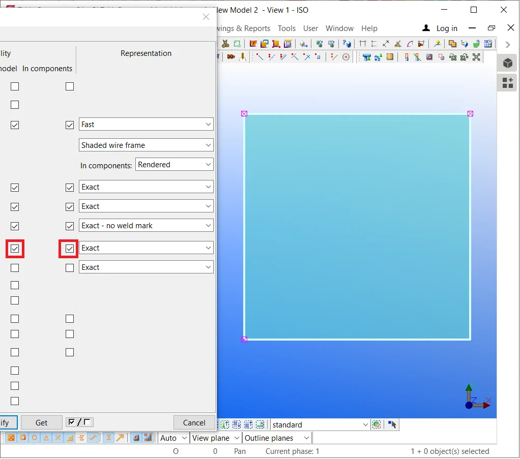
As we have just created the object, it is still visible in the view. Select


As the correspondent checkboxes are not activated, redrawing the view
Now, activate the "Construction planes" checkboxes.
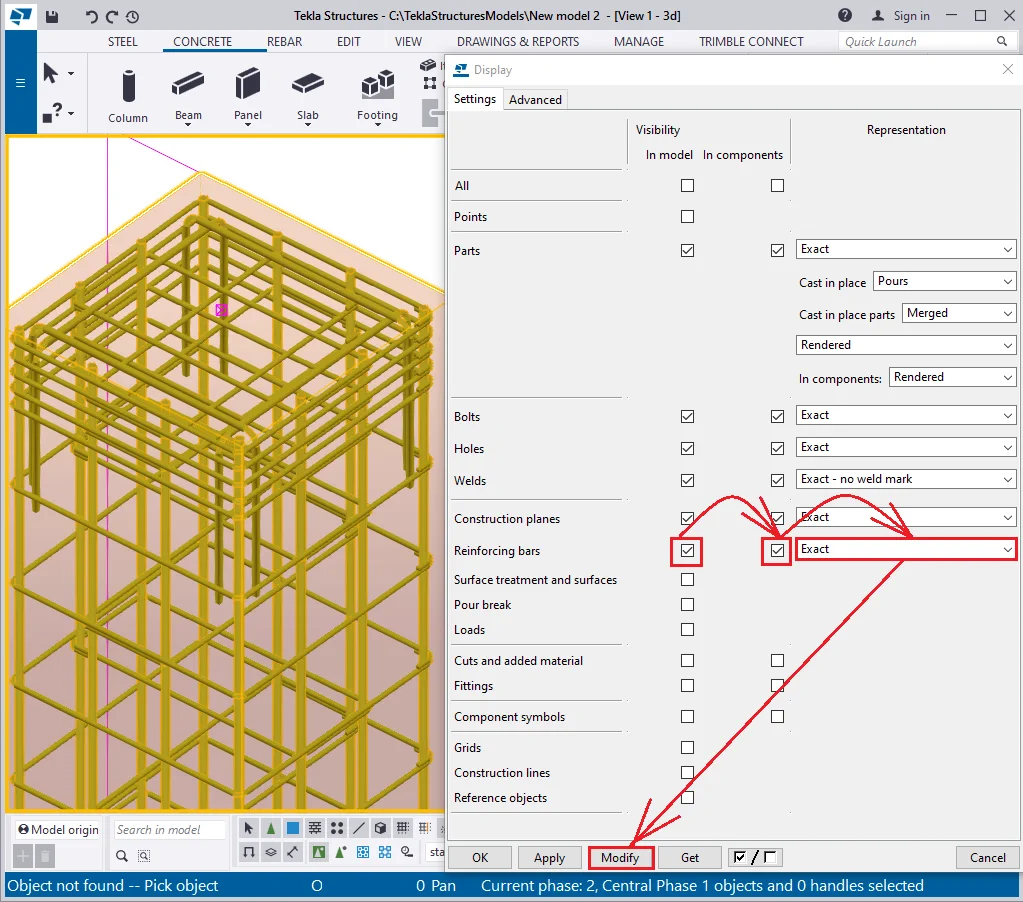
Item 8 - The "Reinforcing bars" checkbox relates to displaying/hiding the reinforcing bars in the objects.
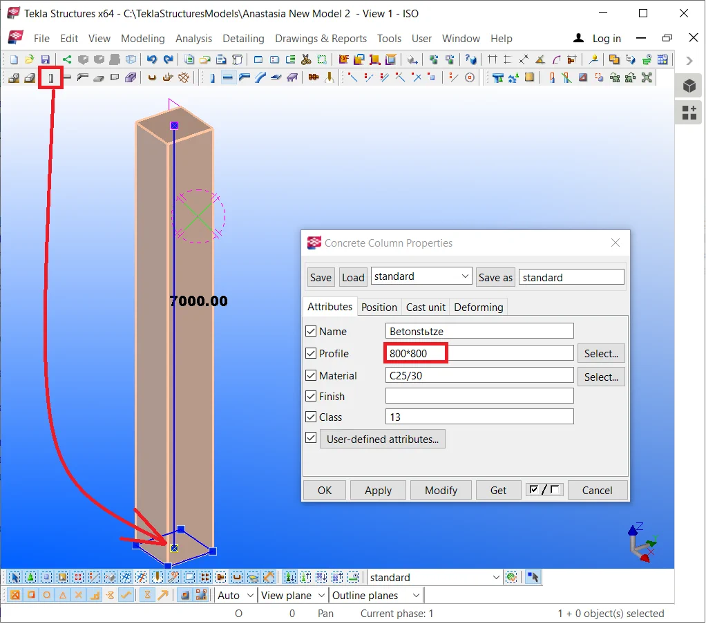
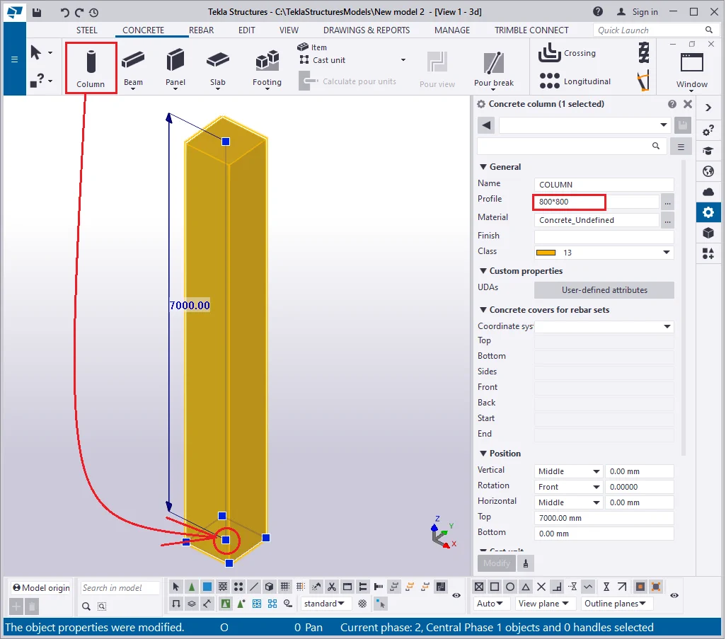
Create an arbitrary concrete column of the 800*800 profile.
Go to the “Applications and components” catalog by enabling the Ctrl+F hotkey combination and select component No 83- “Rectangular column reinforcement” and apply it to the column by executing a left-click on it.


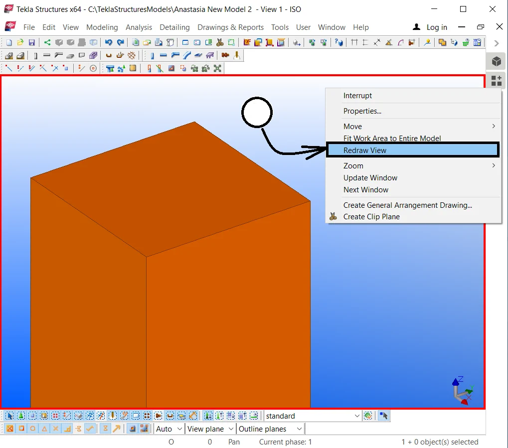
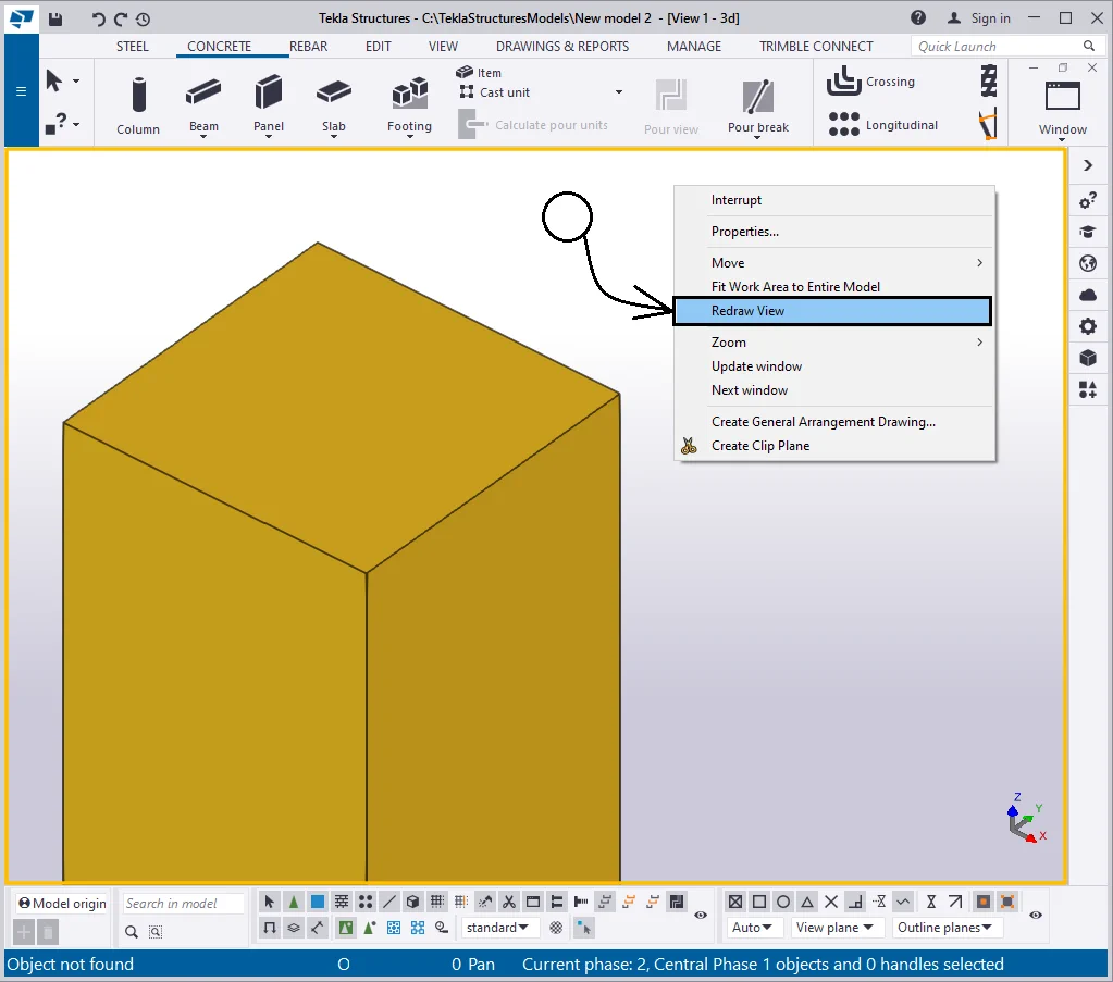
In the right-click menu, select the “Redraw view” tab, and
In the “Display” menu, activate the respective checkboxes
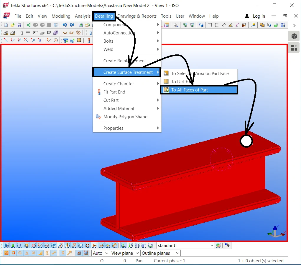
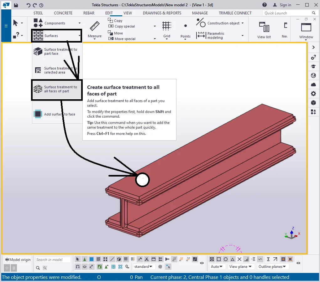
Item 9 - The “ Surface treatment and surfaces” checkboxes refer to displaying/ hiding surface treatments.
Create a beam of an arbitrary profile and 1000 mm length.
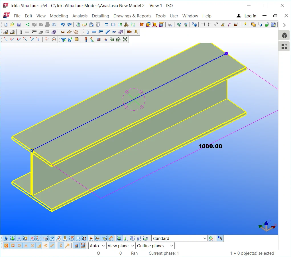
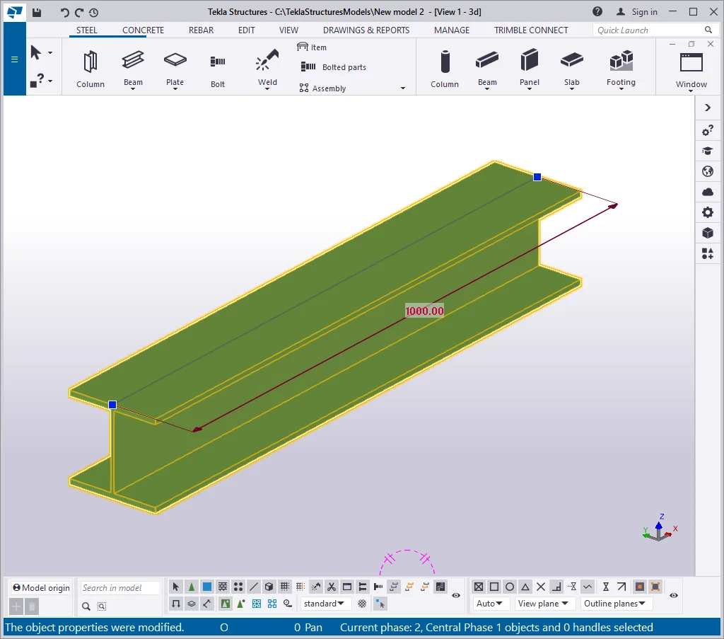
Create surface treatment at all faces of the beam.
Redraw the view according to its current settings.

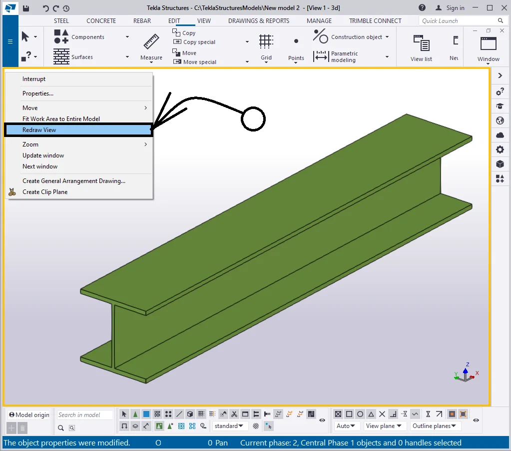
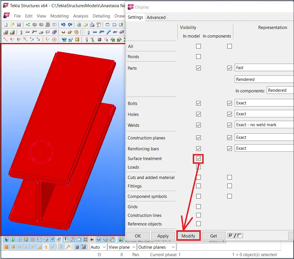
The surface treatment object was hidden. Go to the “Display” menu of the “View properties” and enable all the respective surface treatment checkboxes.
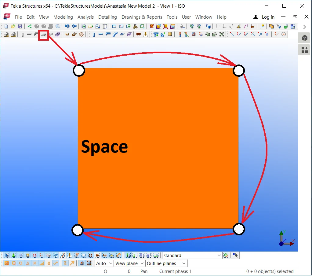
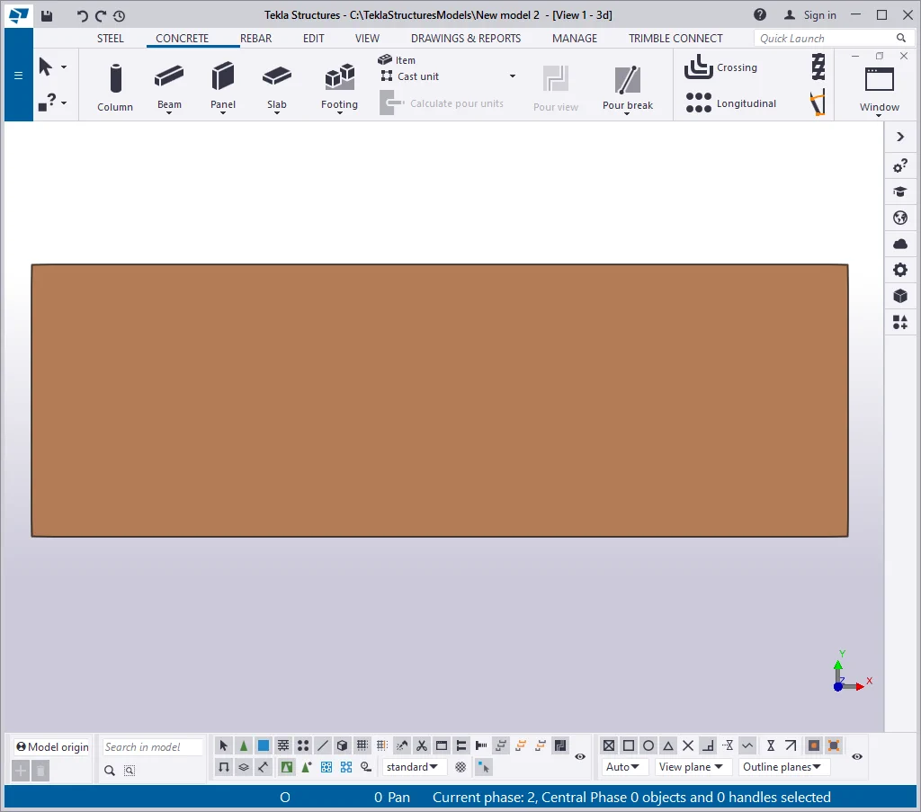
Item 10 -The " Pour break" checkbox displays/hides the junctions between concrete elements.
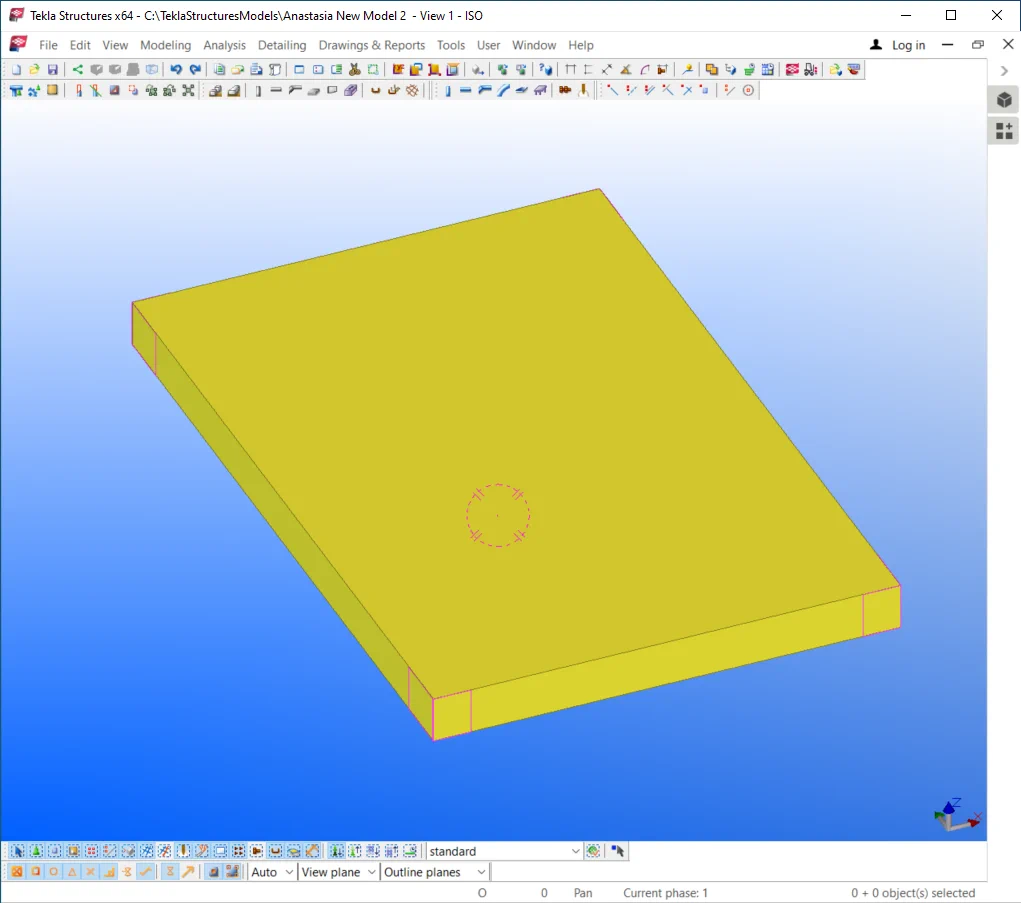
Create a concrete slab with dimensions of 1000 x 1000 mm.
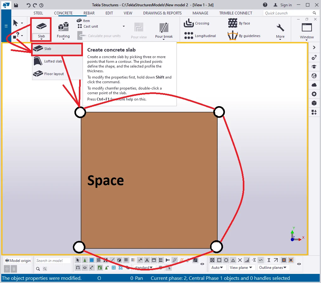
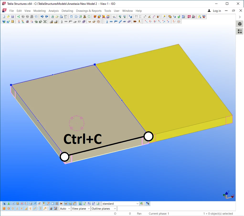
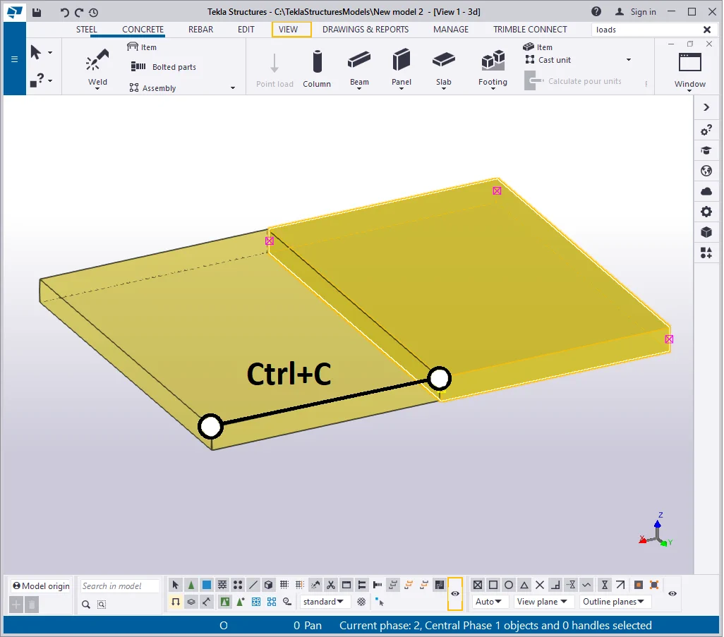
Copy the object (Ctrl+C) twice in the way that the copied objects have
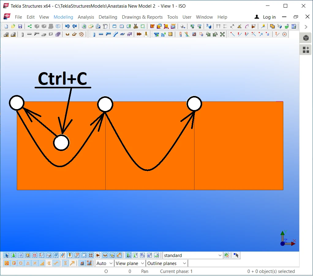
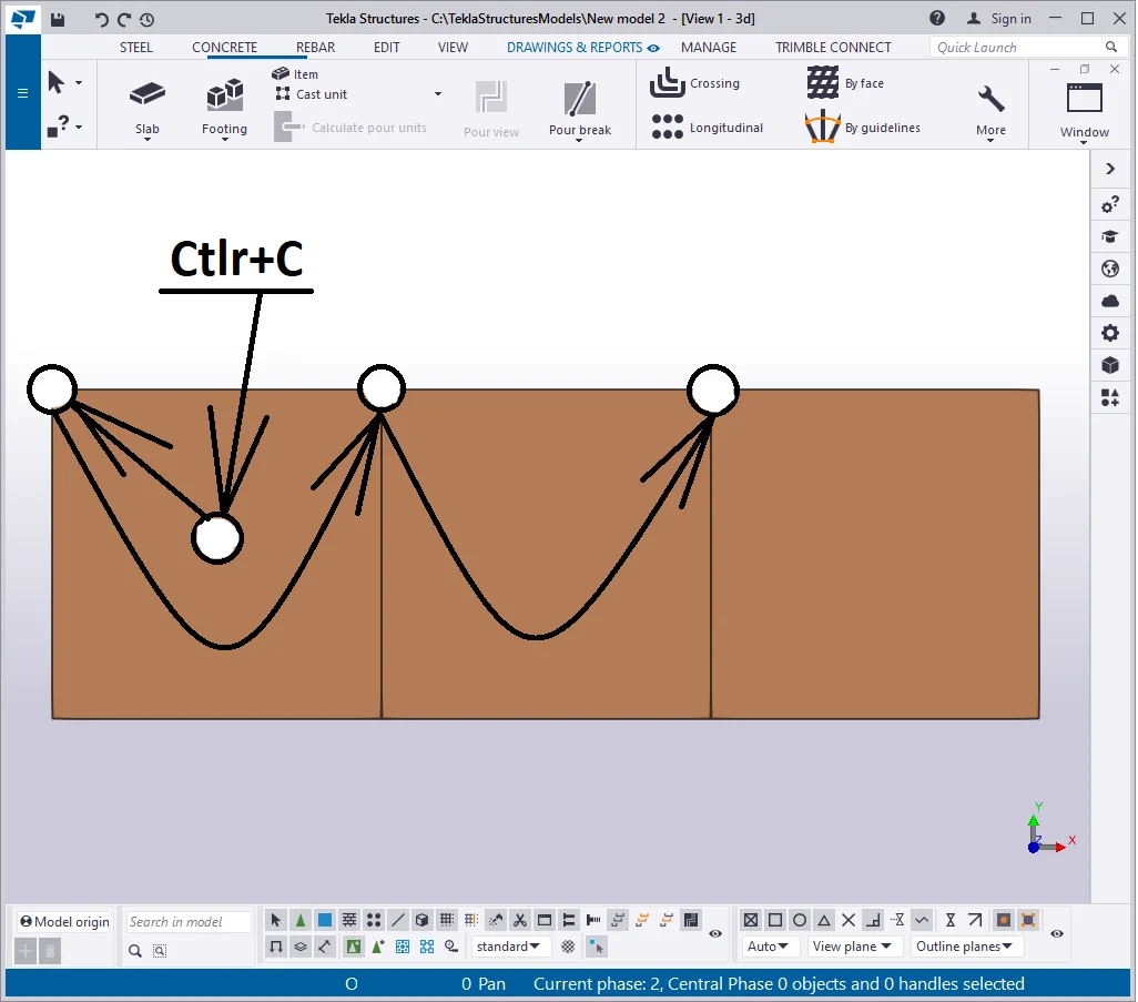
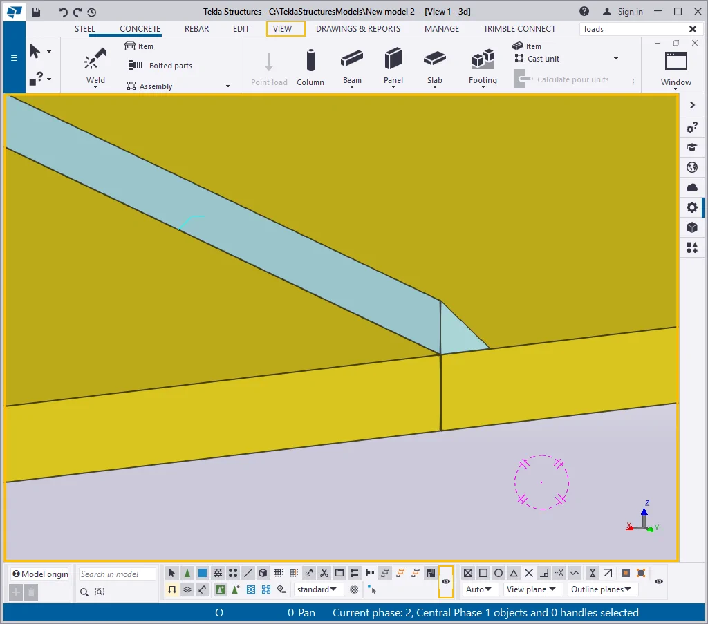
Displaying junction lines in the concrete objects is not a correct way,
The present TS version does not allow hiding junction lines between concrete elements.
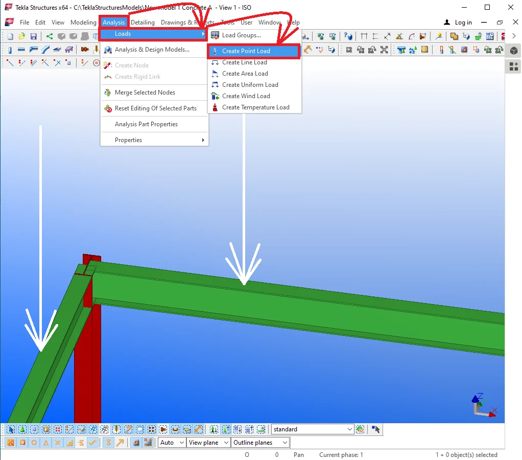
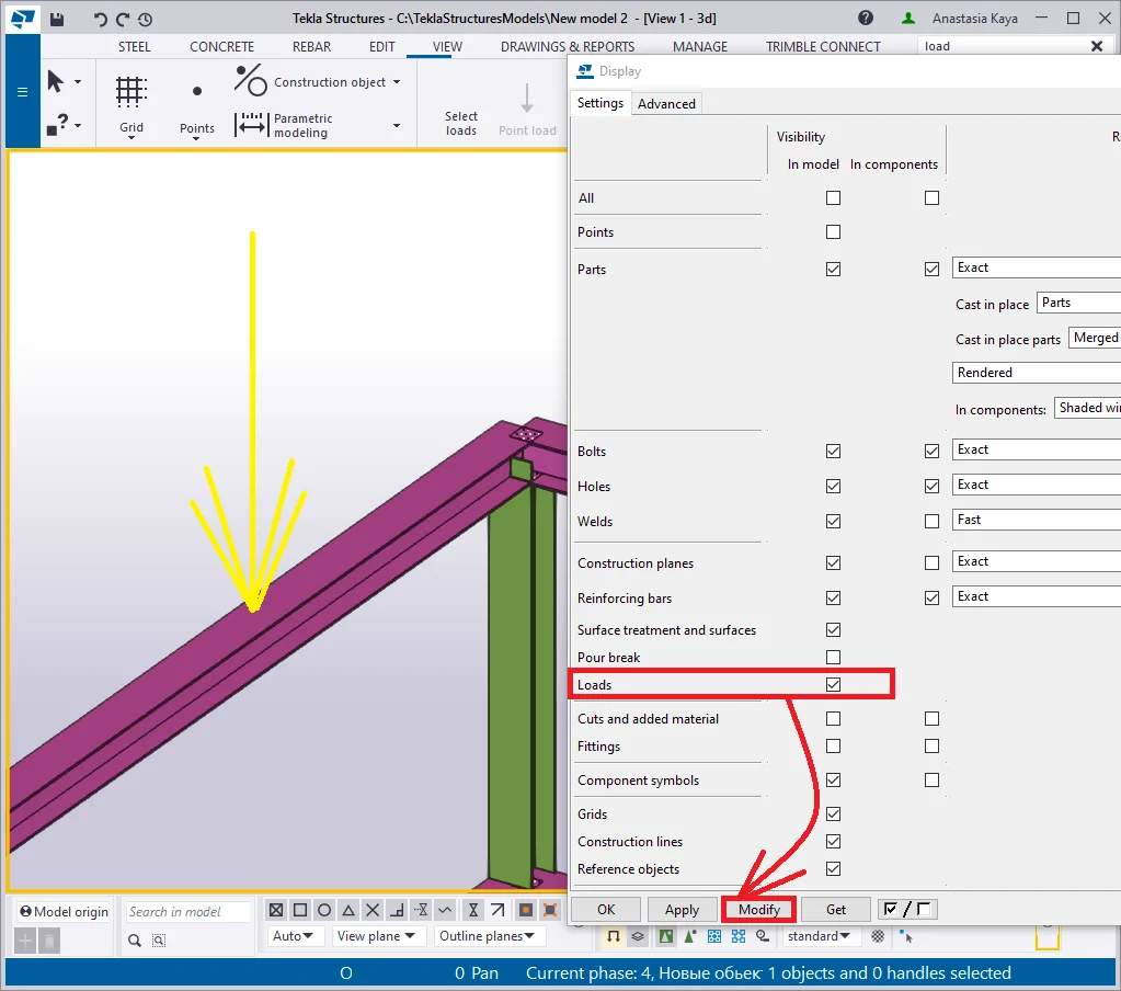
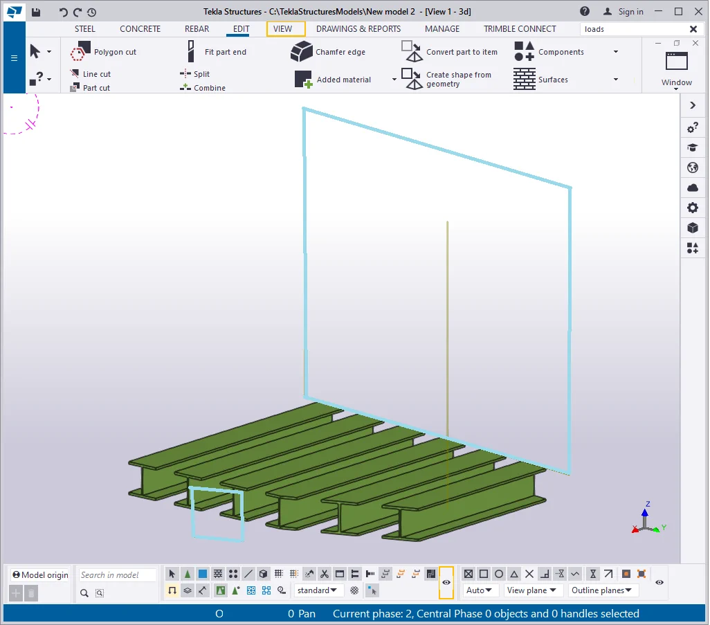
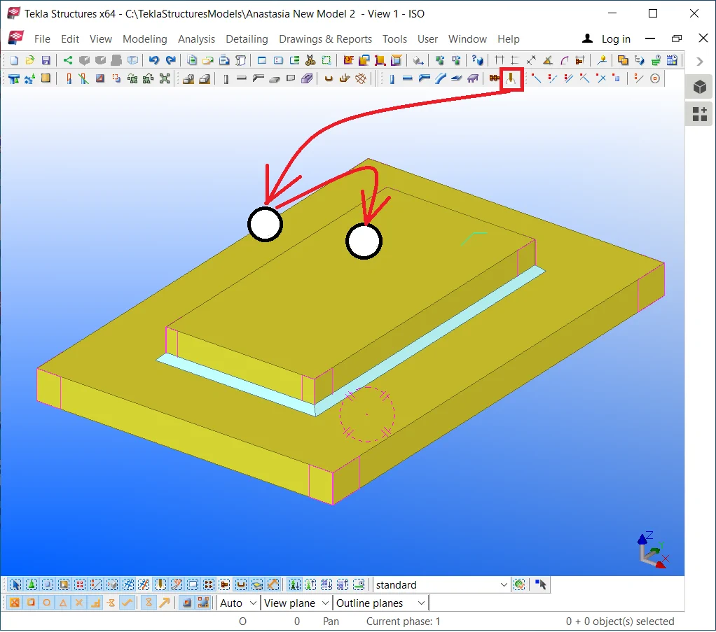
It em 11 - Loads - represent a definite object type necessary when working with the calculation models created in the TS ( we will examine in detail these types of models at the respective section). Create several point loads by enabling the respective tool and indicating the point loads by a right-click in the model. You can simultaneously indicate several loads at various locations.
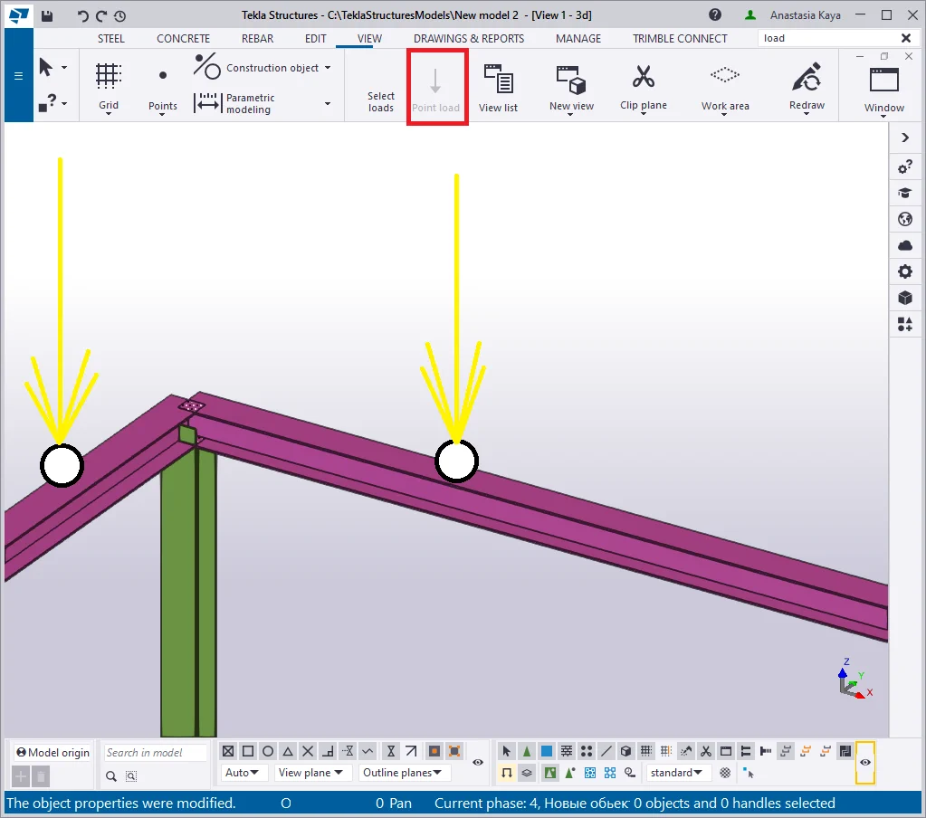
As we have just created the point loads, these are still visible in the model. However, redrawing the view hides the point load objects. Redraw the view by enabling the respective tab from the right-click menu.


Thus all the point load objects are hidden off the view. Restore rendering this object type by enabling the respective check box at the view properties menu.

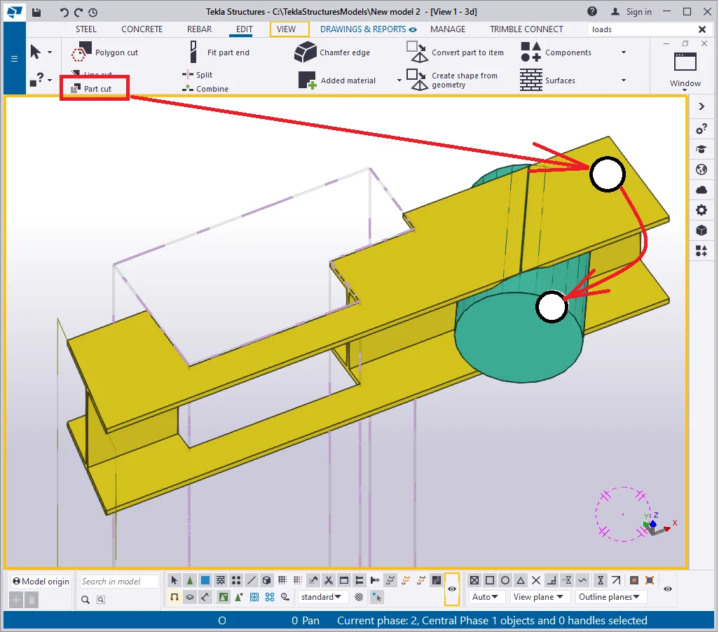
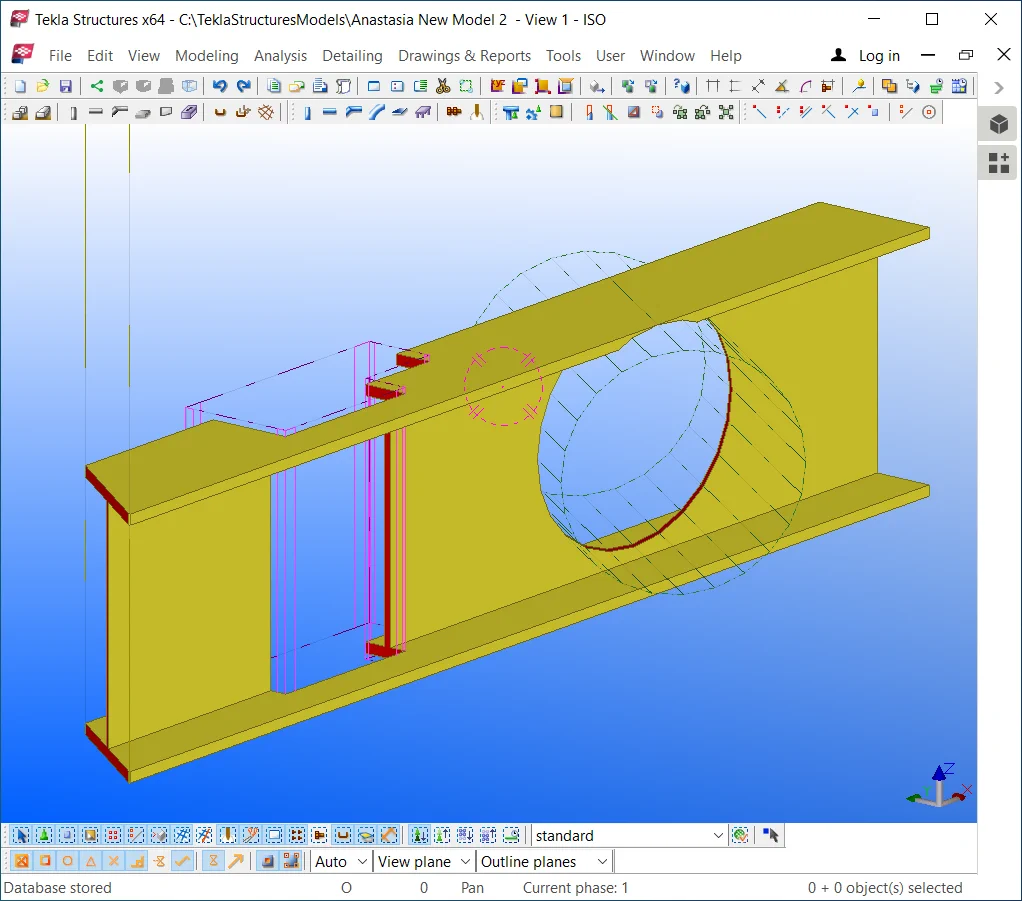
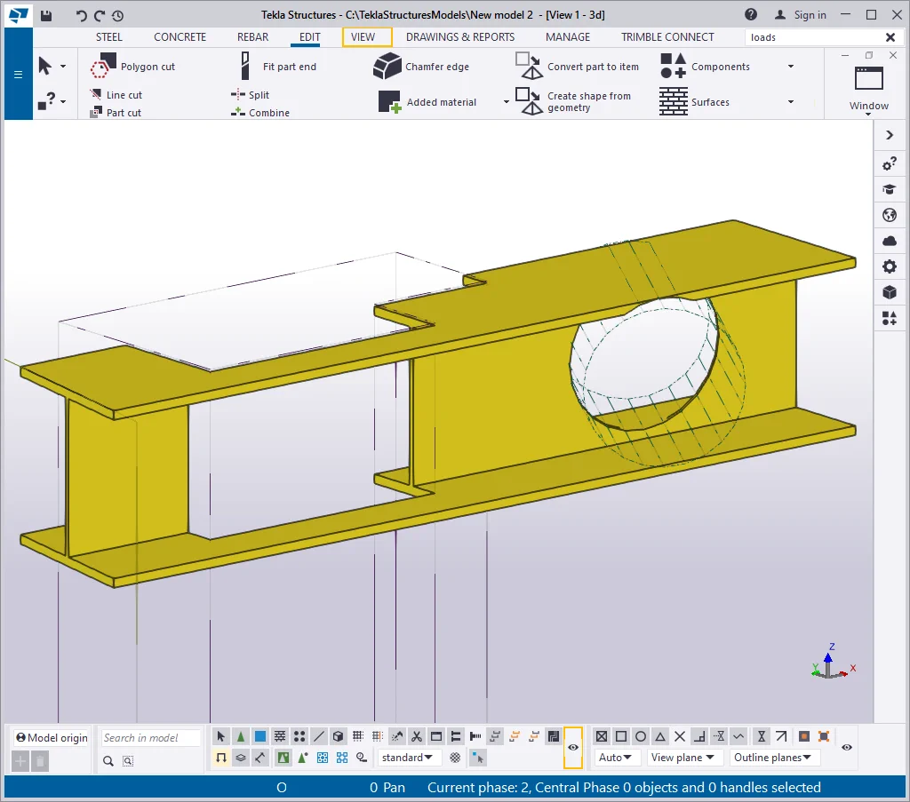
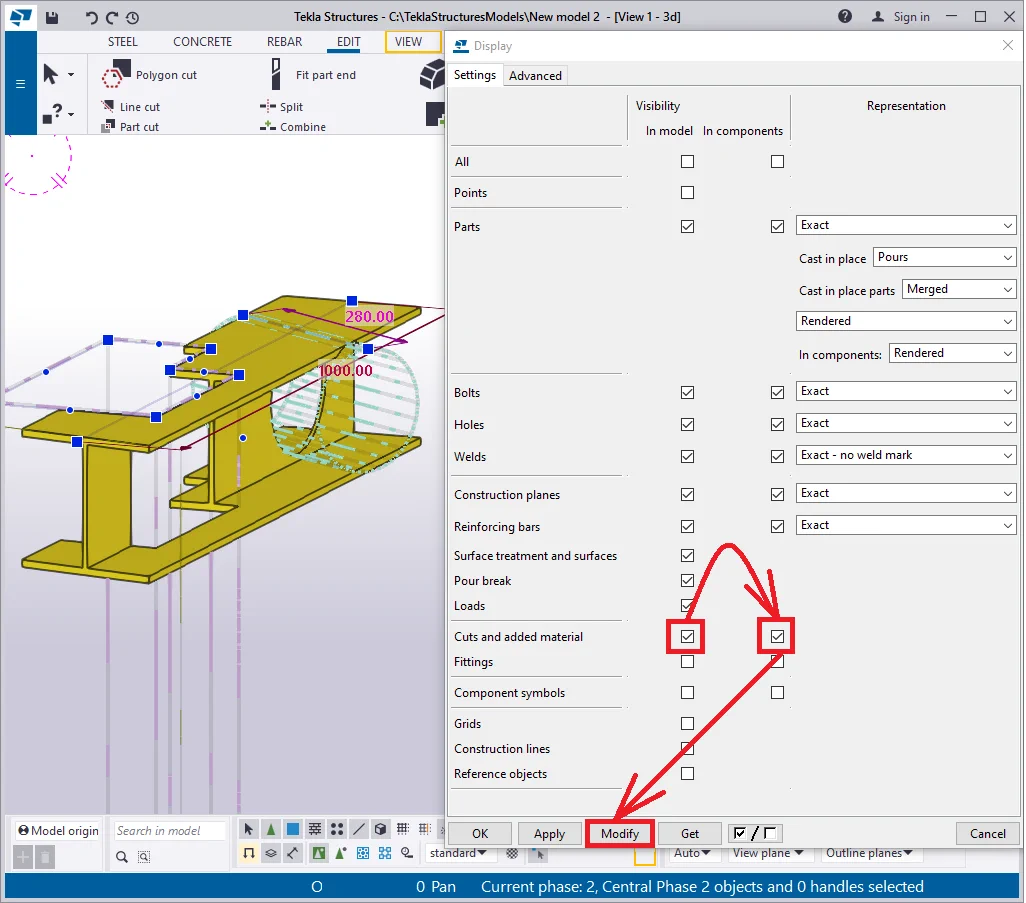
Item 12 -The " Cuts and added material" checkboxes allow displaying/ hiding the added material objects, which are resulted from using the “Polygon cut”, “Line cut”, “Part cut” tools, except for the “Fit part end” tool.

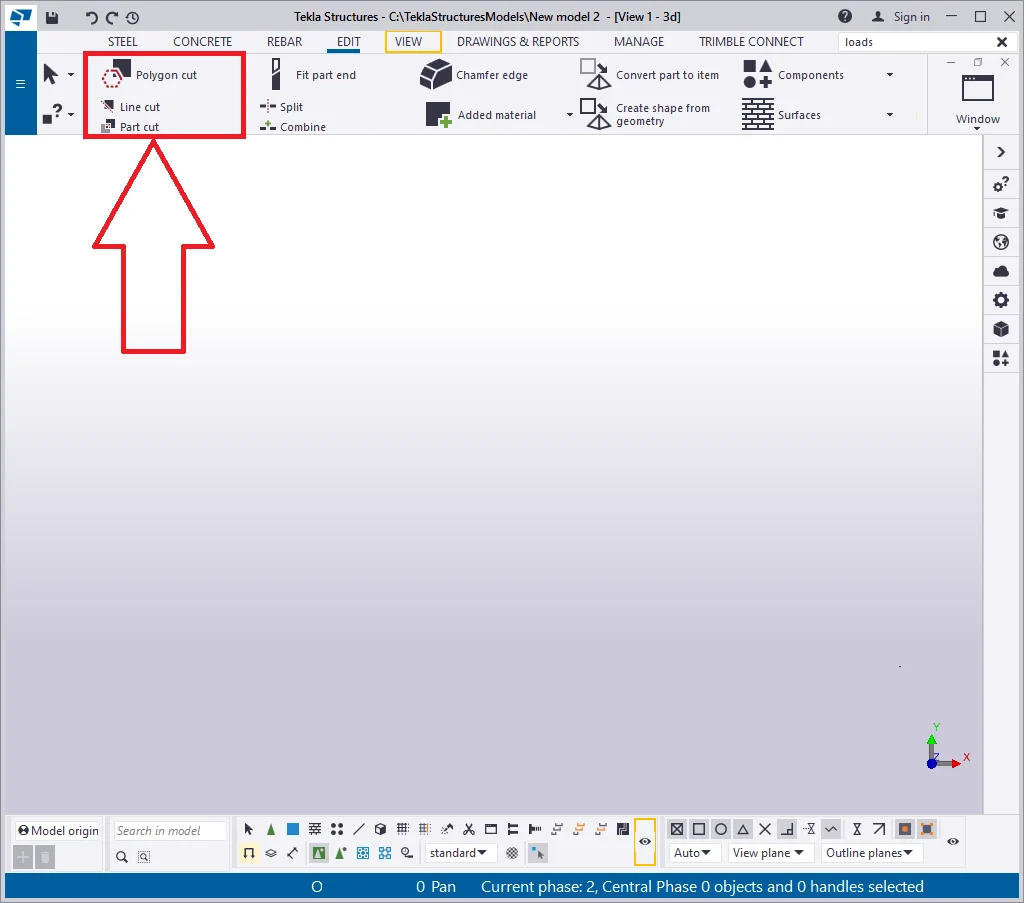
It is important to mention that the output of the tools is always visible,
Let’s create a beam of 1000 mm length and a line cut on it, executed

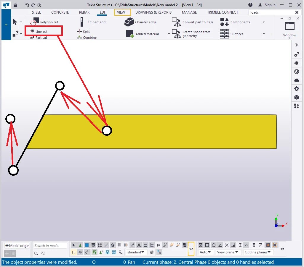
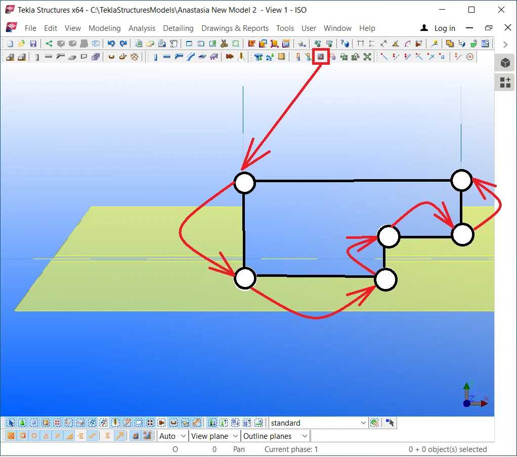
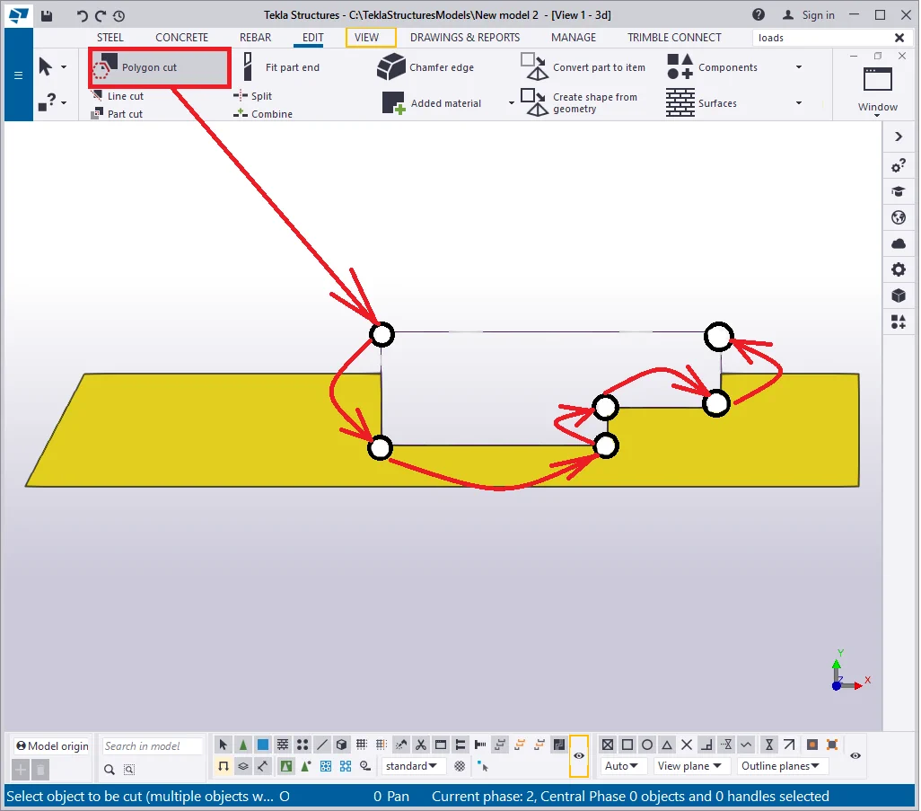
Create a polygon cut as it is shown below:
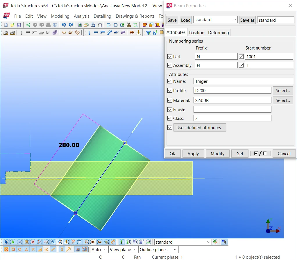
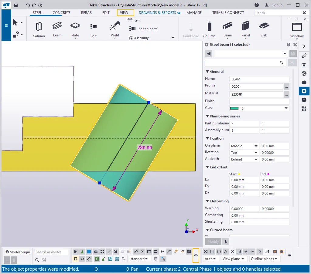
Create a beam with the profile of D200 at an angle to the initial one.
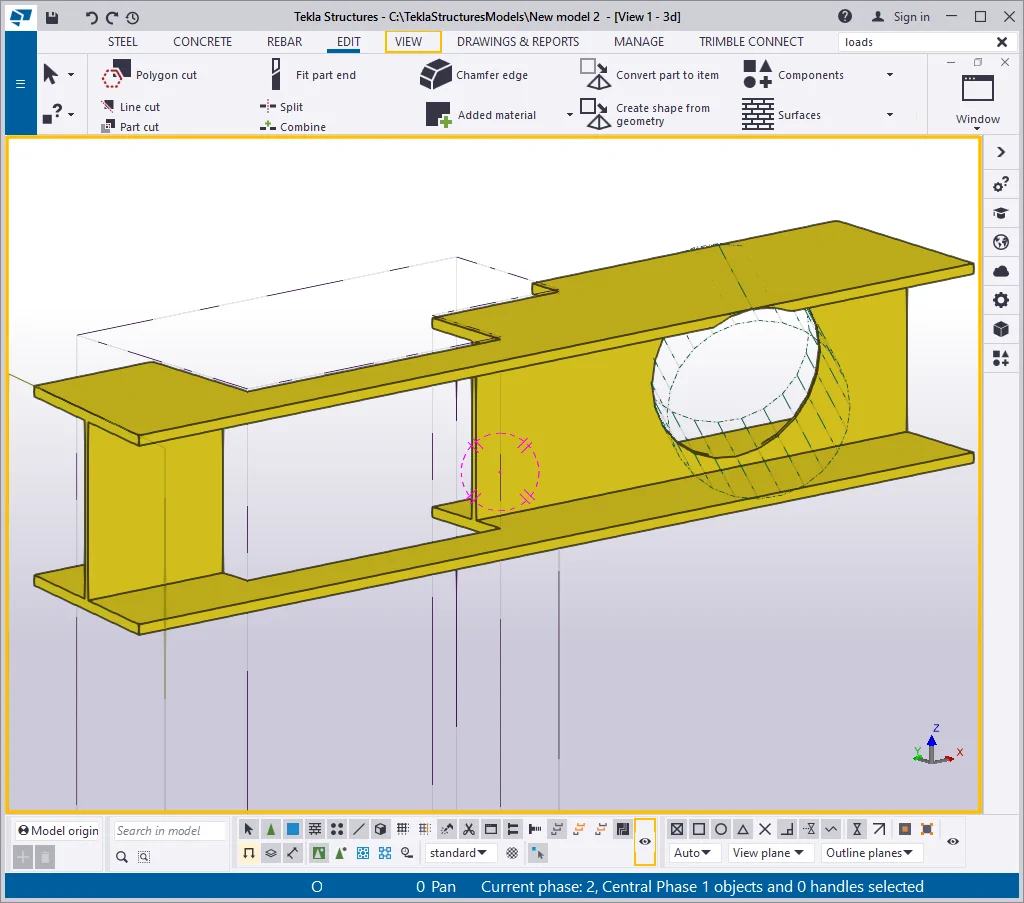
Create a part cut off the initial beam by the oblique beam.
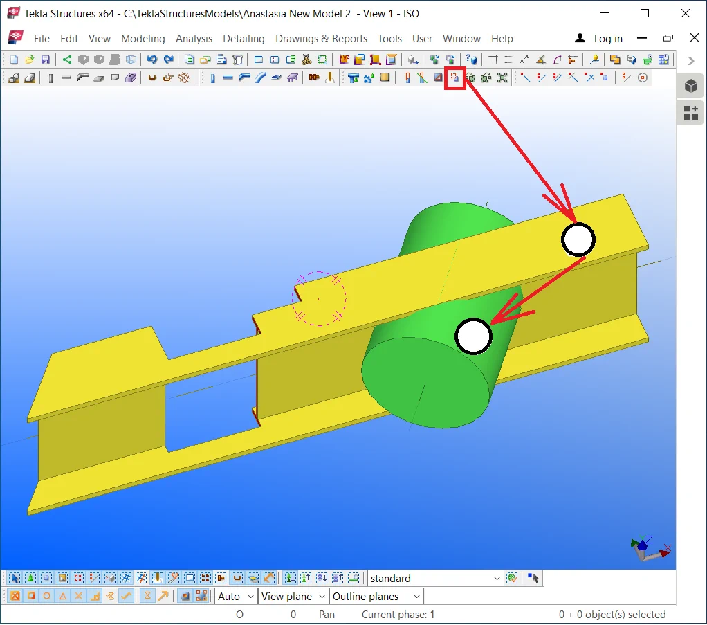
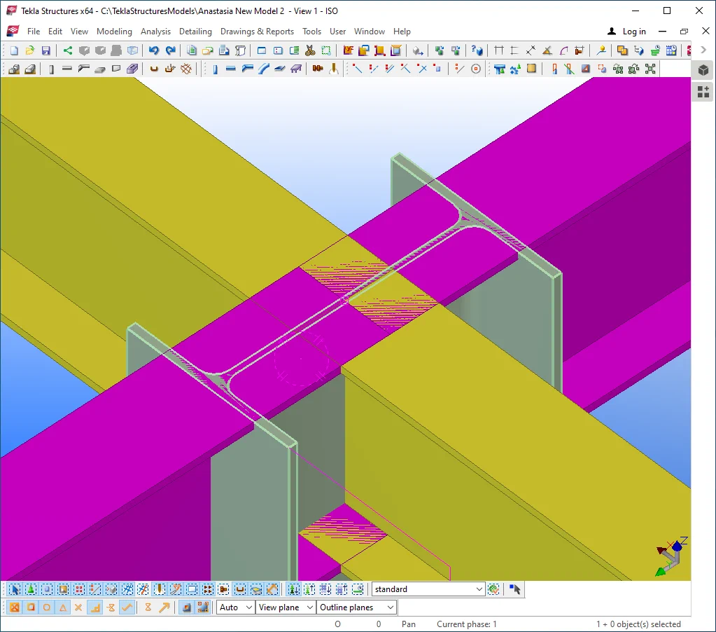
Delete the oblique beam, but leave the added material object. Now we have created all types of added material, which representation can be operated by setting out the “Display” menu.

Redraw the view.
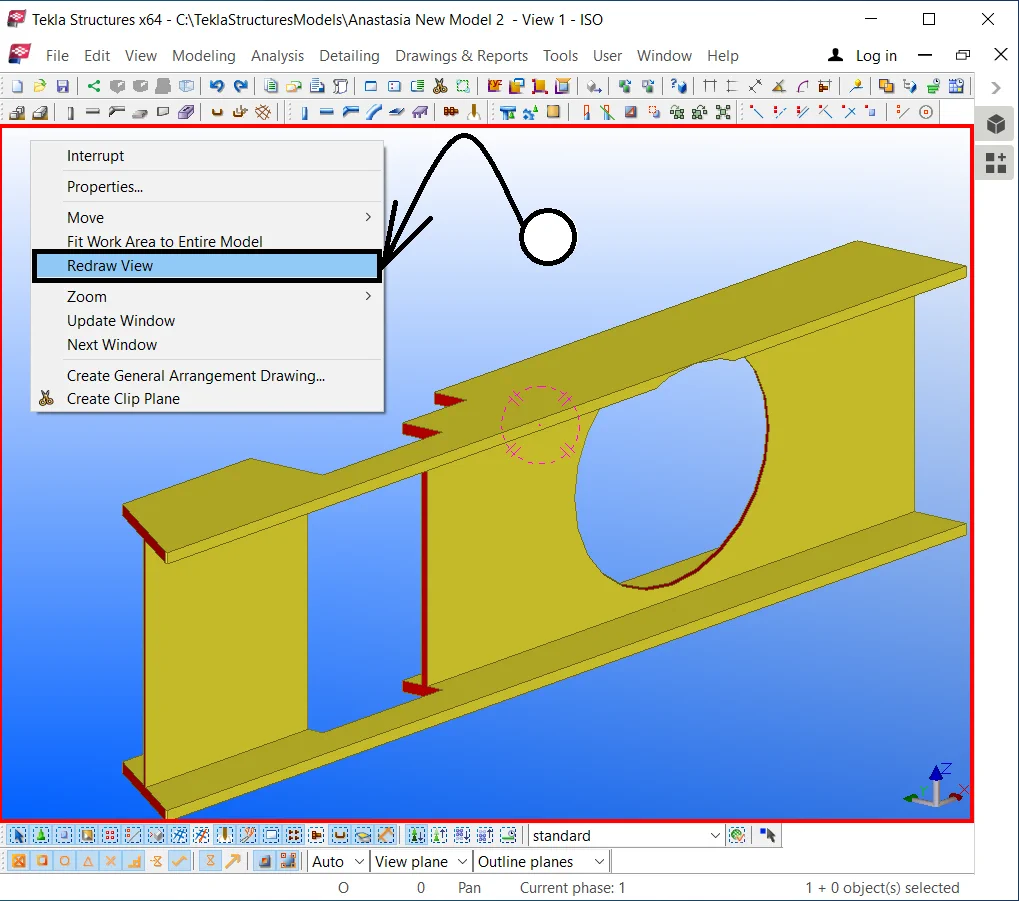
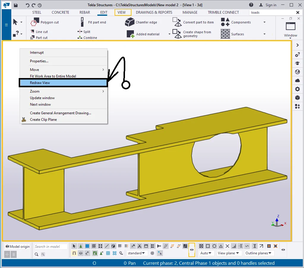
Please note, that only the dash-dotted bodies got hidden (added material bodies), but the cutting line itself and the updated part’s shape remained unchanged. It is not possible to edit the added material geometry as it is not available for selection.
There is a way for displaying any hidden objects without changing the
Let’s try this out by proceeding on the following steps: select the beam, press the “Delete” button and further enable the Ctrl+Z hotkey combination.
Since added material bodies can not subsist without the object which they are shaping out, they have been deleted as well and got drawn back at the backtracking. This method works similarly for welds, bolts, surface treatments, chamfers, reinforcement objects. This is a very handy trick frequently used in practice.
Redraw the view by proceeding to the respective tab in the right-click
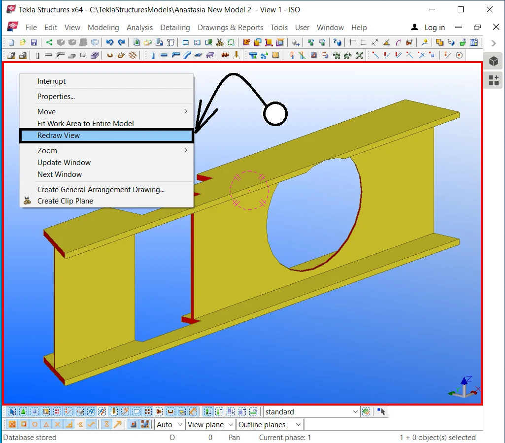
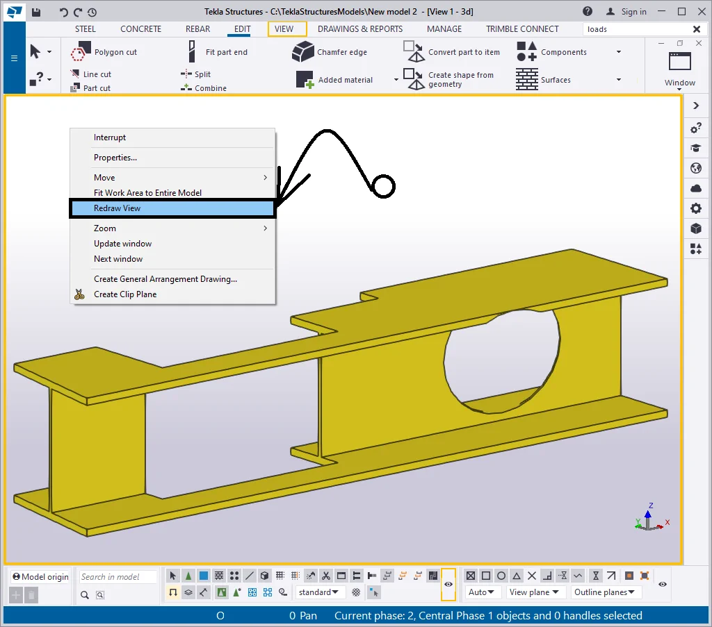
Go to the “View properties” window and enable the “Cuts and added material” checkboxes to display the added material bodies in the model on permanent.
Now, when redrawing the view does not hide away these types of objects.
Item 13 - The " Fittings" checkbox stands for hiding cutting planes, resulted from applying the “Fit part end” tool. Note that the “Line cut” tool outputs are not controlled by the “Fittings” checkbox. The reason for dedicating a separate line for the “Fit part end” tool is that it is one of the most frequent uses for modeling, while the other added material tools are being applied as intended.

The view settings do not affect the properties of the tool, just the visibility of the fitting planes. The part itself is always displayed undercut.
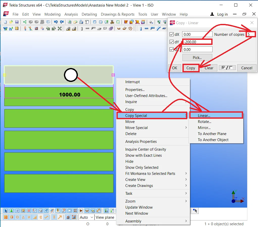
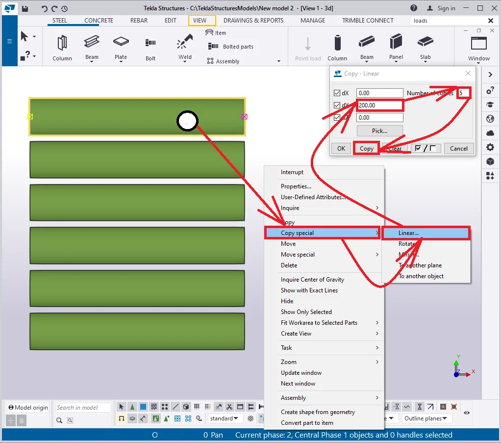
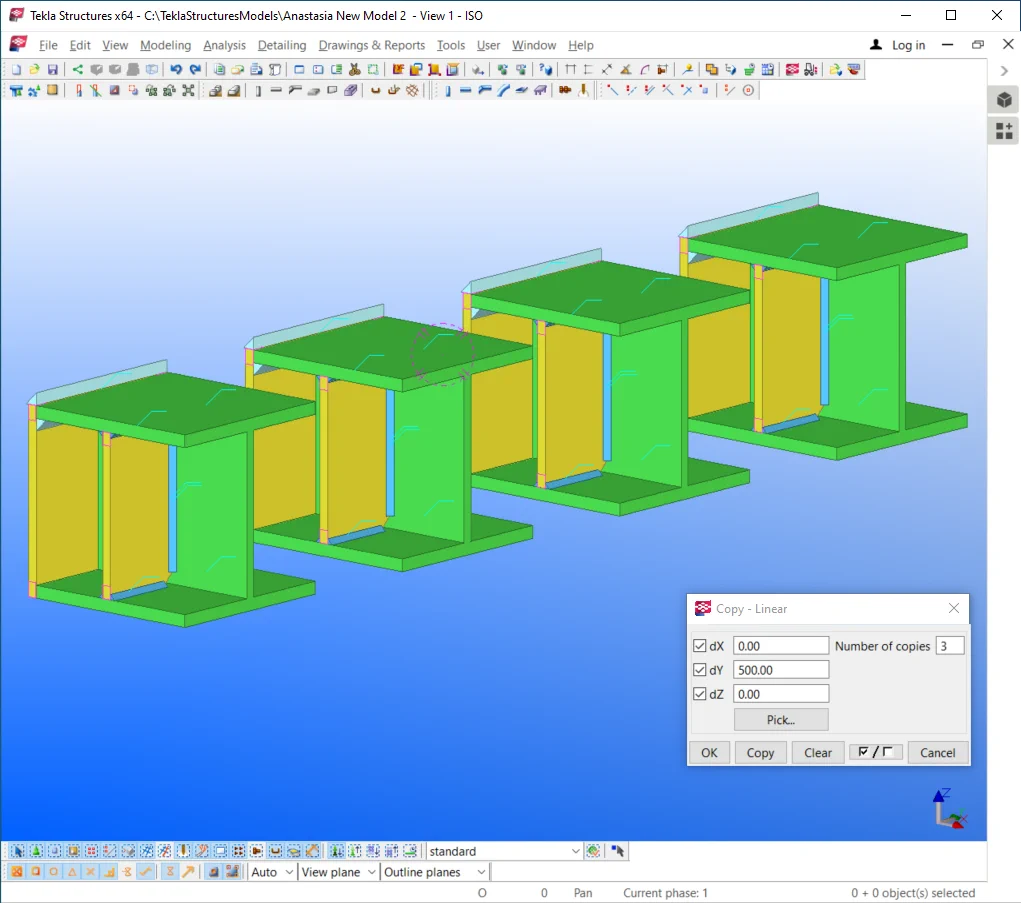
Create a beam of an arbitrary profile, 1000mm in length, at the top view window. Execute “Copy special -Linear” of the beam by Y-axis 5 times equidistantly at 200 mm.
Make sure that the Z-axis is perpendicular to the eye gaze direction.
Apply the “Fit part end” tool simultaneously to all the beams
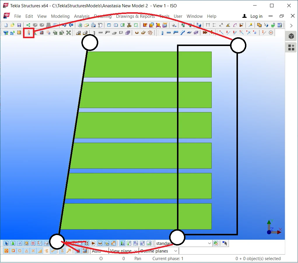

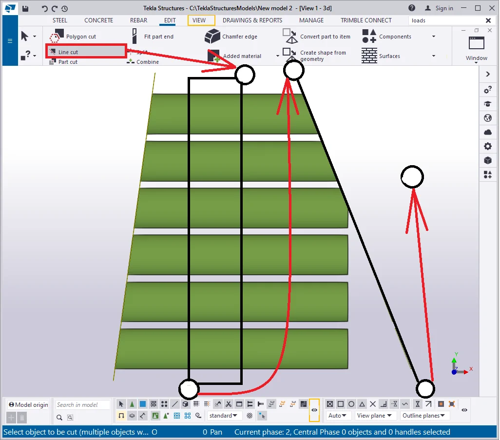
Execute the line cut over the beams at their right side. Keep in mind that the “Line cut” tool requires indicating the cutting side and is not expanding the objects’ lengths.

Rotate the view and make sure that all the fitting and line cut
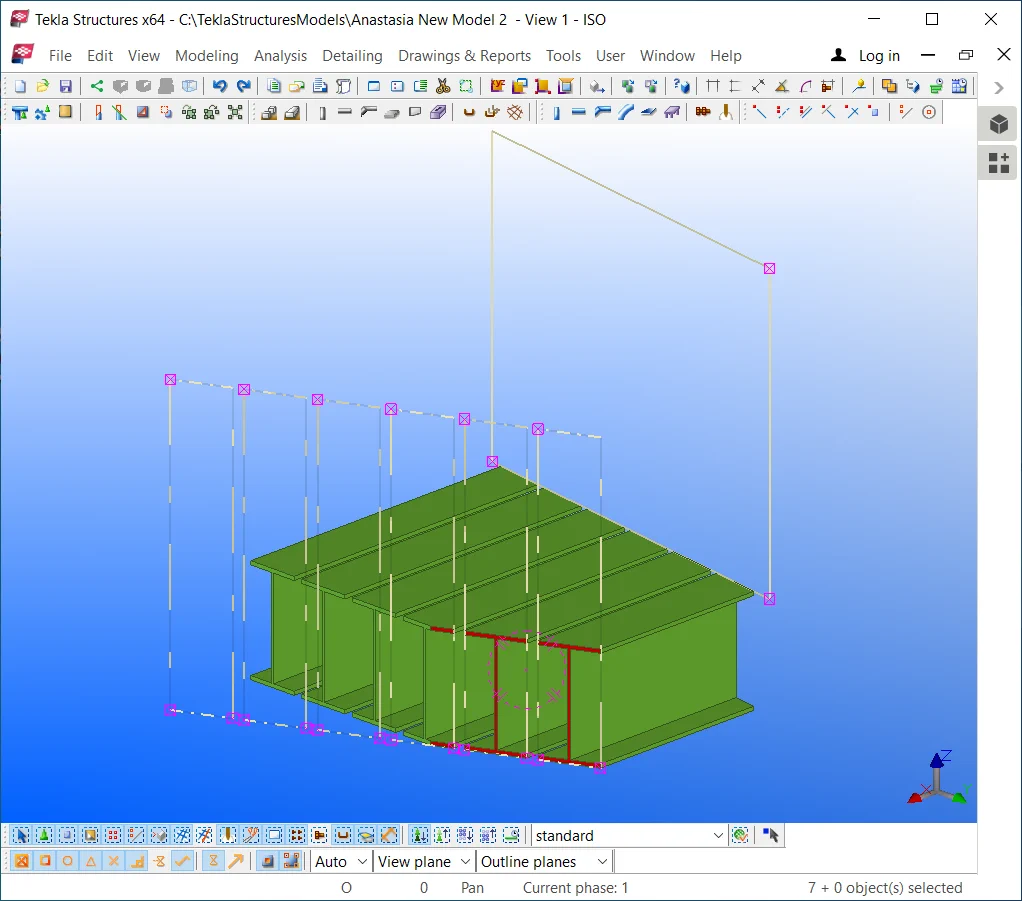
Redraw the view by proceeding to the right-click menu and enabling the
As you can see in the below picture, all the fitting planes disappeared, except for the line cut planes, as visibility of the latter is controlled by the “Cuts and added material” checkbox.

Disable the “Cuts and added material” checkmarks.
Delete one of the beams.


Enable the Ctrl+Z hotkey combination.
The added material body that appeared refers to the deleted and restored
Reenable the checkboxes involved above.


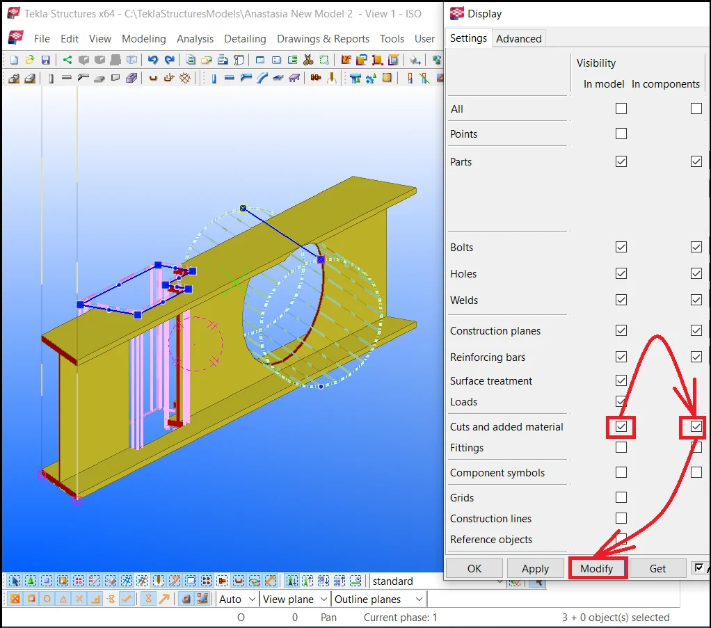
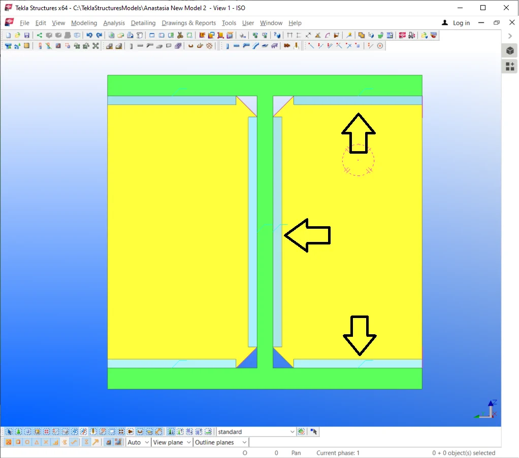
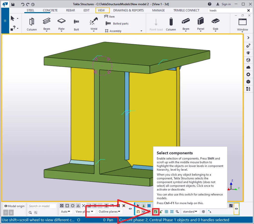
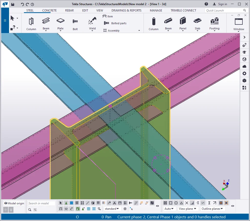
Item 14 - The " Component symbol" checkbox - allows displaying/hiding the clouding indicating the component’s main axis. Clouding looks like a multiaxial arrow. Displaying this symbol defines the way how the connection was created: by using a component or by using parts, not united into a component.
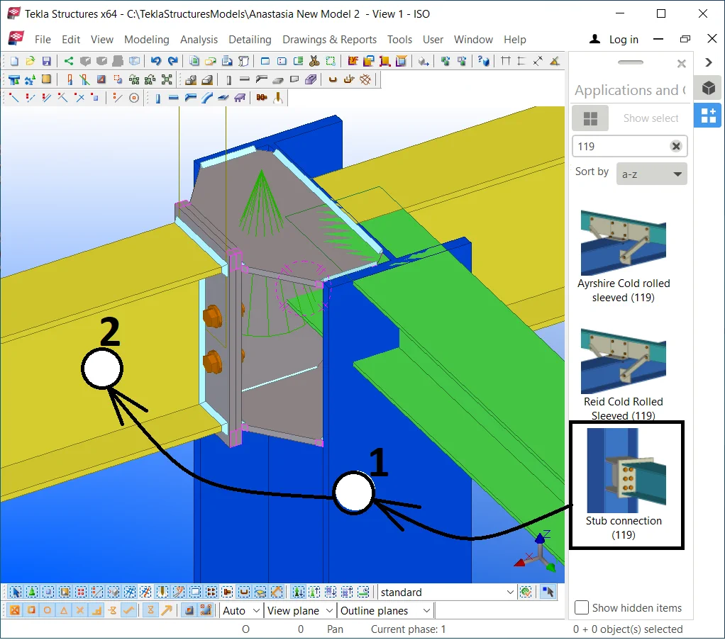
Let's create a connection between a beam and a column. Access the Application and components catalog by enabling the Ctrl+F hotkey combination and find component No 119.
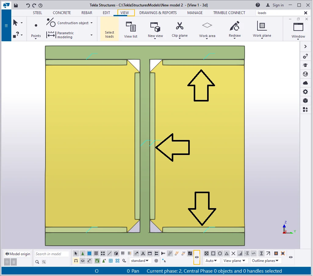
The green lines above the component are the symbol of a component. Redraw
Note that welds, bolts, fittings are displayed at the view, as the respective checkboxes are activated at the “Display” settings menu. Let’s mark up both checkboxes to see the component's symbol. It is important to mention that each component can be composed of several standard components, which are marked by a blue circle on the view. That is why the “Component symbols” check mark refers to two boxes, identifying visibility in the model and components.
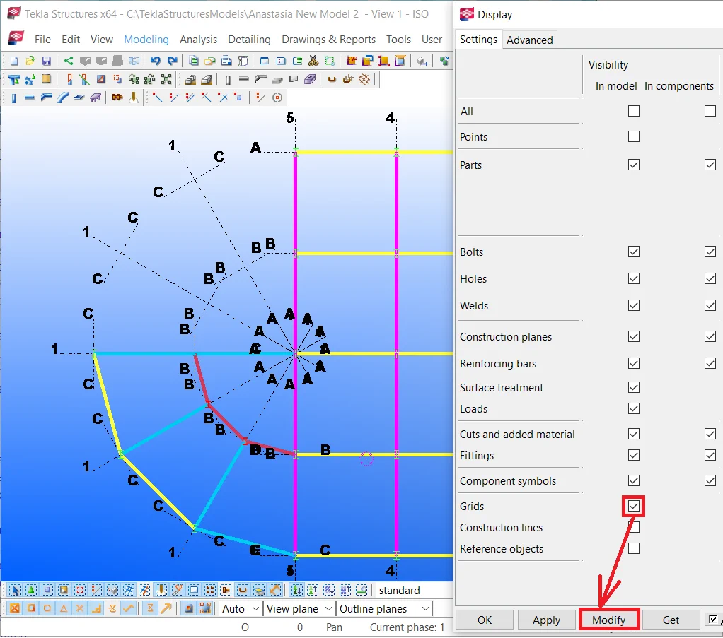
Item 15 - The " Grids" checkbox displays/hides the grids, which might turn into a high exigency case if there are numerous grids in the model. Grids rendering requires sufficient PC resources, as maximizing/minimizing or rotating the view makes software calculating the scale anew.
As we have already created a grid, let’s display it by activating the respective line at the “Display” menu. As grids can not be located inside components, thus there is no checkmark at the column “Visibility in components”.

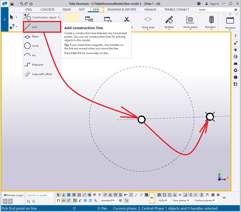
Item 16 - The " Construction lines" checkbox allows displaying construction geometry tools in the model, except for planes and points, these being defined by separate fields at the “Display” menu.
Create several elements, such as a circle and a line.
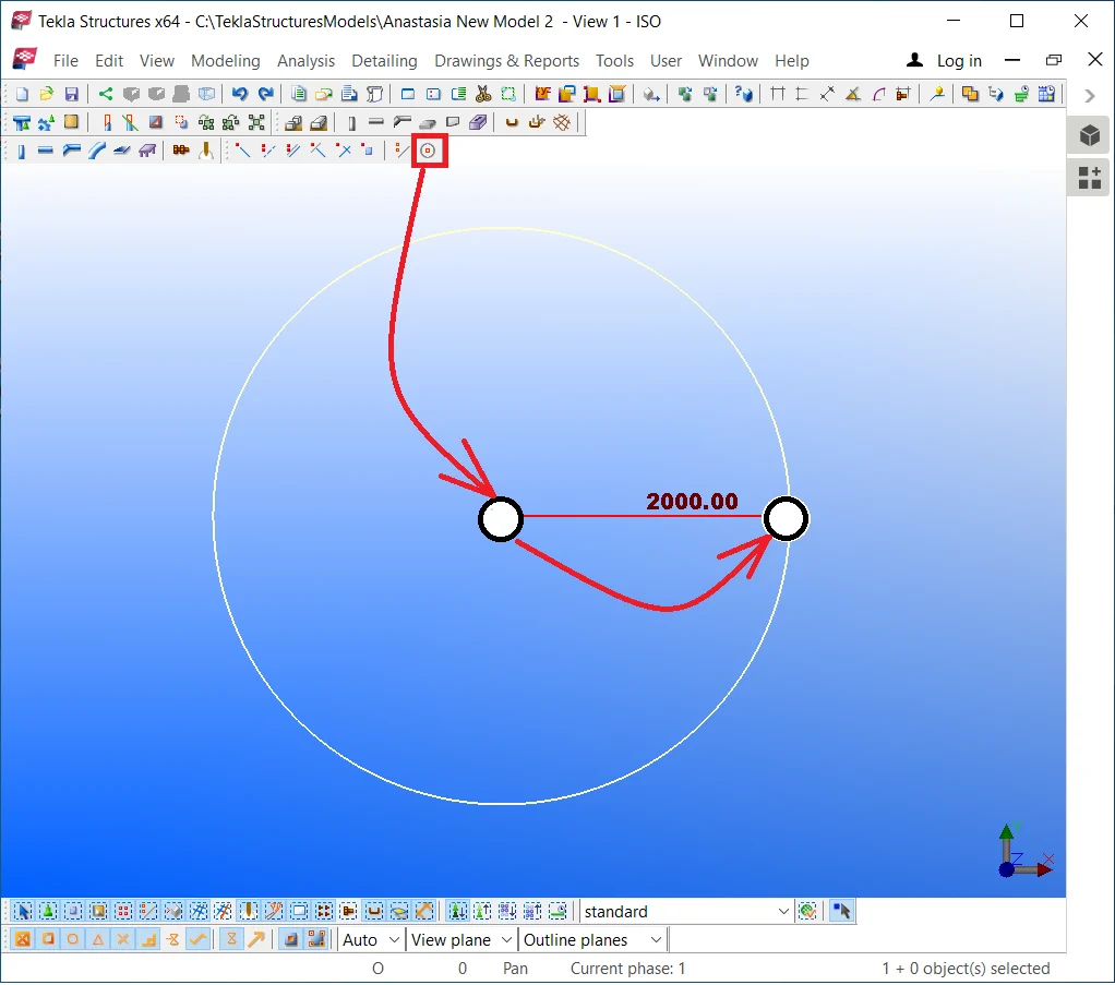

Create a line originating from the circle’s midpoint.
Redraw the view according to the current view settings.
Go to the “Display” menu of the "View Properties" window and set up the respective field for reflecting the construction geometry object permanently.

Item 17 - The " Reference objects" checkbox displays/hides all the reference models, used up in the current project, not depending on their visibility settings.
A reference model is usually represented as a two-dimensional drawing or a 3D model, made up of other software and imported to the Tekla Structures. These models are mostly of Dwg, Dxf, IFC formats.
When importing such models make sure that the view settings allow displaying
|
|
|
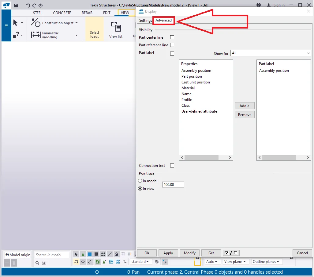
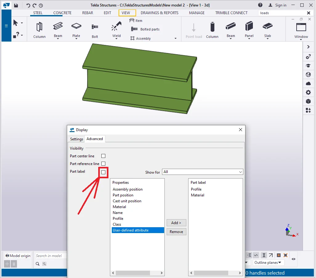
The “Advanced” tab of the “Display” settings window

Create a beam of 300 mm.

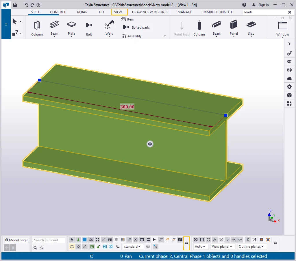
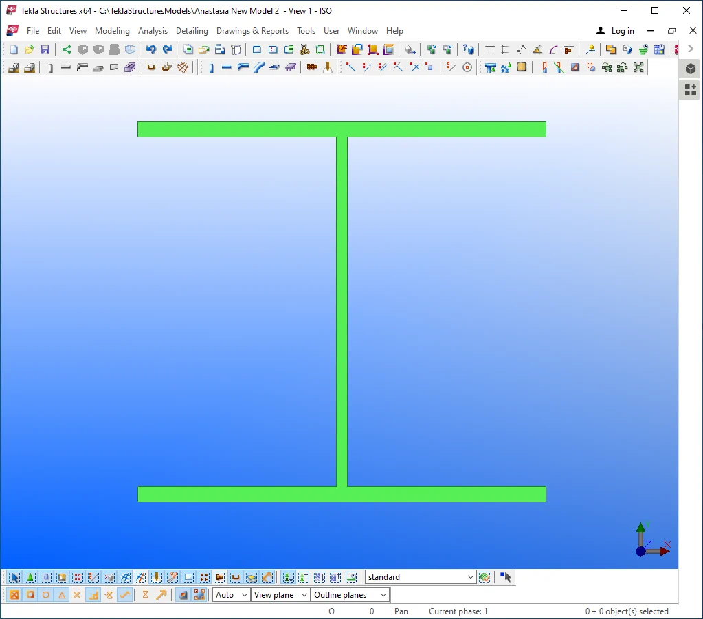
The centerline of a part
Go to the "View Properties" menu / "Display" button / "Advanced" tab and enable the “Part center line” checkbox.
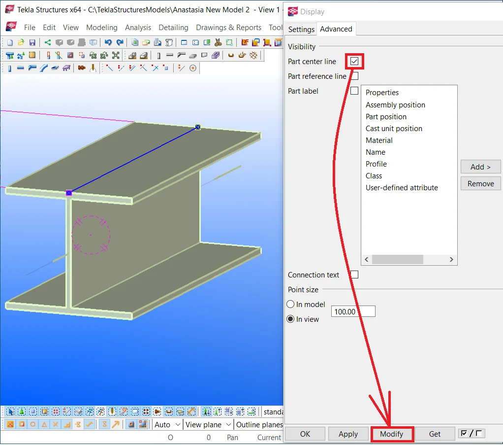
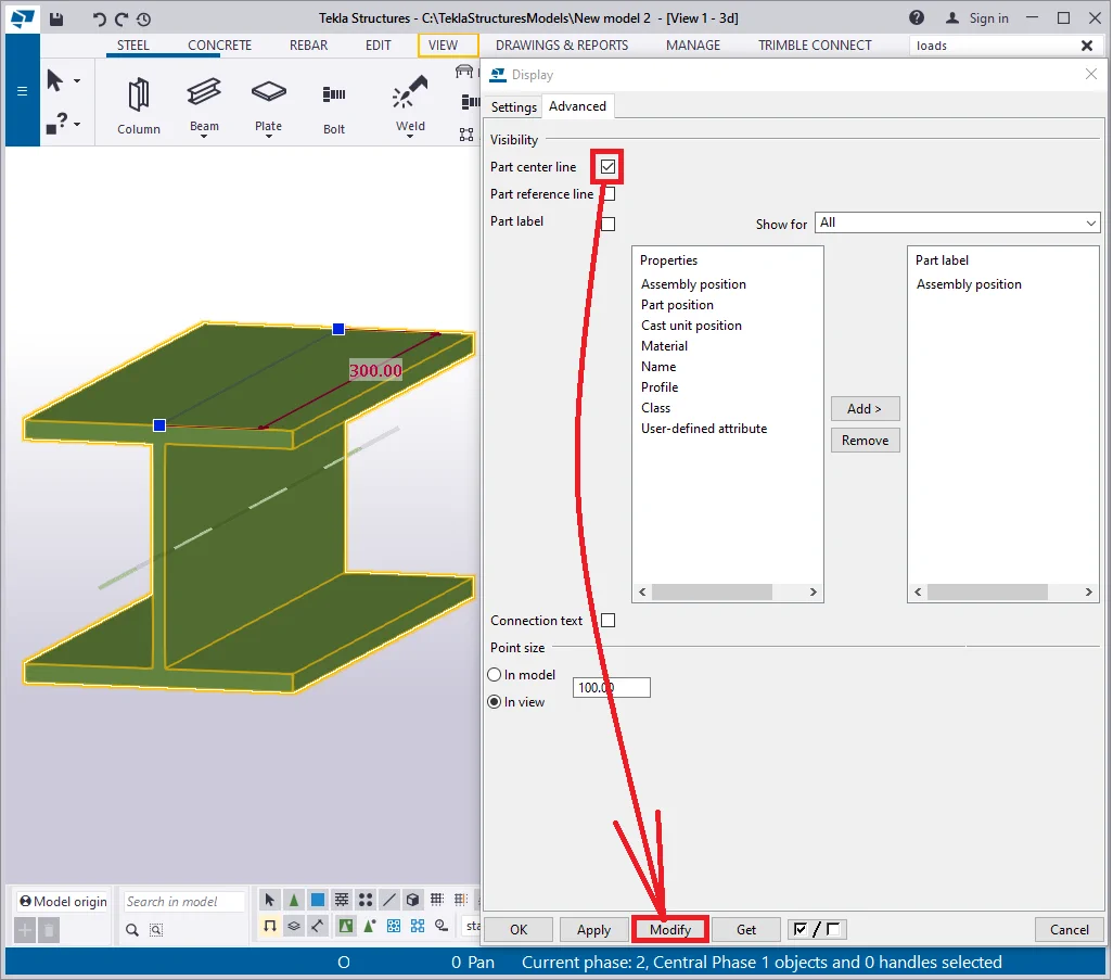
Note that the beam is drawn up by the line passing through the object’s
Part reference line - is the exact line through which the object was drawn up. The profile type itself is of no importance, just the points defining the reference line.
Switch off the part centerline checkmark, and enable the part reference
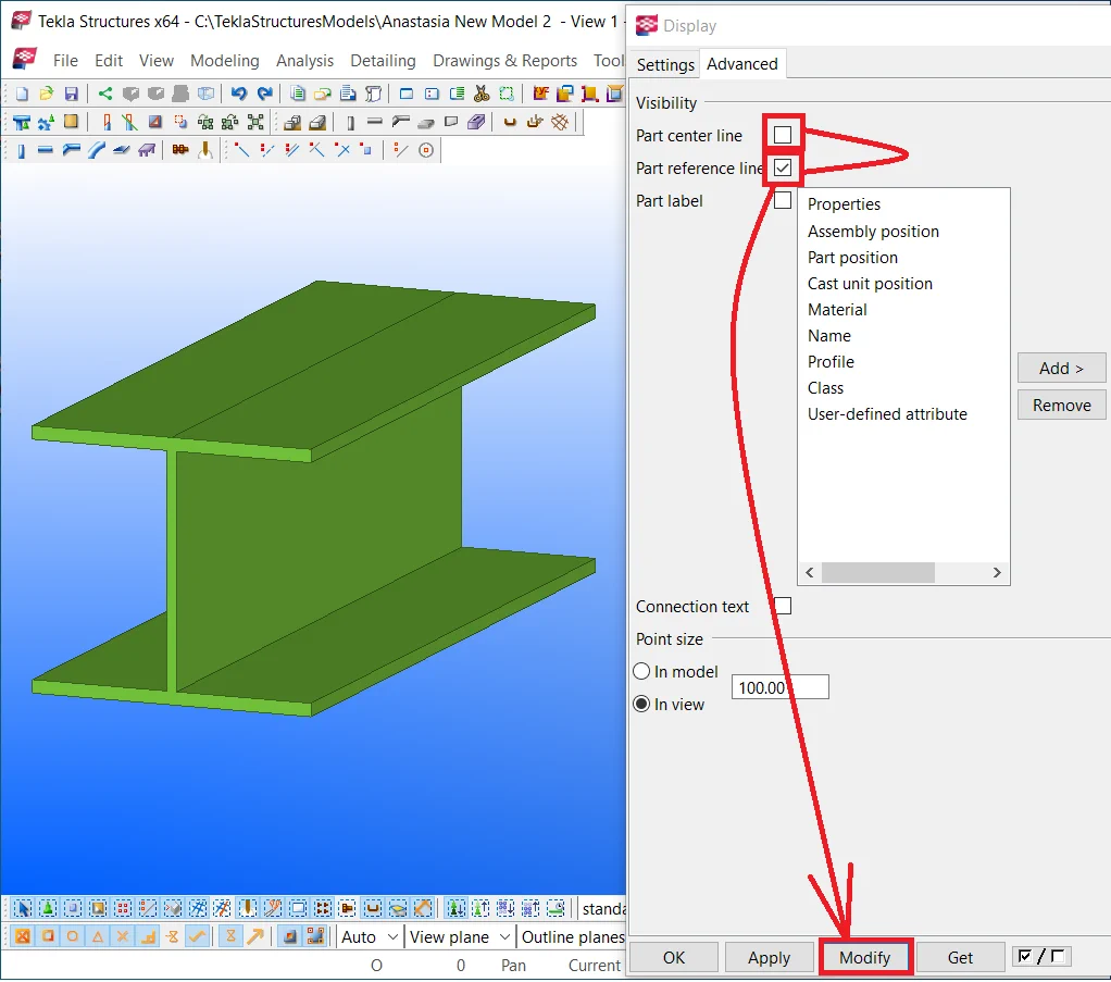
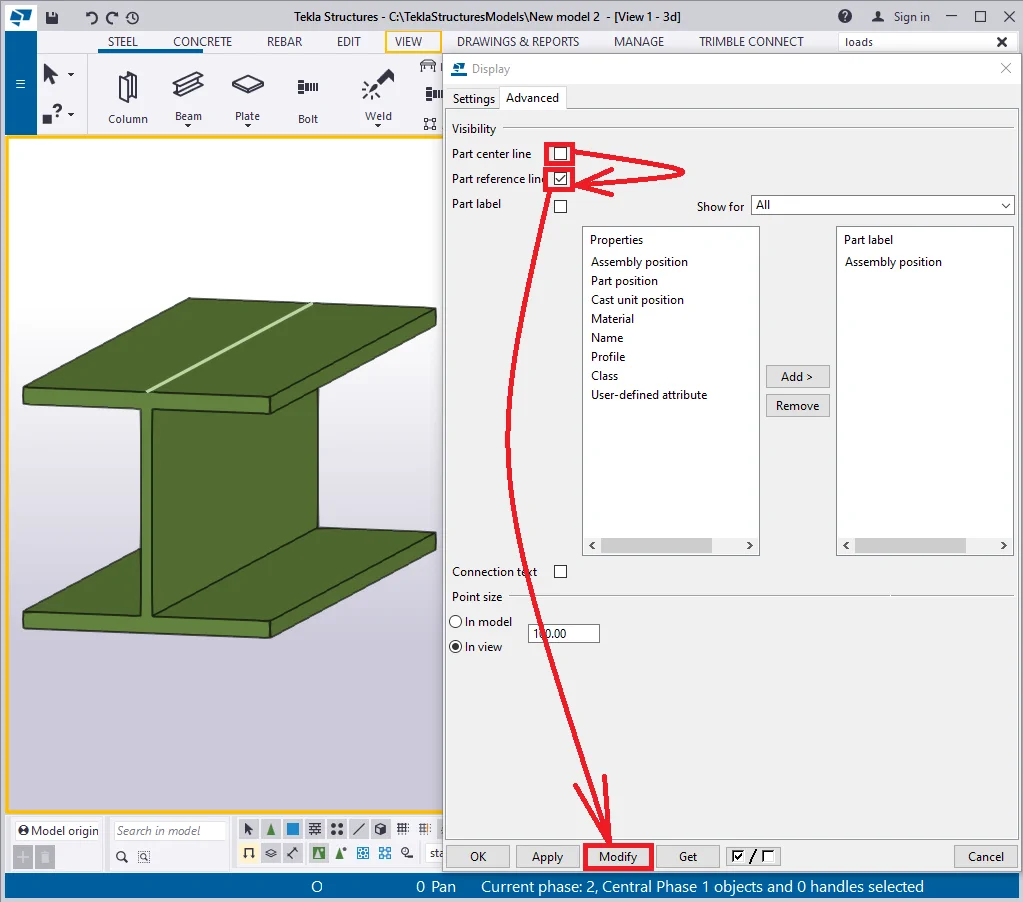
The reference line is marked with yellow. Thus it is possible to indicate
Remove the respective checkmark.
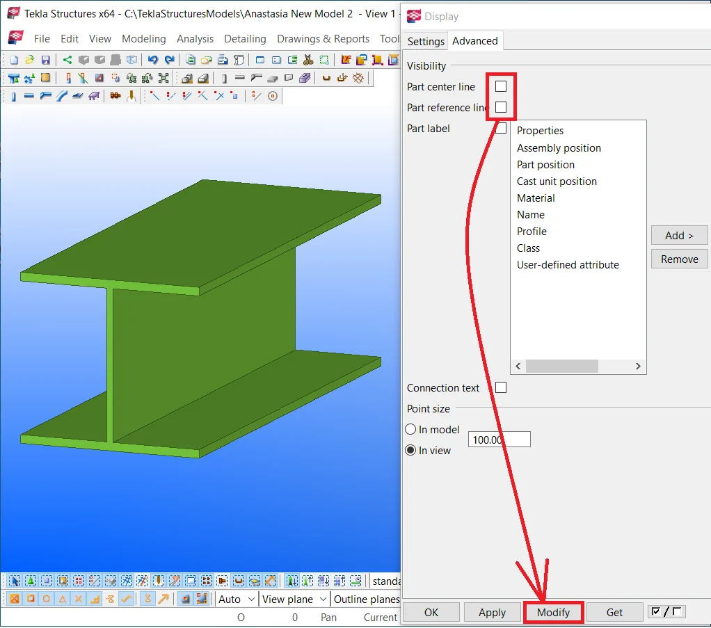
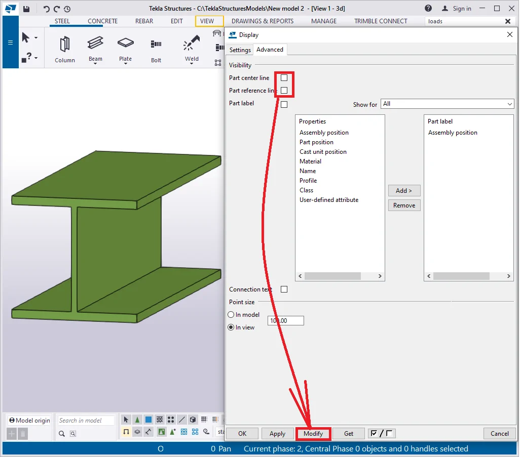
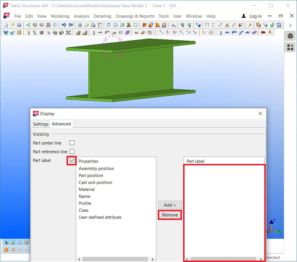
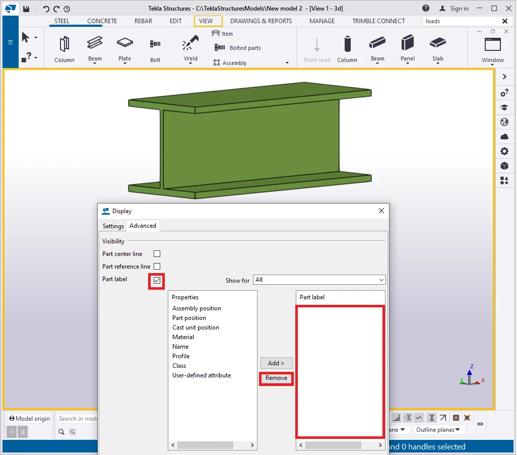
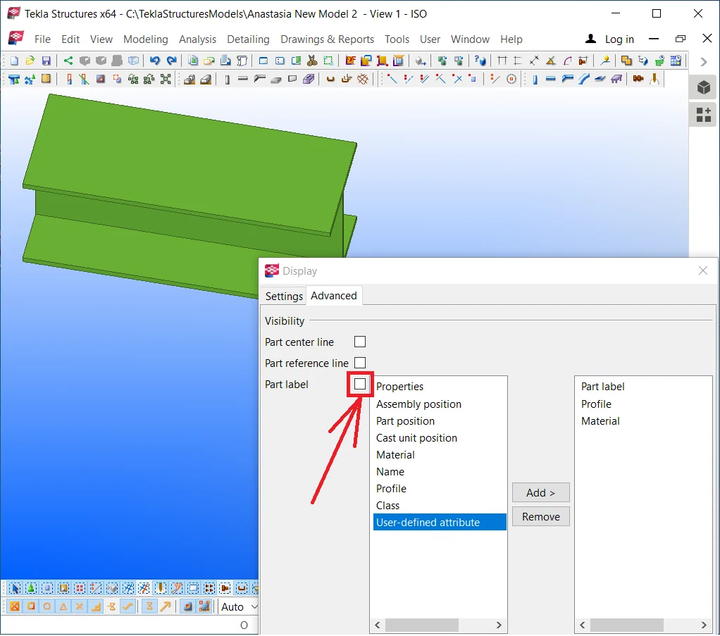
The "Part label" checkbox allows creating the part’s body directly in 3D labels, such as profile, material, etc.
Enable the part label checkbox, make sure that the label box is empty,
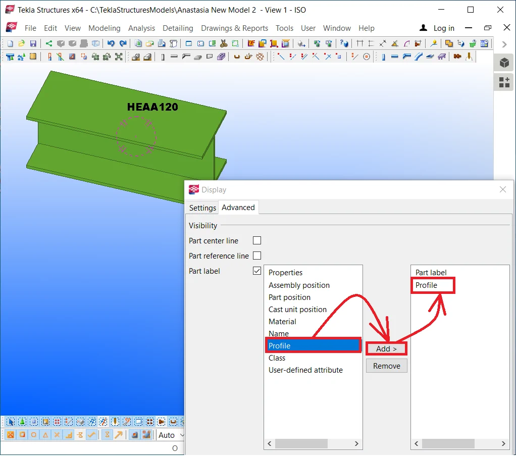

Select from the labels’ list the option: “Profile”, press at the “Add” button, and subsequently at the “Modify” button.
Do not forget to select the required view before the above, otherwise,
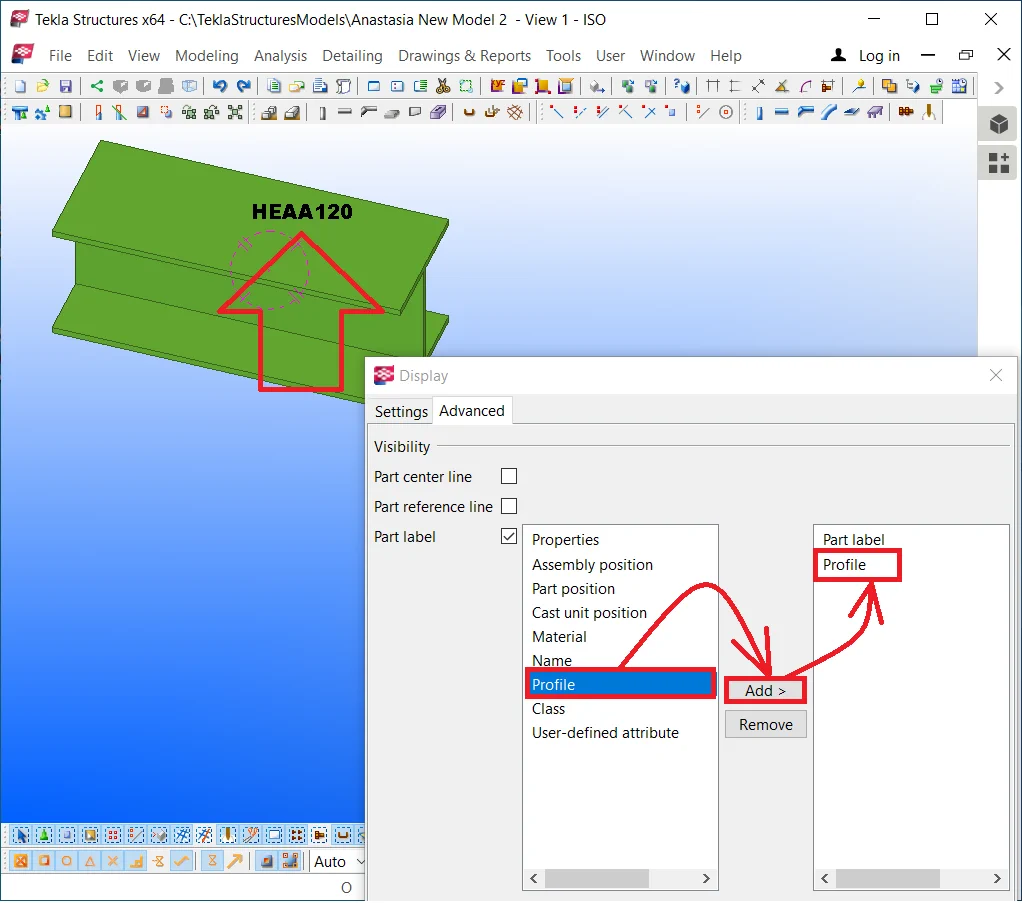
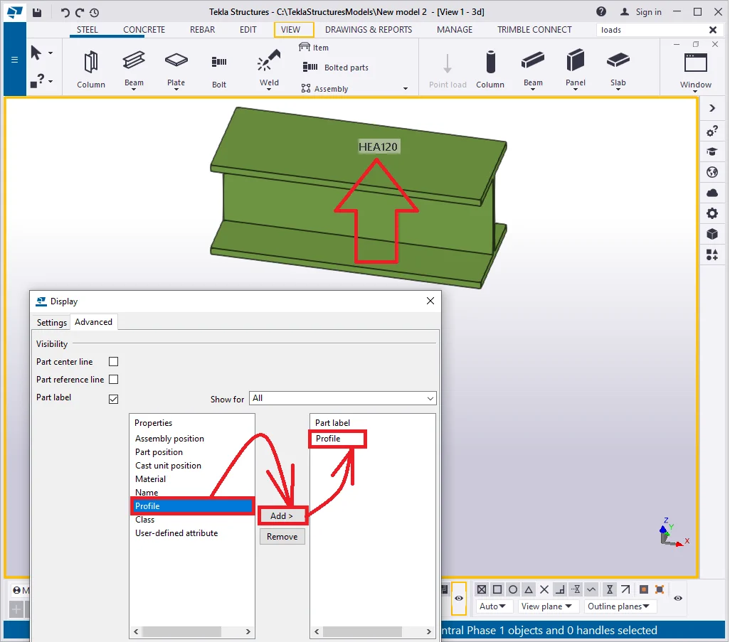
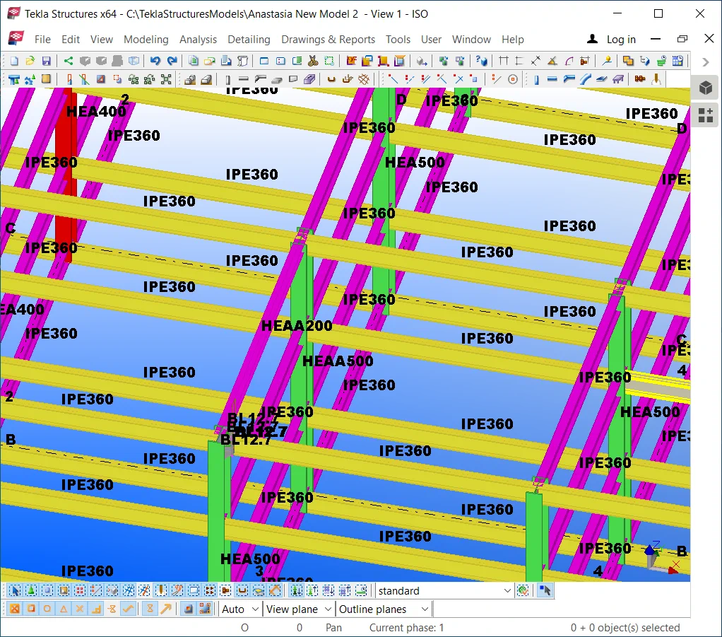
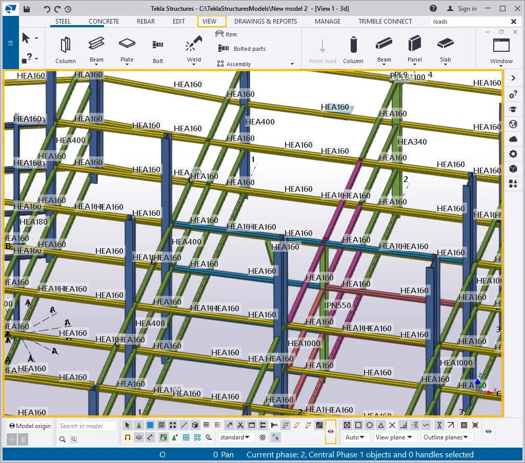
Now each detail is labeled with its profile type. Due to the fact, there are plenty of objects in a model, using this label is an exceptional case.
Now add to the selected labels list the “Material” option
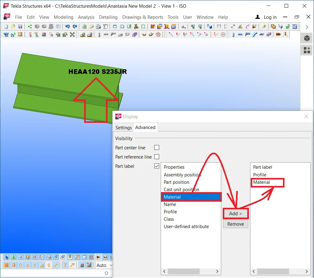
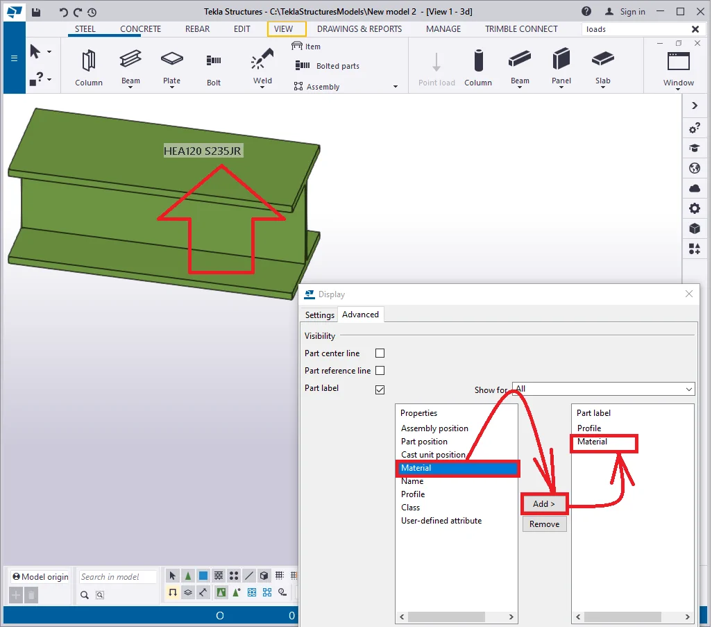
Now the beam is marked with two spaced labels.
The algorithm for adding the other label variables is similar to the one described above. There is only one special label as “User-defined attribute”, which marks up at the beam body the attributes defined by the user. For example, the connection type to be applied to the beam starting point, and its endpoint. Thus labeling beams by their type allows using various connection components to various beams.
Click on the “User-defined attributes” line and press the
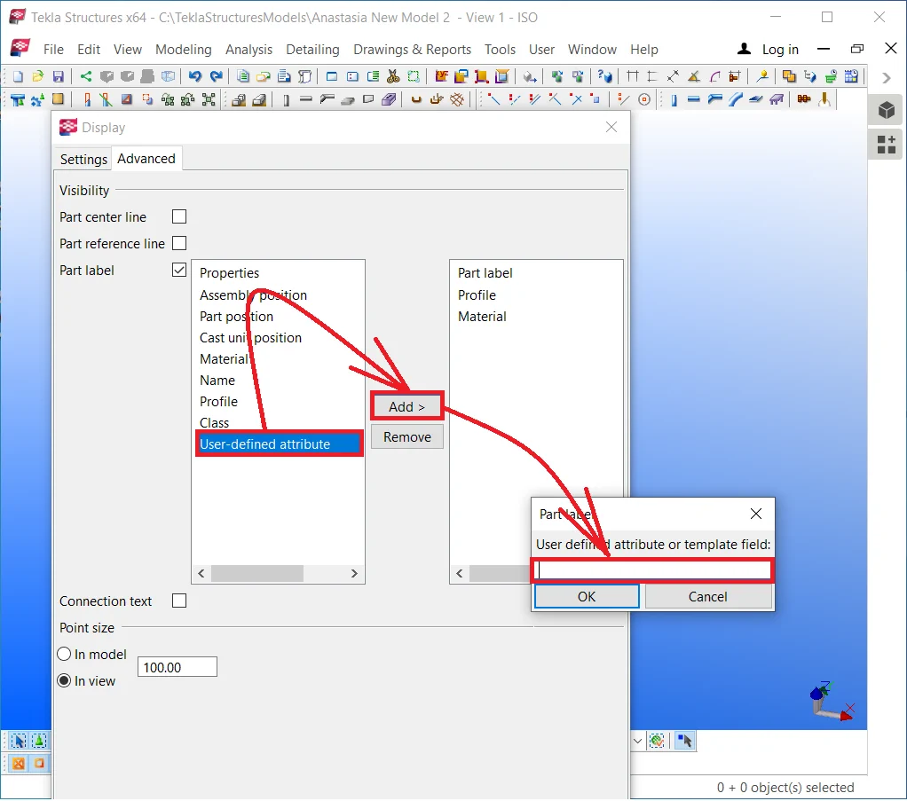
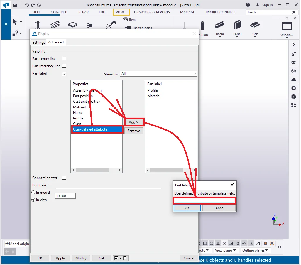
The TS automatically opens the “Part label” dialog window where the new attribute title is to be written in. We will not exercise creating a new attribute, as this is the topic of the on-coming chapters. Now let’s fix it up, that there is a possibility to reflect necessary information at the part body directly in the 3D model.
Remove the checkmark at the “Part label“ line.
The "Connections text" checkmark keeps
Let’s create a connection between a beam and a column, thus go to the "Applications and components" catalog and find component No 119.

All the labels in 3D have disappeared. Now enable the "Connection
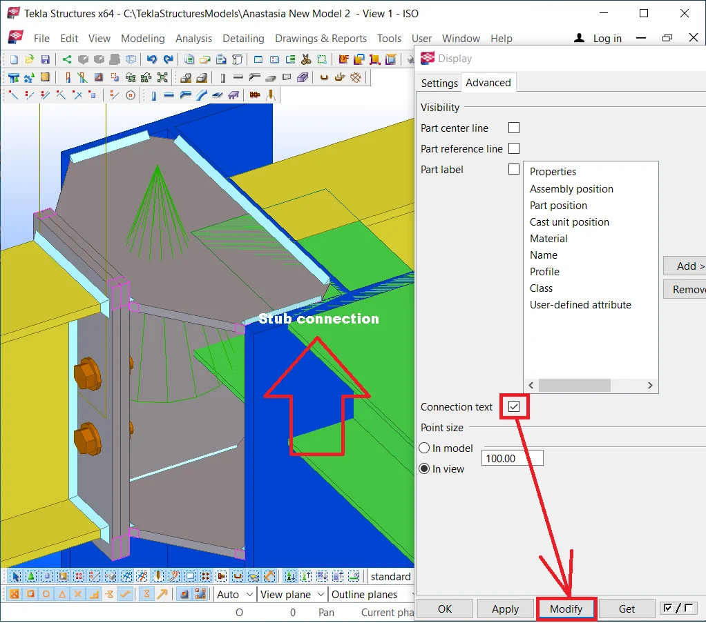
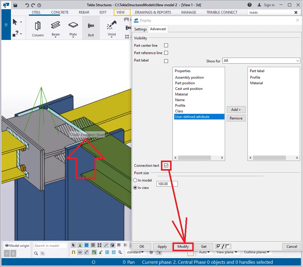
In the above picture, you can see that the connection has got its title string right above. Due to the fact, there are plenty of objects in a model, it is an exceptional case using this label.
Switch off the checkmark.
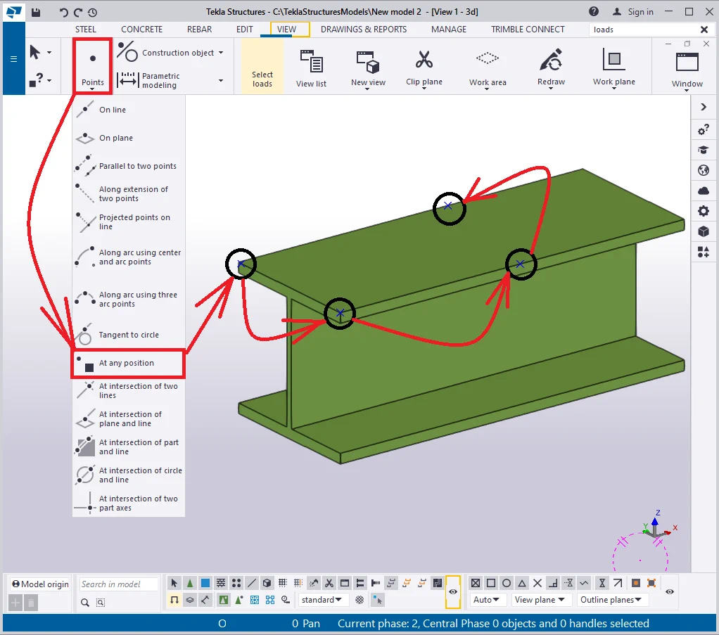
The "Point size" checkmark
Create a beam of 300 mm length of an arbitrary profile. By using the construction geometry tool, randomly create several points. Refer to the picture below:
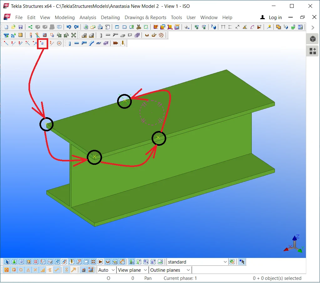
In the “Display” window, write in the scale value of 1000,
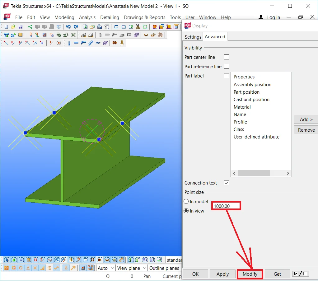
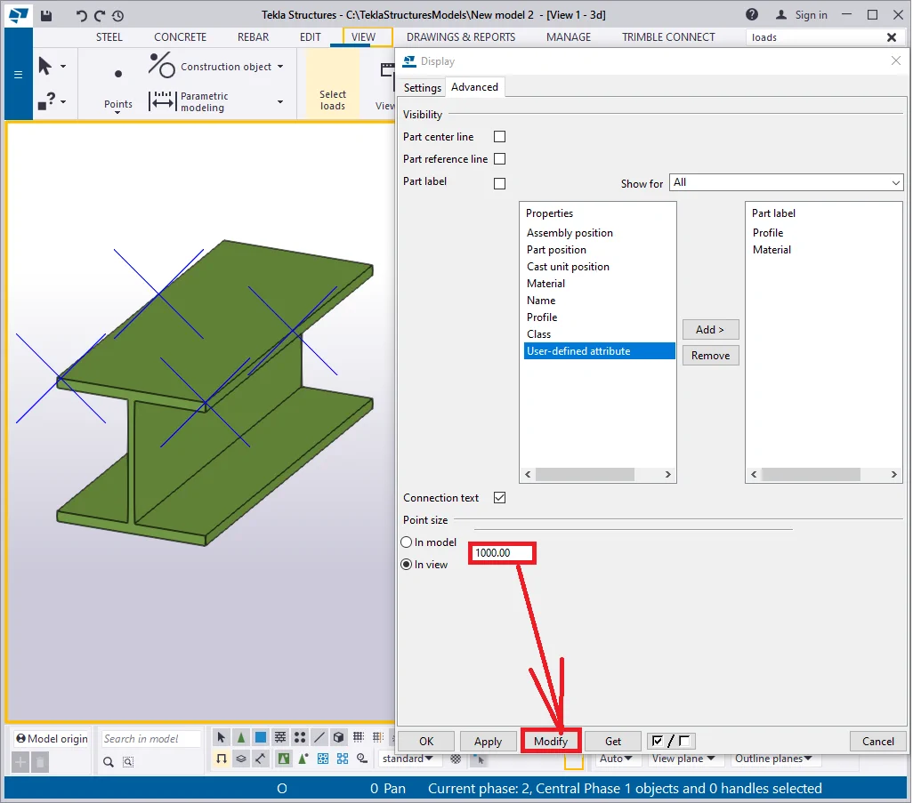
The dimensions of the points changed. When approaching the cursor
Now try out switching the checkmark position to the “In model” and modify the scale value to 200. Do not forget to press the “Modify” button.
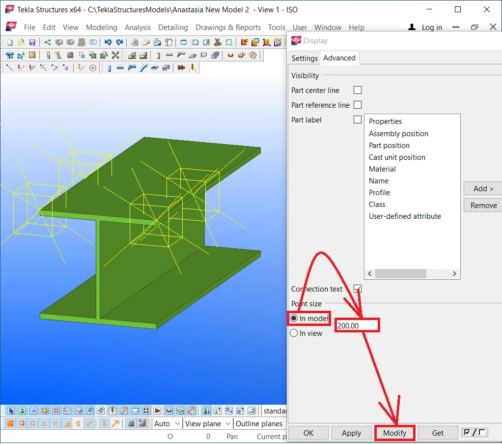

Restore the settings to the initial ones.
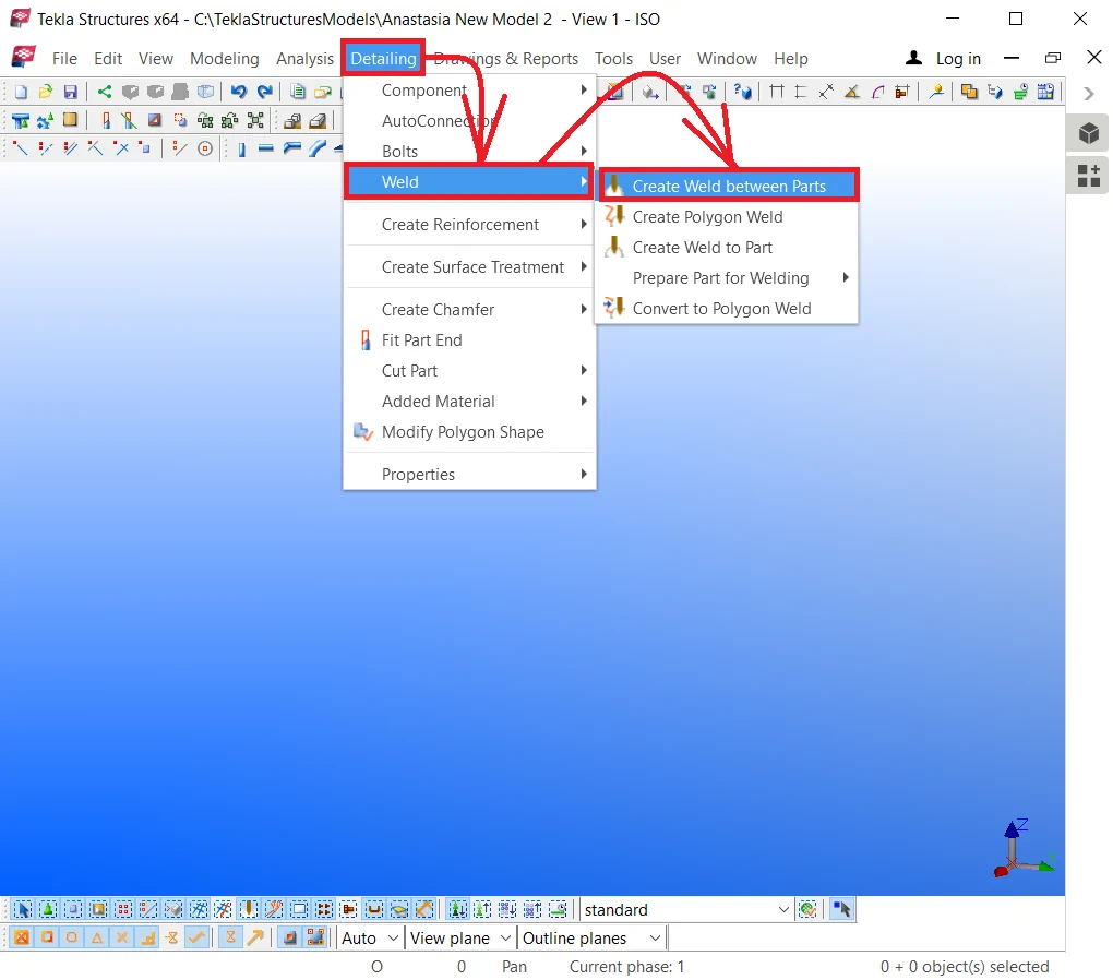
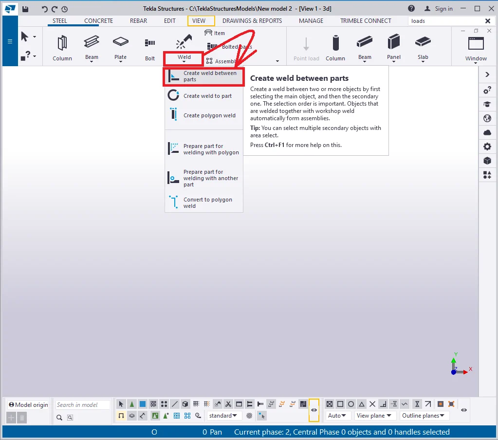
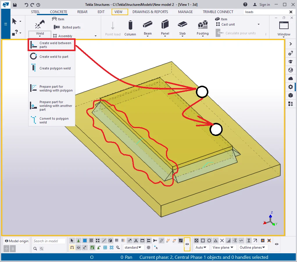
Welding is one of the most important modeling tools, aimed to connect various parts into an assembly. Also, the weld tool can be applied for preparing a part for welding. All the weld tools are located at the “Weld” menu tab. Let’s examine all the tools options available.
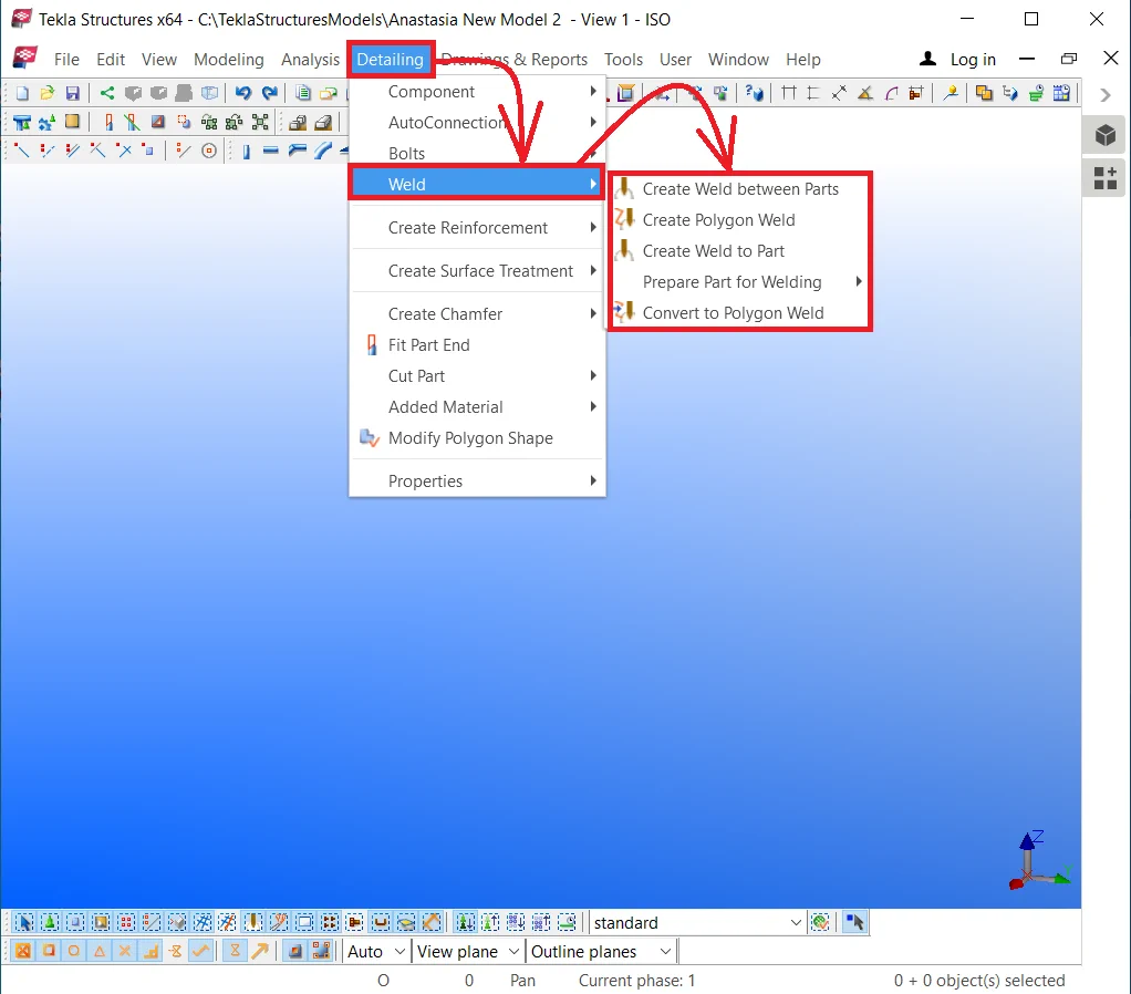
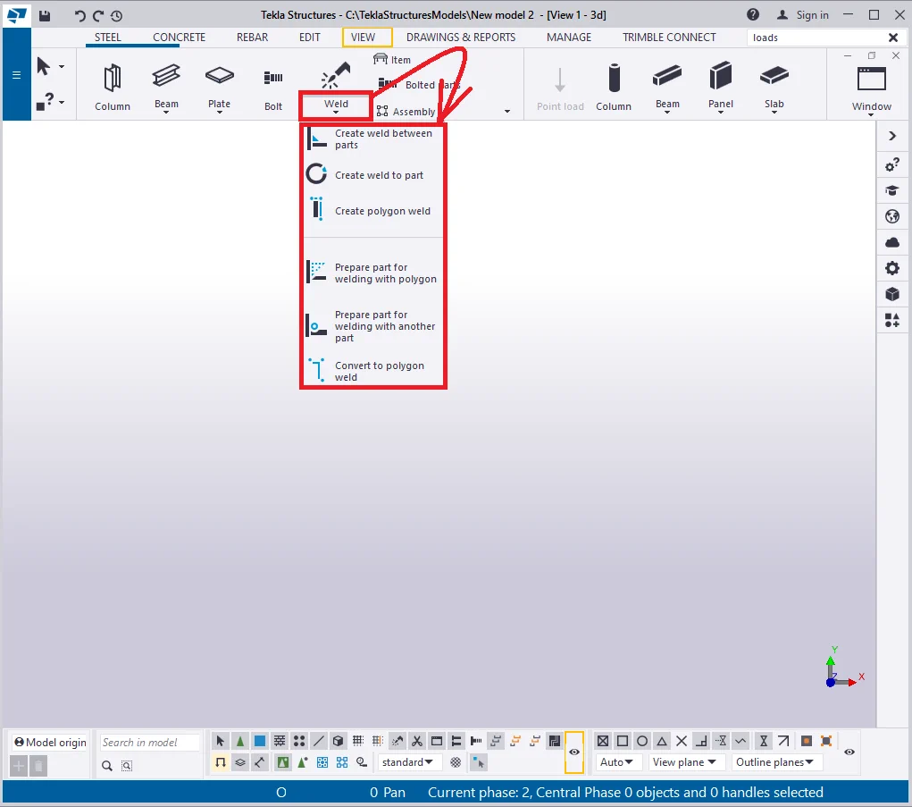
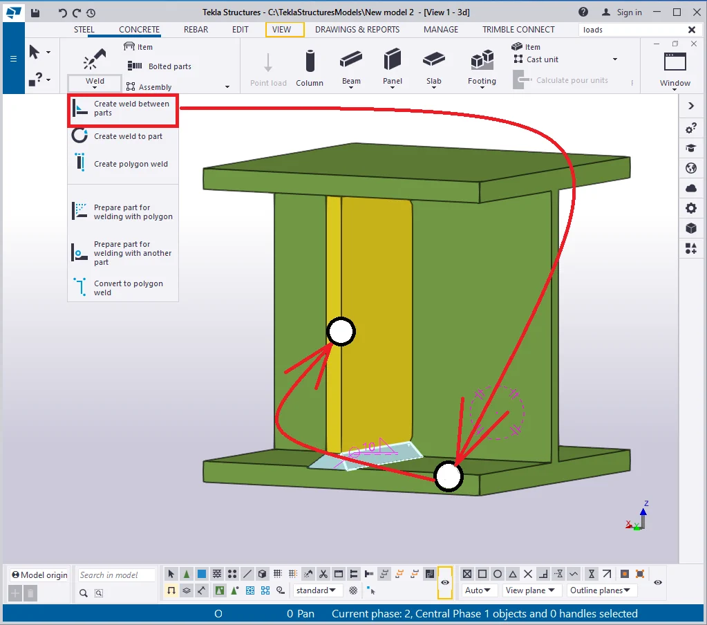
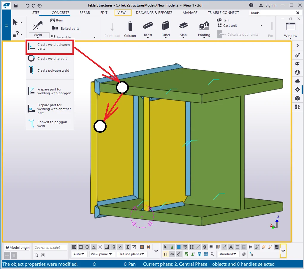
The "Create weld between parts" tool is the most frequently applied weld seam type, which does not require specifying the exact weld line location.
When welding parts together the TS automatically creates a new assembly unit and an assembly drawing. Thus, consider the weld as the tool which joins parts (objects) into an assembly.
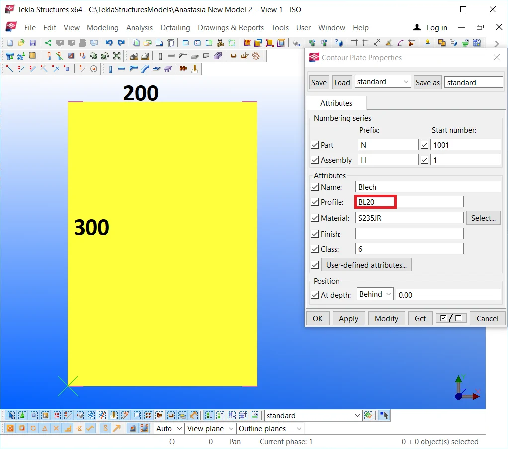
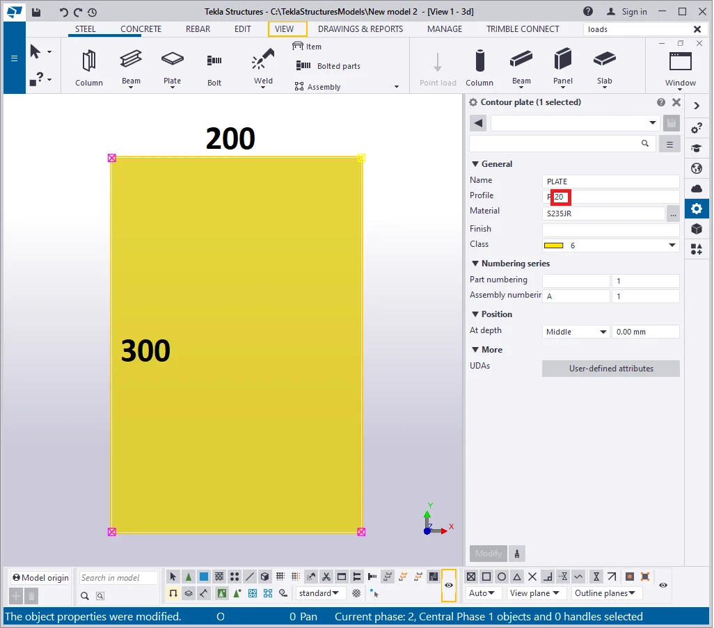
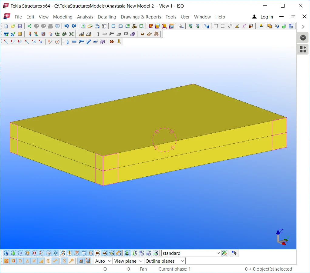
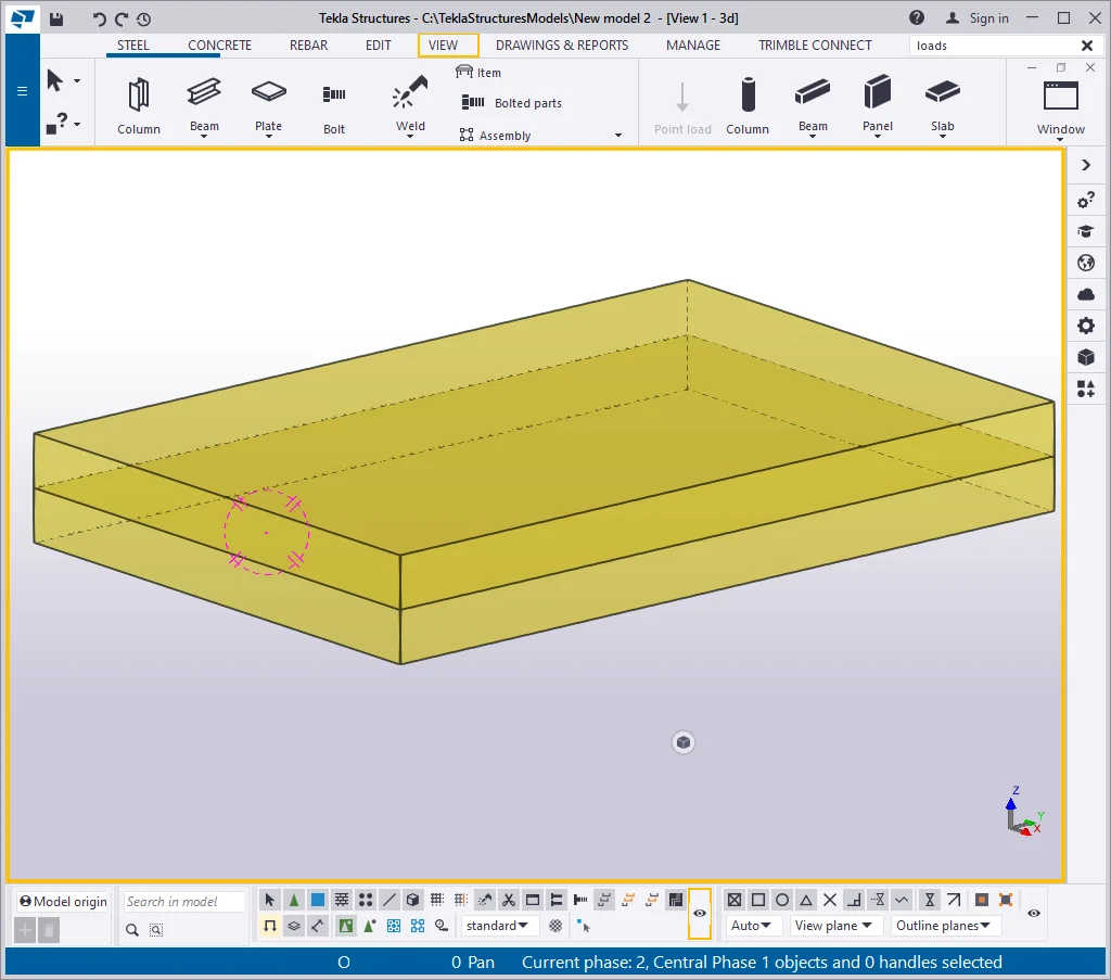
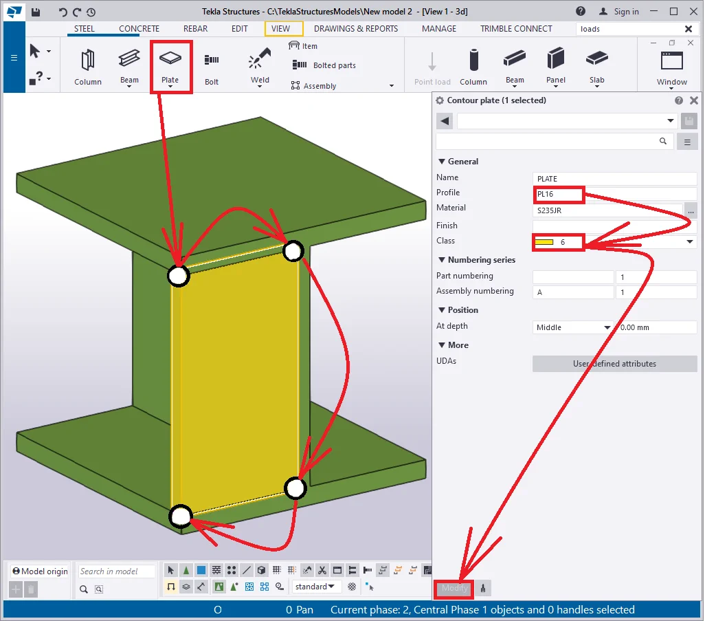
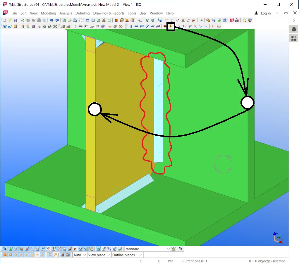
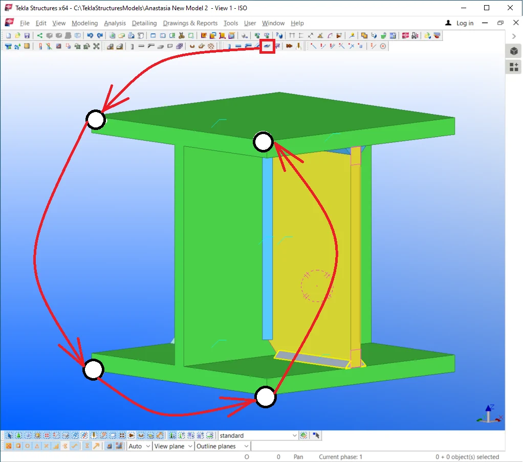
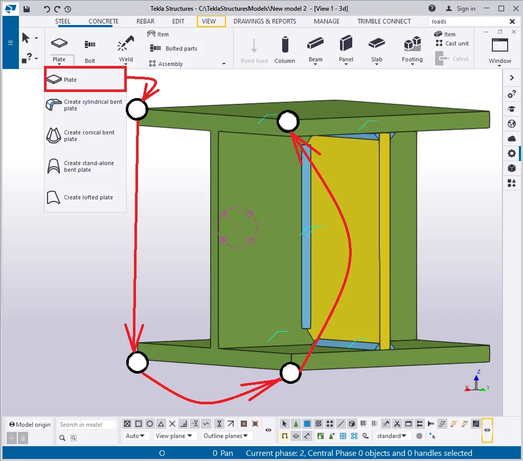
Before exploring the features of the tool, create a steel plate with dimensions
Copy the plate vertically similarly to the below:
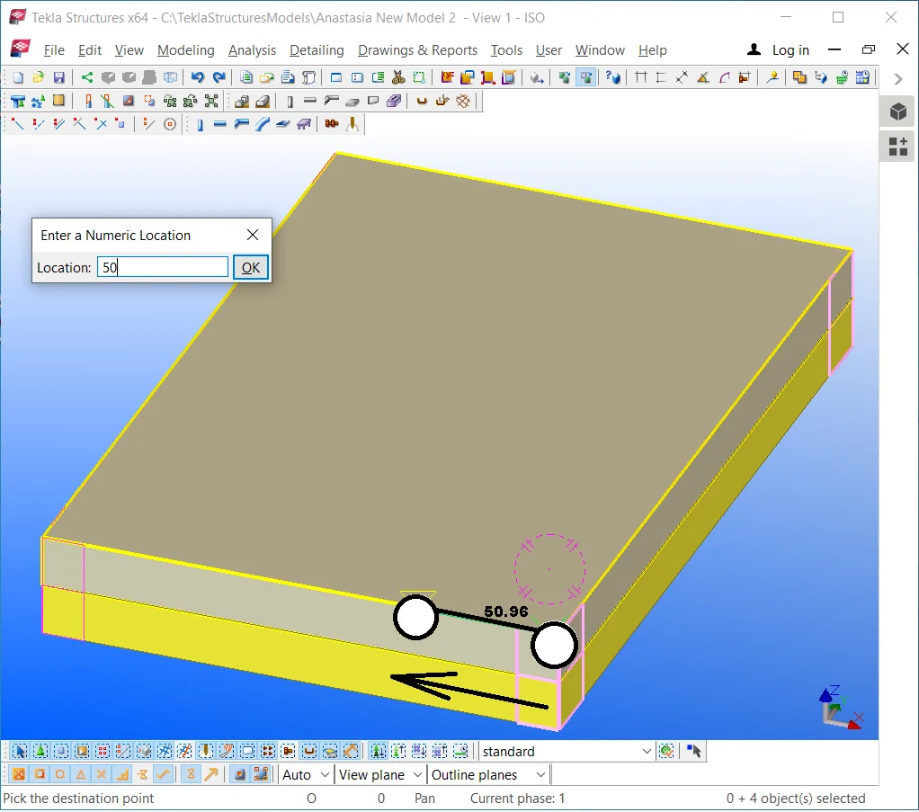
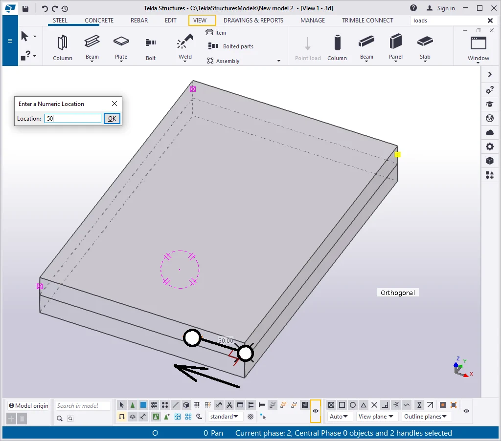
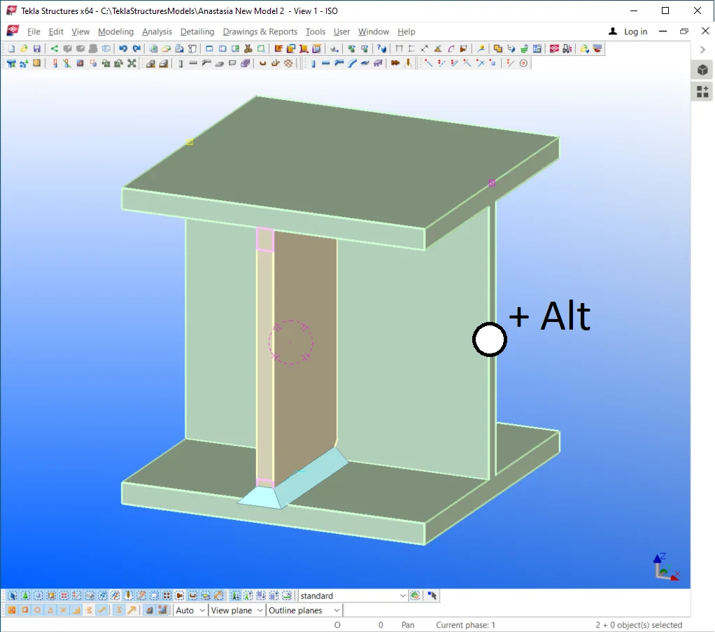
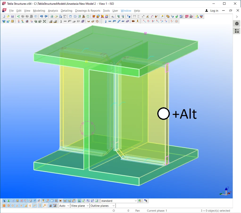
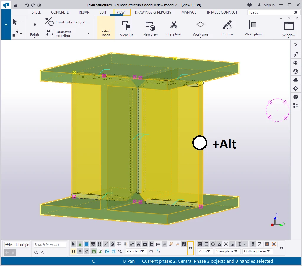
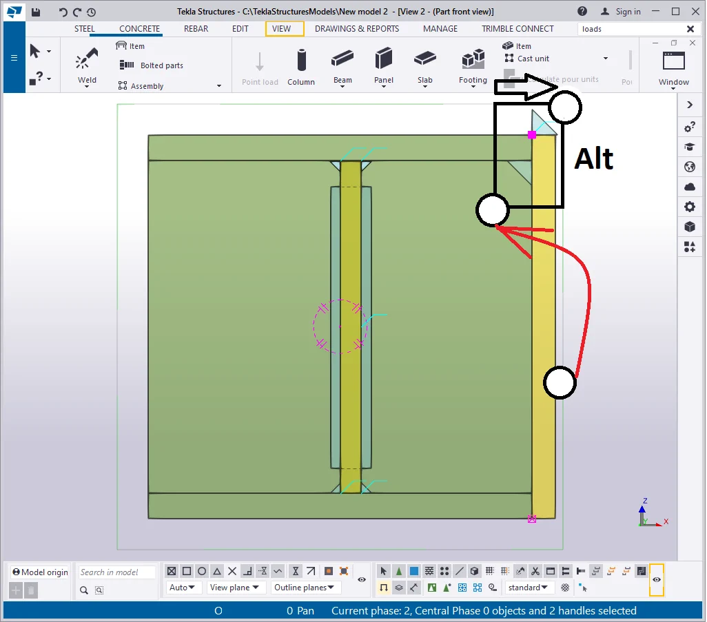
Click on the top plate, and by holding on the “Alt” key pressed,
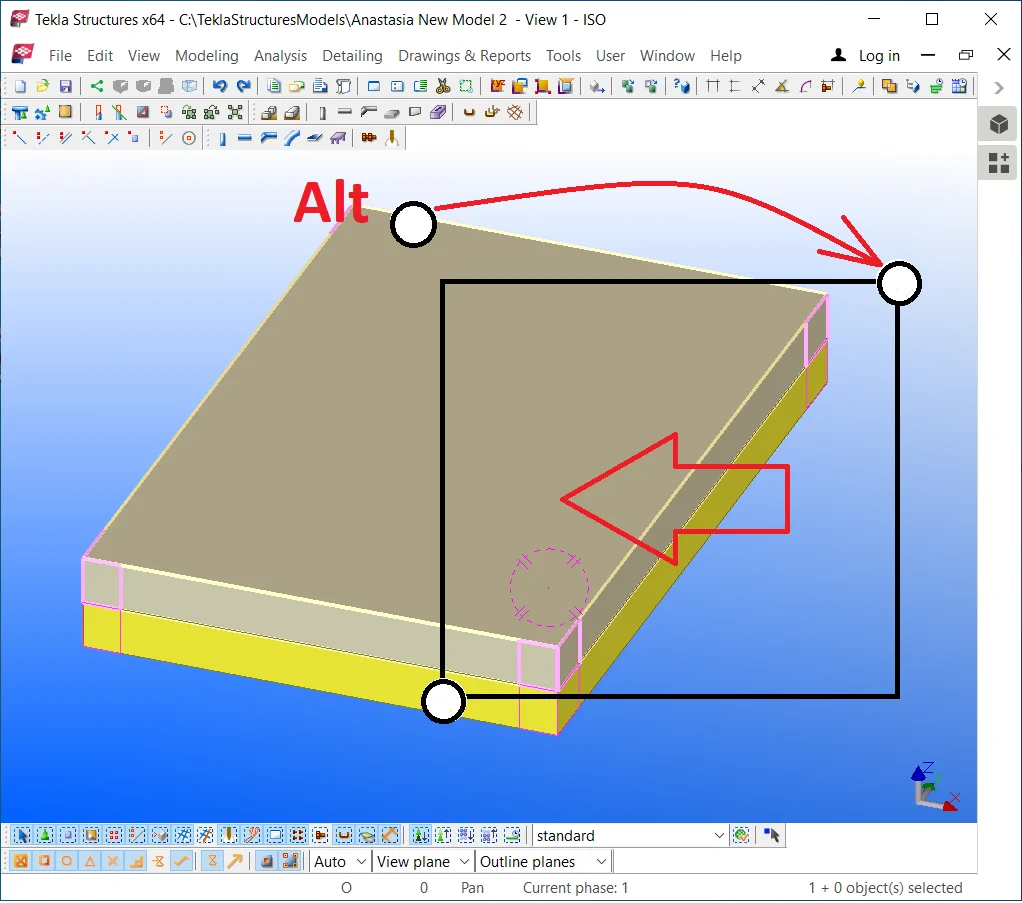
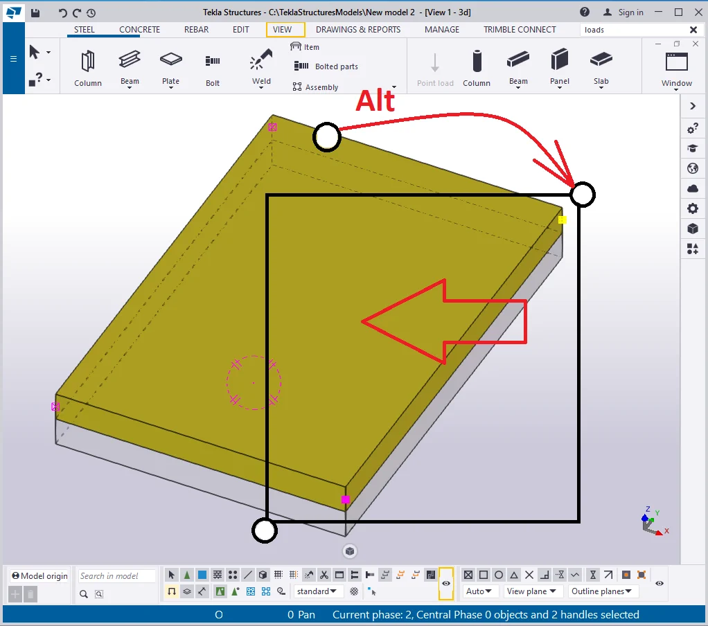
Move the points selected at 50 mm inwards to the plate.
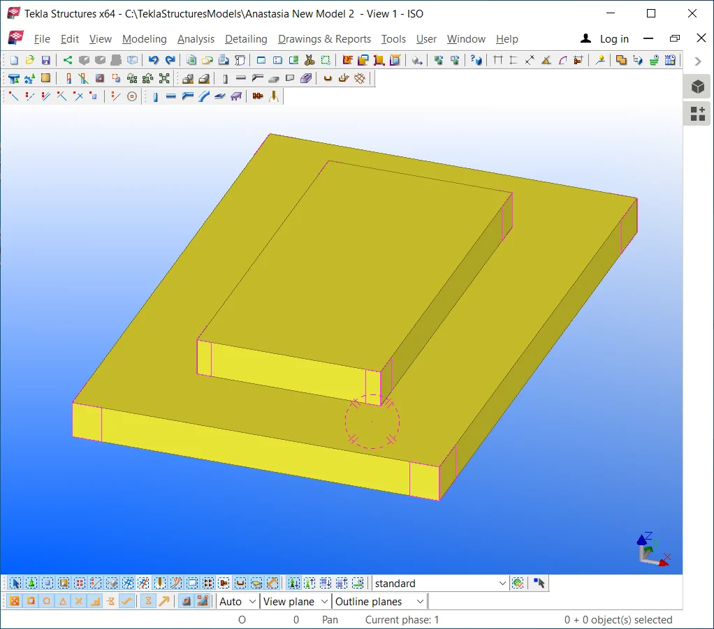
Proceed likewise for the other faces of the upper plate.
The result should be as presented in the below picture :

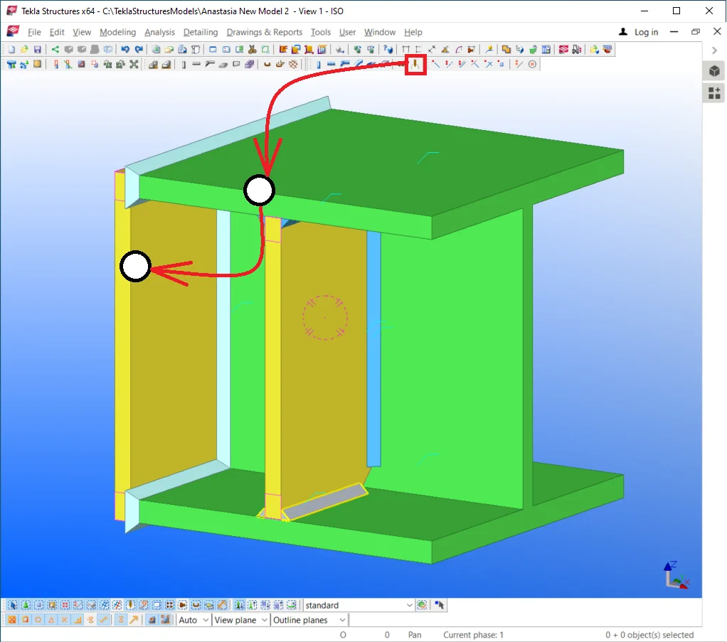
Now, let’s make sure that the view settings are configured for displaying
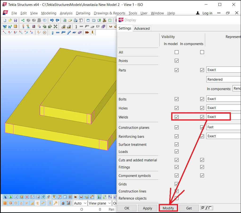
Close the “View settings” window and proceed to welding.

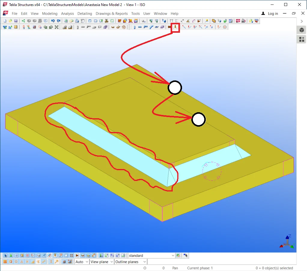
Note that it was of no convention to indicate the weld seam location. The software creates weld according to the weld properties configurations. Open the weld properties window by executing a double-click on the " Weld" tool icon. At the moment, the weld seam is passing around the edge of the part.
|
|
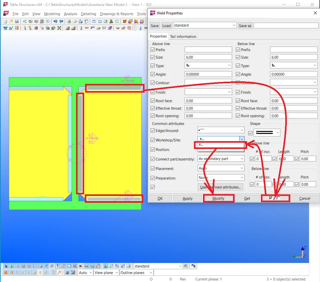
The symbol, indicating the weld seam location along a part edge (not around). It is one of the most frequently used weld seam types. |
|
|
The symbol, indicating the weld seam location around a part edges. It is applied when connecting round and square pipes, or any complex profile parts. |
Change the weld seam type to the first one
 .
.

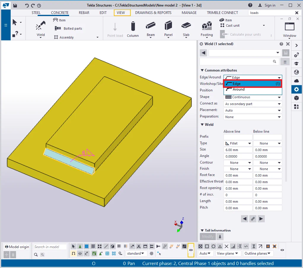
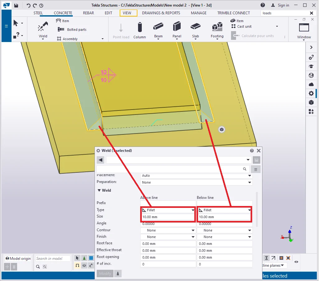
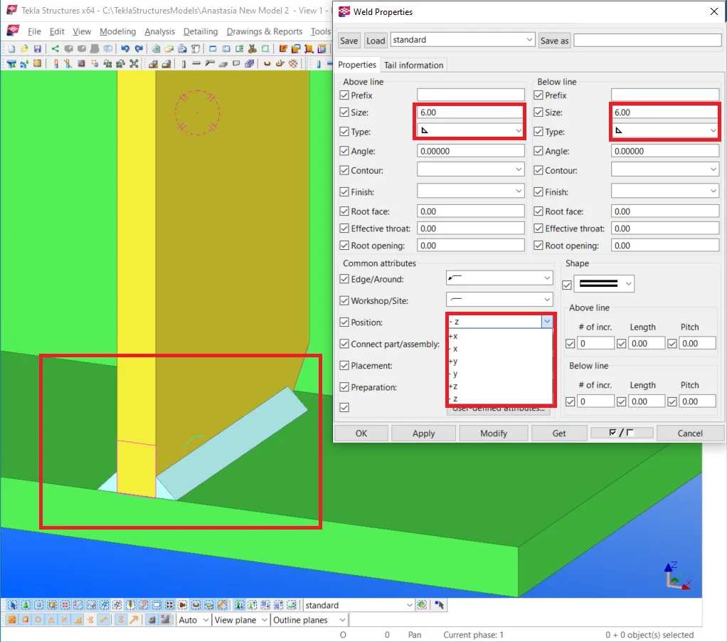
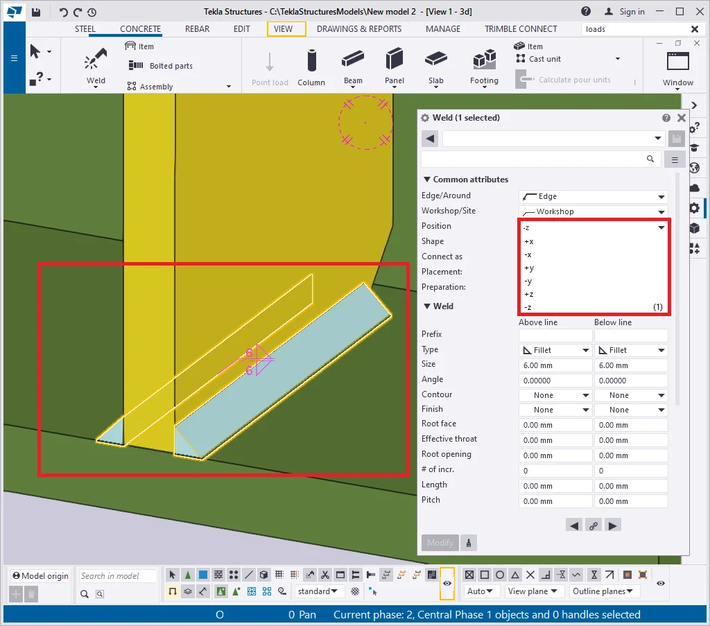
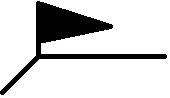
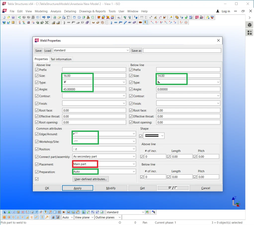
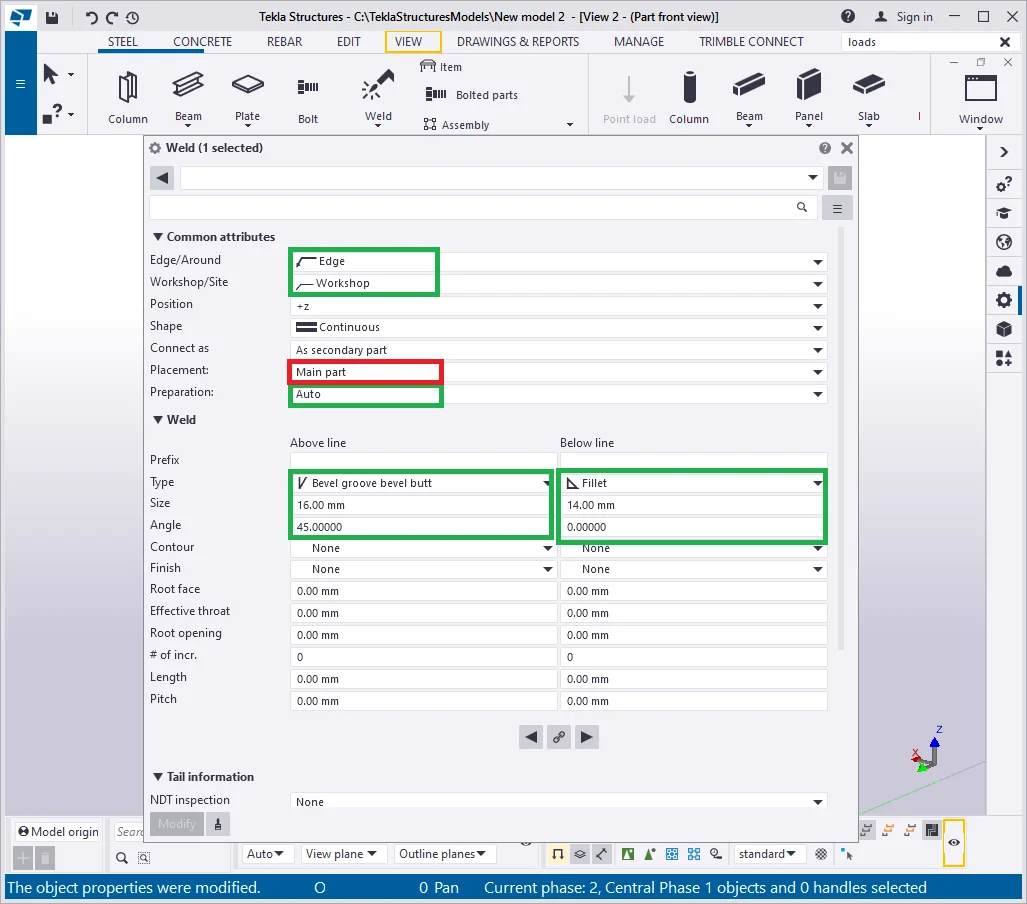
Depending on the default settings of the " Weld" tool, there are 1 or 2 seam lines displayed in the model. The weld seam is only one but might be specified to be applied from both sides of the part edge: above and below lines. Currently, the below weld line is switched off. In the below picture you can see color framed both weld lines set up fields.
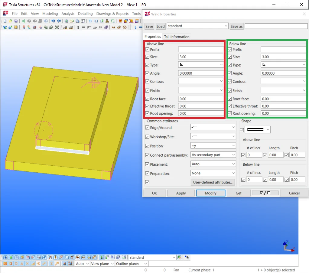
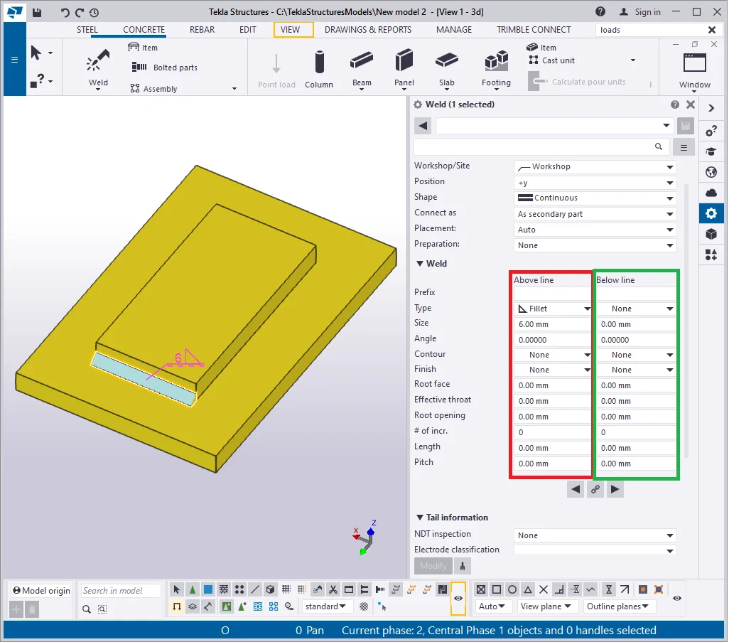
Let’s map the below line seam by indicating an arbitrary weld type and its size value different from zero, for example, 12 mm, to get a clear understanding of the fact that the weld seams can be of various dimensions.
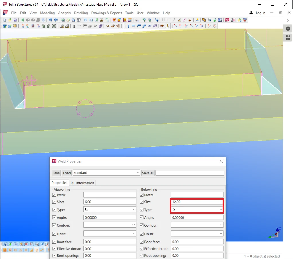
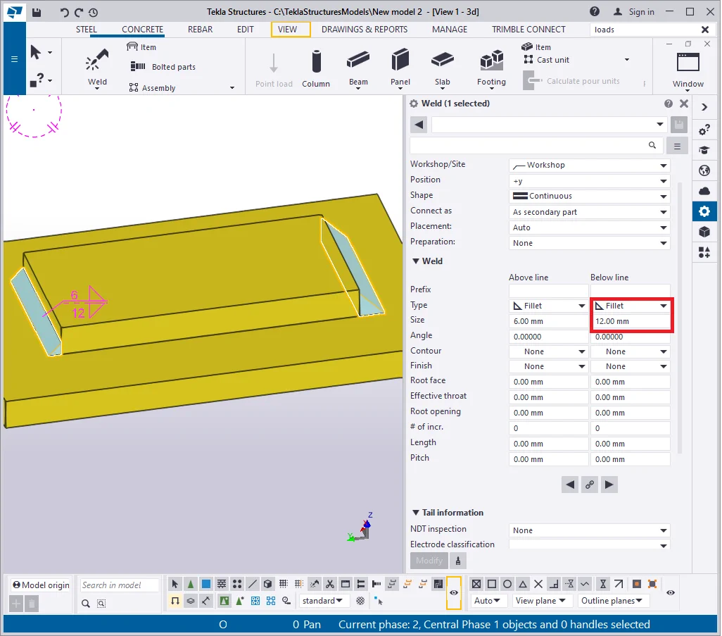
Hiding any welding line is done by indicating the “None” value

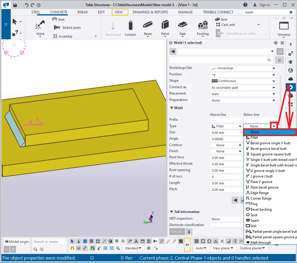
Also, the weld seam is not created in case its size value equals zero.
Let’s map out both weld lines of 10mm size.

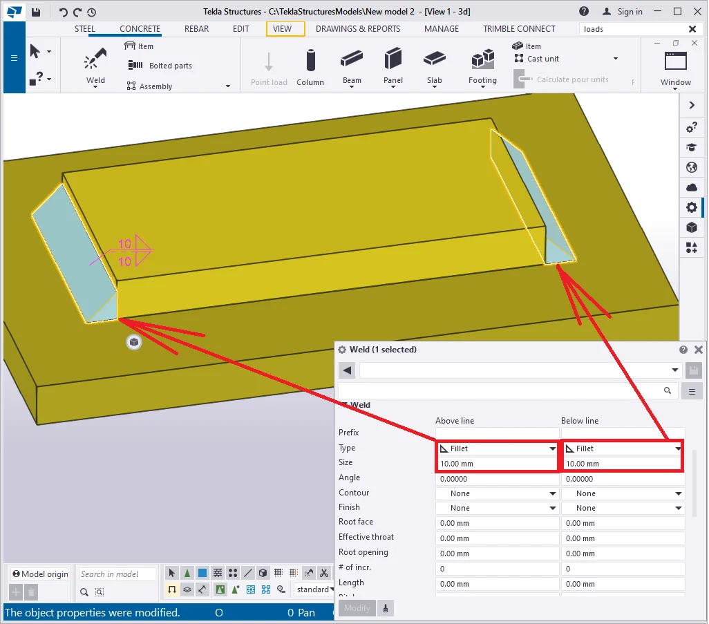
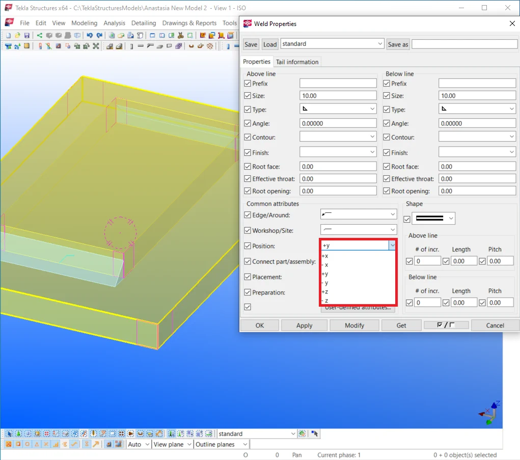
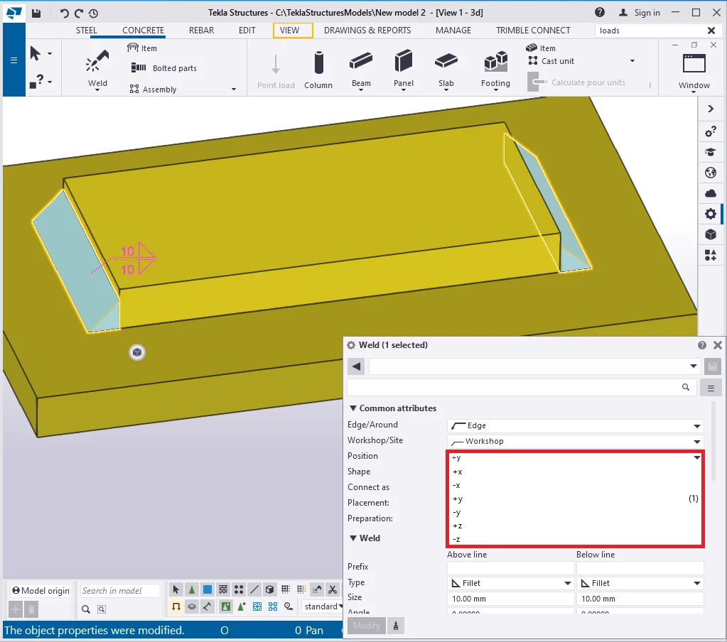
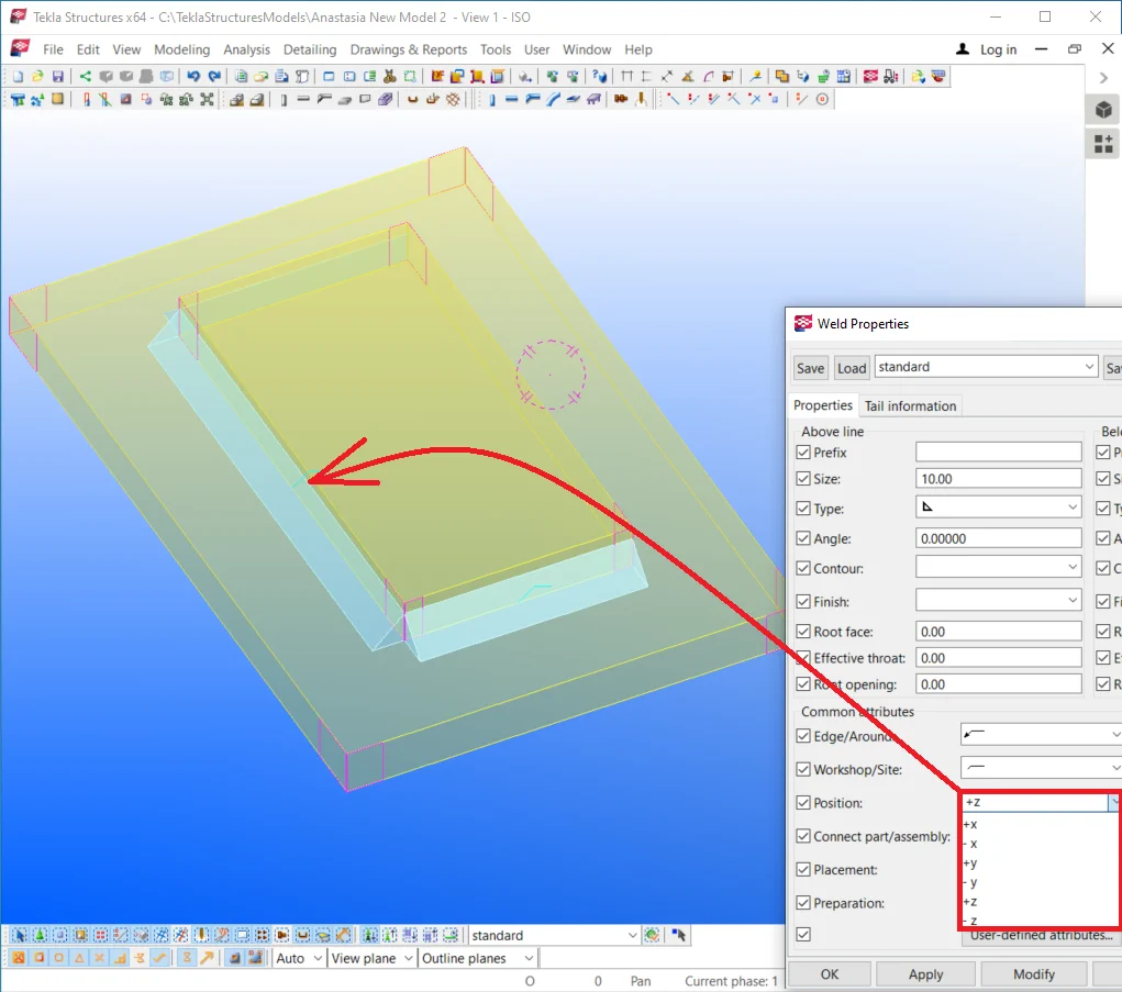
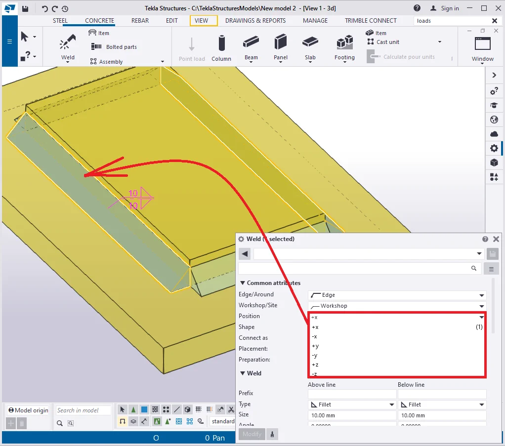
The “Position” field stands for lining up a weld in the model
As it is of no convention writing in the weld coordinates, thus the very
As you can see from the current example, the weld can subsist only along
Try out toggling between the “Position” field values.
Note there is no option to line up the weld seam bilaterally to the welded
Thus the solution is to create one more welded seam and configure it in
Go to the “Weld properties” menu and setup the welding
seam to the Type 1
, not Type 2
 . Select the appropriate weld seam position to get as presented
below.
. Select the appropriate weld seam position to get as presented
below.
Create the below line seam with the size value of 10 mm.

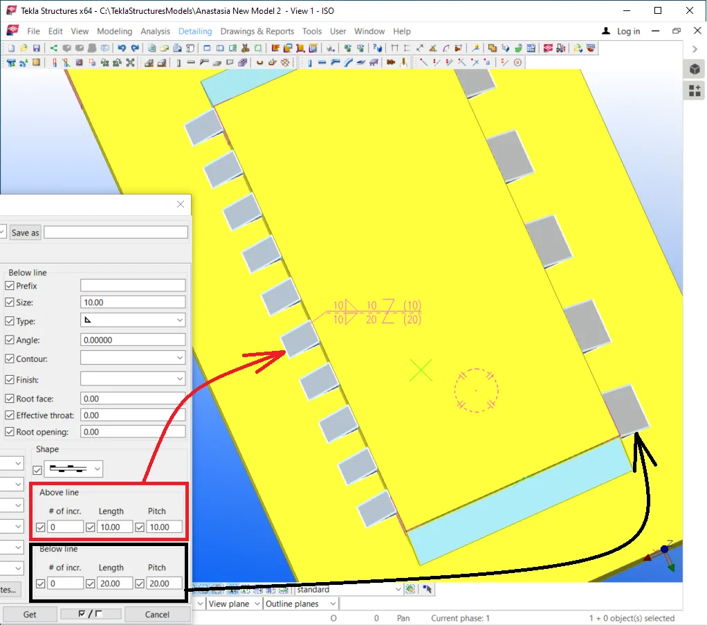
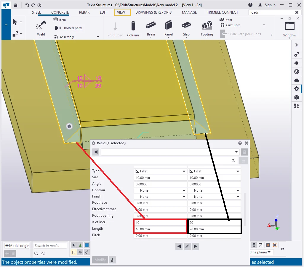
It is also possible to model various weld seam shapes, such as intermittent
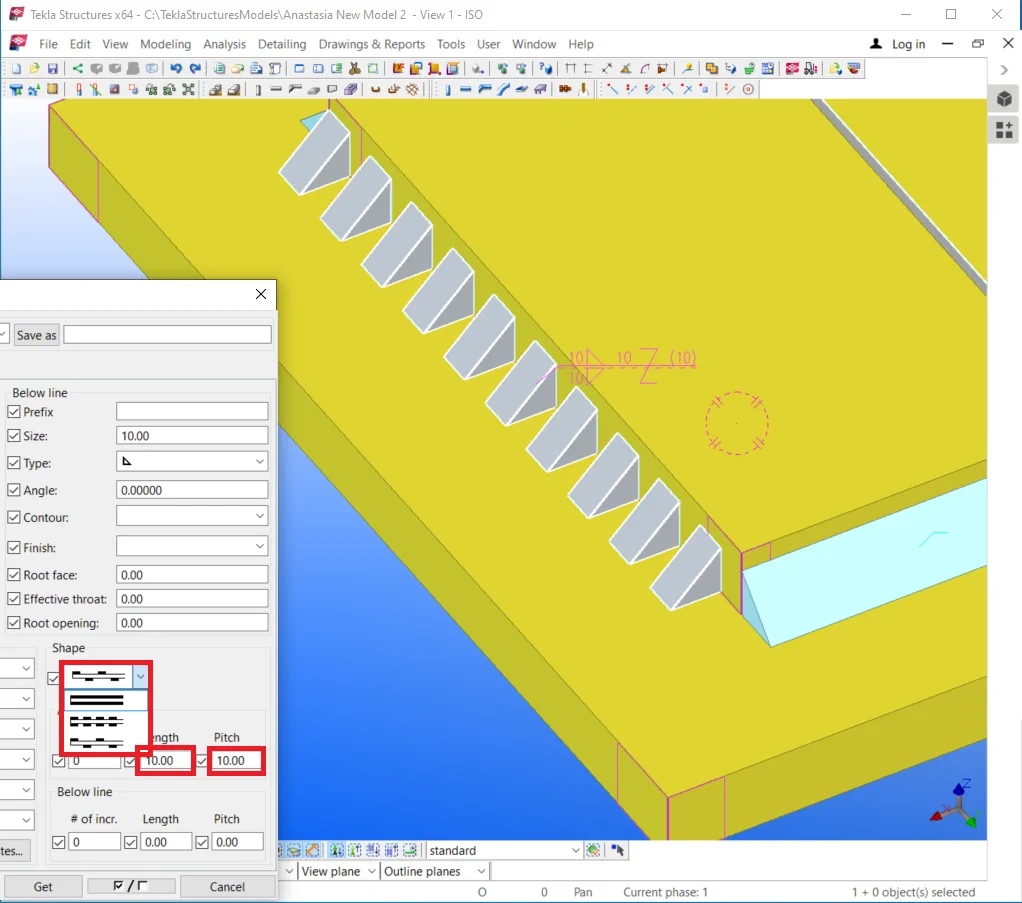

The intermittence of the seam lines is to be set up separately, same as
Set up the seams intermittence configurations as is shown below.
Deleting the top plate automatically deletes the welds.
None of the welds can exist without the welded parts to which it refers.

Now we are assured that the welded seams have been deleted along with
Let’s examine creating a butt type of weld. Copy the plate horizontally
Enable the “Create weld between parts” tool and weld up the


Switch the weld type from “Around”
to the “Edge” type
.

Now the weld seam has the triangle shape, though it is not viable in real
practice. Switch the weld type to the
 option. The current weld type requires setting up the bevel
angle value. Let’s set its value at 45 degrees.
option. The current weld type requires setting up the bevel
angle value. Let’s set its value at 45 degrees.
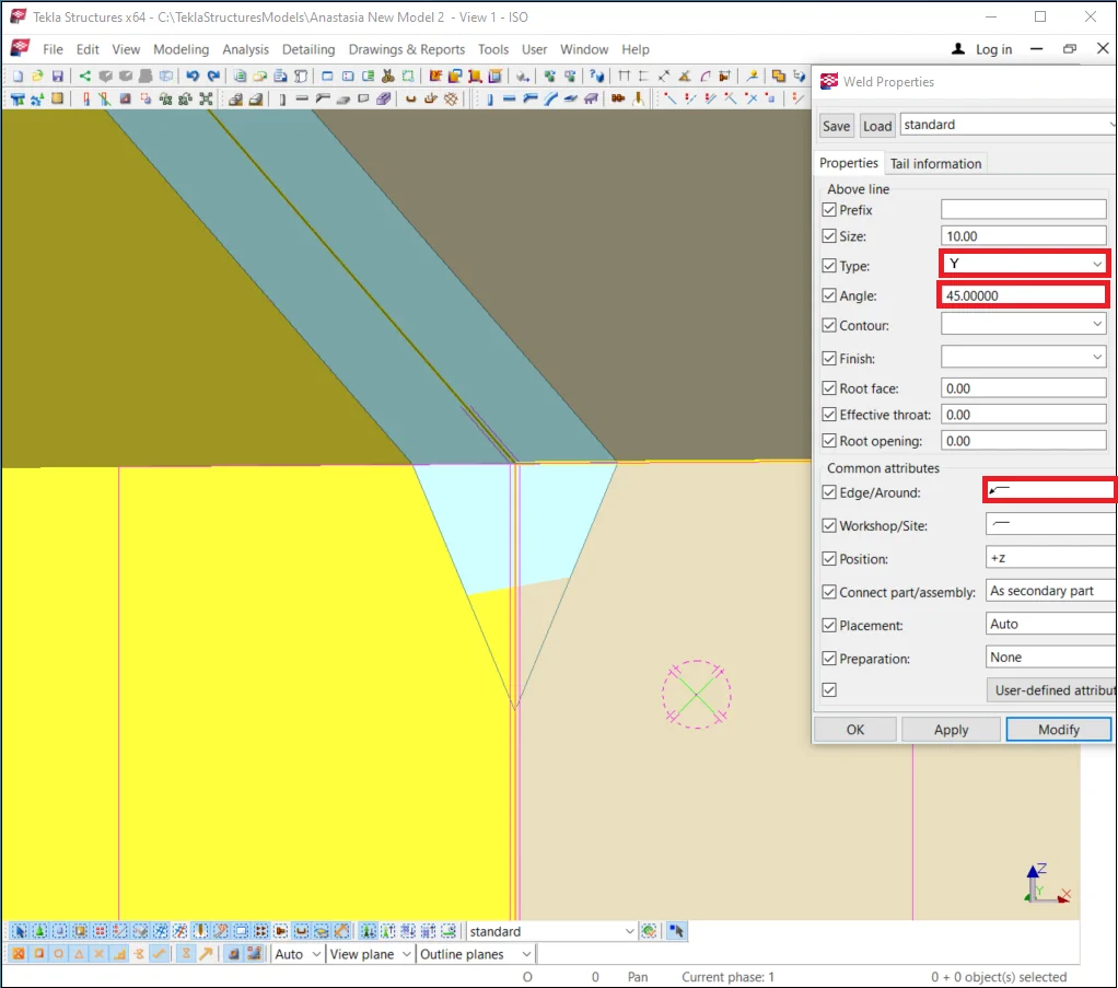

As you can see in the above picture, the weld seam has changed its type to the butt. Now before getting welded, parts shall get a prepared chamfer edge.
Also, it is important to leave an opening between the parts, thus
Let’s proceed by indicating the root opening value of 2mm.
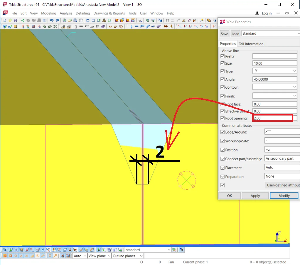
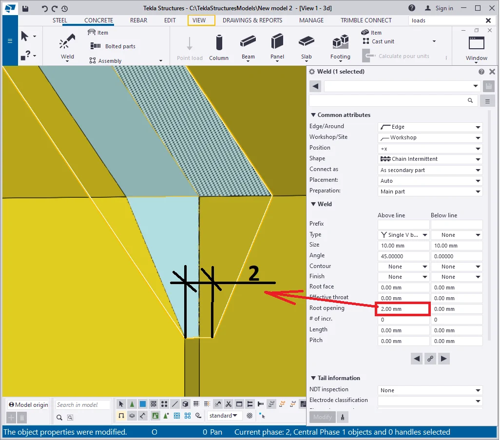
Also, make sure you indicate the root opening value for both: above and
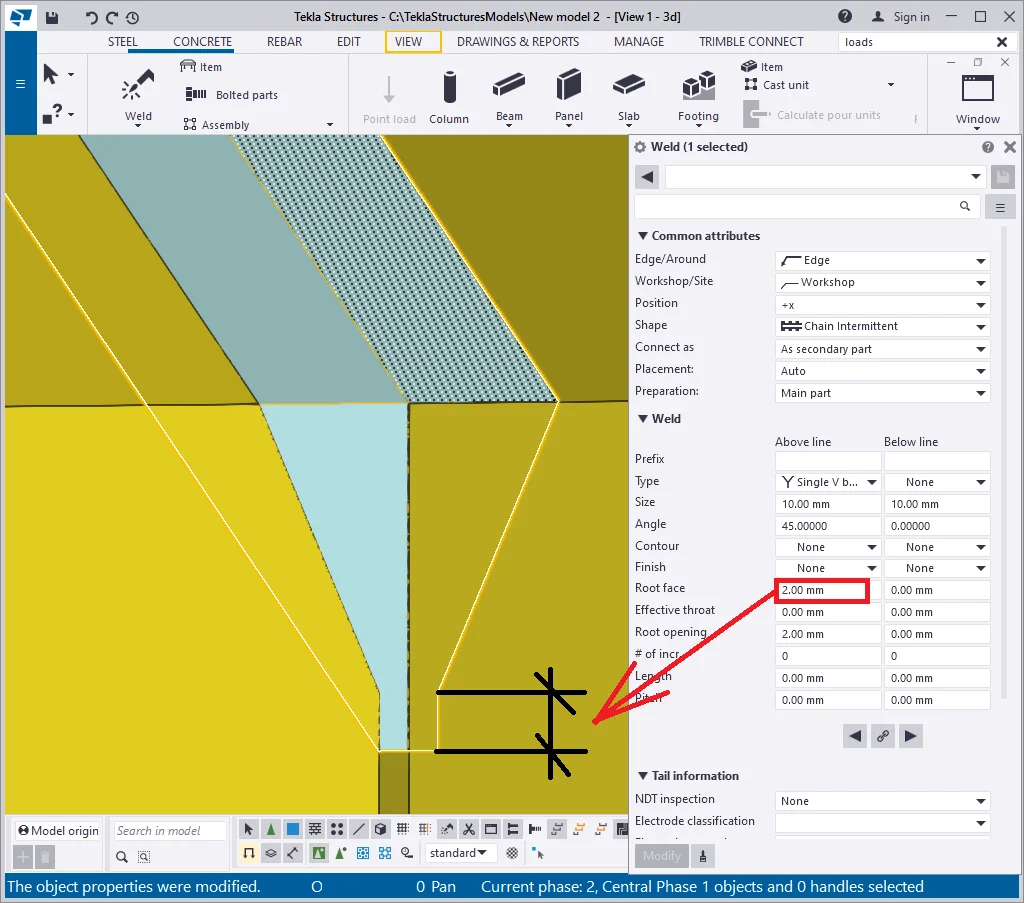
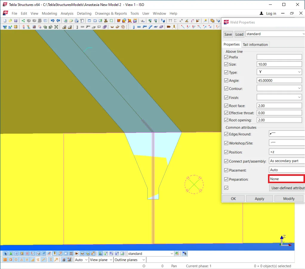
Let’s create the root face as well, where the plate thicknesses are 20mm, with 18 mm included as beveling thus the value to be written is 2 mm.

The "Preparation" field takes off the part’s body the welded seam volume by applying the added material substance. If the field value equals “None” then welding is reflected within the part body but does not subtract its volume or affect its geometry.

If the field value equals “Auto” then the geometry of the joinable parts will be subtracted by the welding seam bodies. The welding seams representation mode will also get modified, as the welds get their own space and transform into the only chamfer present at the drawing.

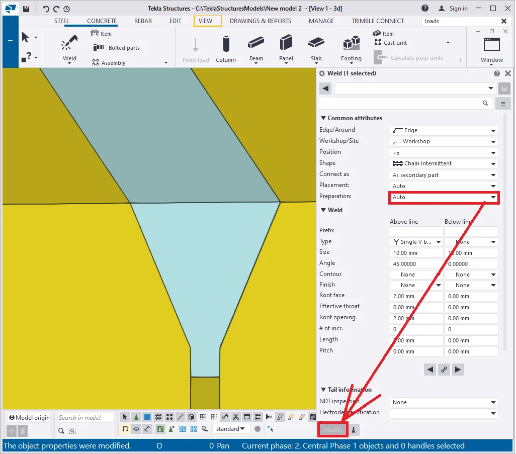
Thus it is possible to configure any edge of a part.
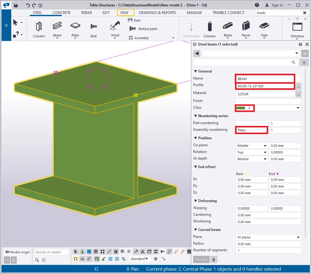
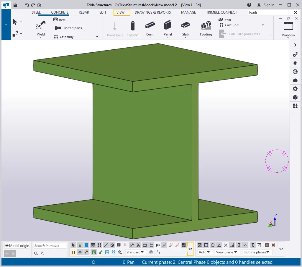
Let’s explore the case study where parts are joined to the profile
|
Part Prefix |
Assembly prefix |
Name |
Profile |
Class |
|
Leave blank |
Peter |
BEAM |
HI300-15-20*300 |
3 |
Configure the properties of the beam according to the above table.

Create a plate at the side of the beam as it is shown below, indicating
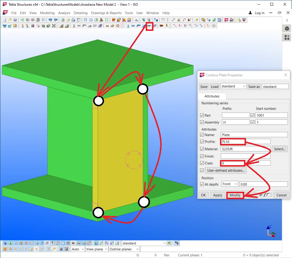
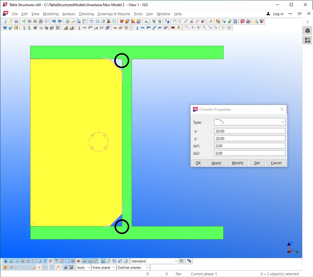
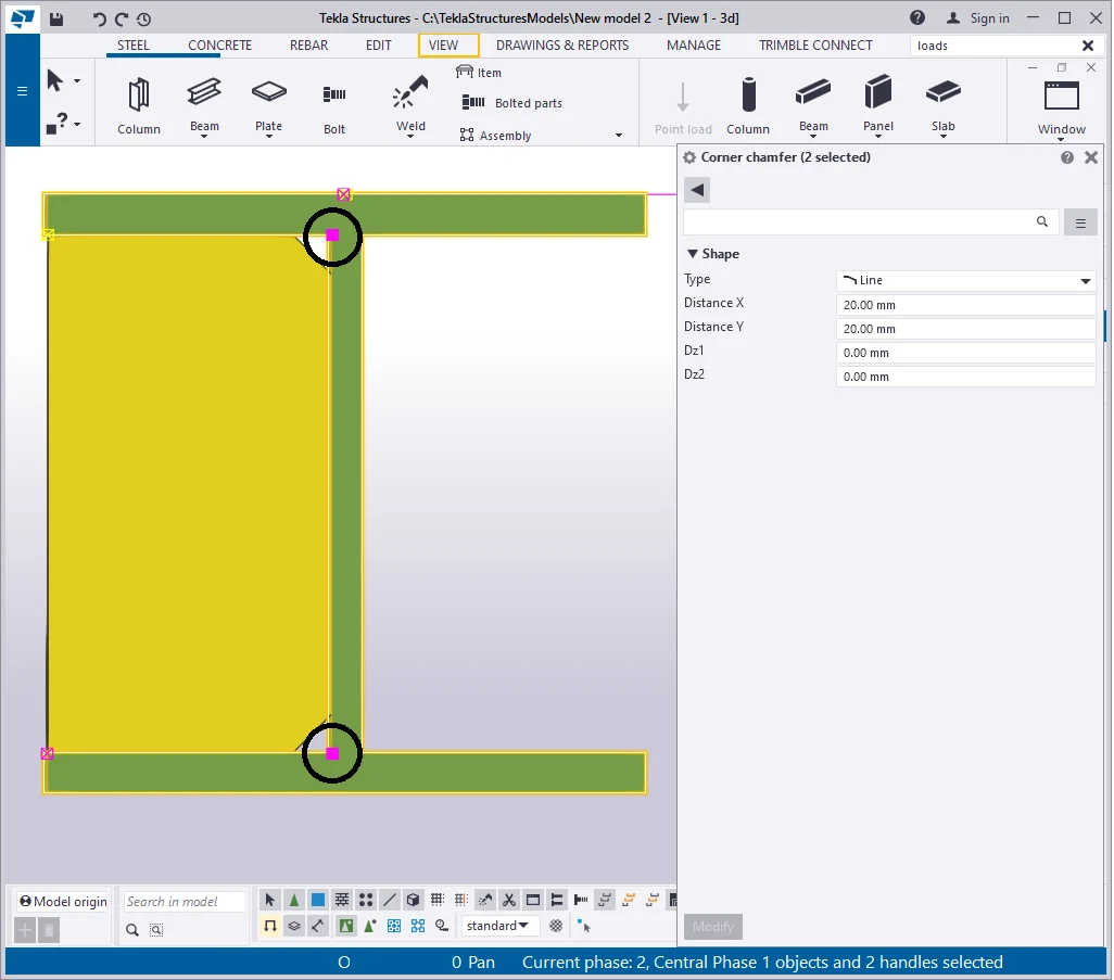
Click at the plate, and by holding on the “Alt” key pressed, select the points adjacent to the beam wall. Press the “Shift” key, and by a double click at a point, go to the “Chamfer properties” window.
Set up the angle value of 45 degrees, and the axial dimensions as 20 x
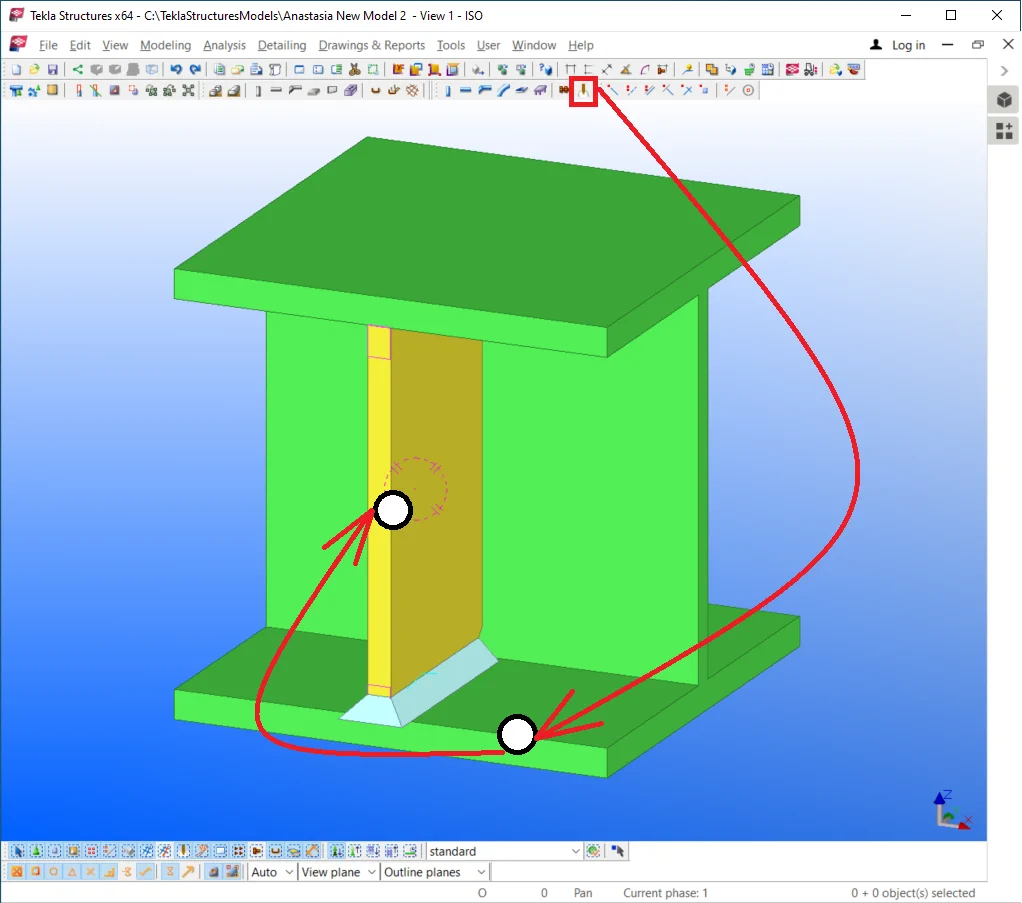
Move the plate to the beam center point by deploying the Ctrl+M hot key


Now let’s evaluate the notion of “assembly”, which is defined as a group of parts joined into an integral unit (assembly). In this case, welding is done by the manufacturer at the plant.
When creating welds it is of high importance to firstly select the beam, thus the assembly title will coincide with its name, but the beam will become the main component of the assembly.
Further on, when welding up parts in the TS first object to be selected
The location of the welded seams is of no particular importance, as the
To select an assembly it is sufficient to make a click at any of its objects
Let’s adjust the welding seam: switch it’s type from the “Around”
to the “Edge”
and set up the weld size at 6 mm bilaterally, Fillet type
-
 .
.
Toggle between the position options until the weld seam gets aligned as shown in the picture below, thus connecting the bottom plate line to the beam .
The position field coordinates may vary depending on the beam drawing
The single weld is not enough for joining the plate to the beam, though
Create one more weld seam to be aligned along the beam wall similar to the below picture. The new weld seam’s configurations are the same as the previous ones, except for the position parameter value.

By analogy create the 3rd weld seam and configure it to the position type
Make sure you indicate the beam as the main part of the assembly.

Thus the plate is completely welded to the beam.
One of the most important welded seam properties is that it can not exist
Deleting the plate automatically deletes the welds, which are not just

The beam got cleared up off the welds. Restore the welded plate by enabling
Try out executing "Copy Special-Mirror" of the plate to the other side of the beam. For this, press the Ctrl+P hotkey combination to go to the view plane.
Make sure that the Z-axis is perpendicular to the eye gaze direction,

Select the plate, and in the right-click menu, proceed to the “Copy
Another important property of the welds is that they are copied along with the welded parts to which they refer, even though welds have not been selected. Also, note that this condition plays out only in case there is available appropriate geometry. For example, copying the plate to a blank space will not duplicate the weld seams, as there is no connectable object to the plate.
In the below picture you can see that the duplicated plate got adjusted
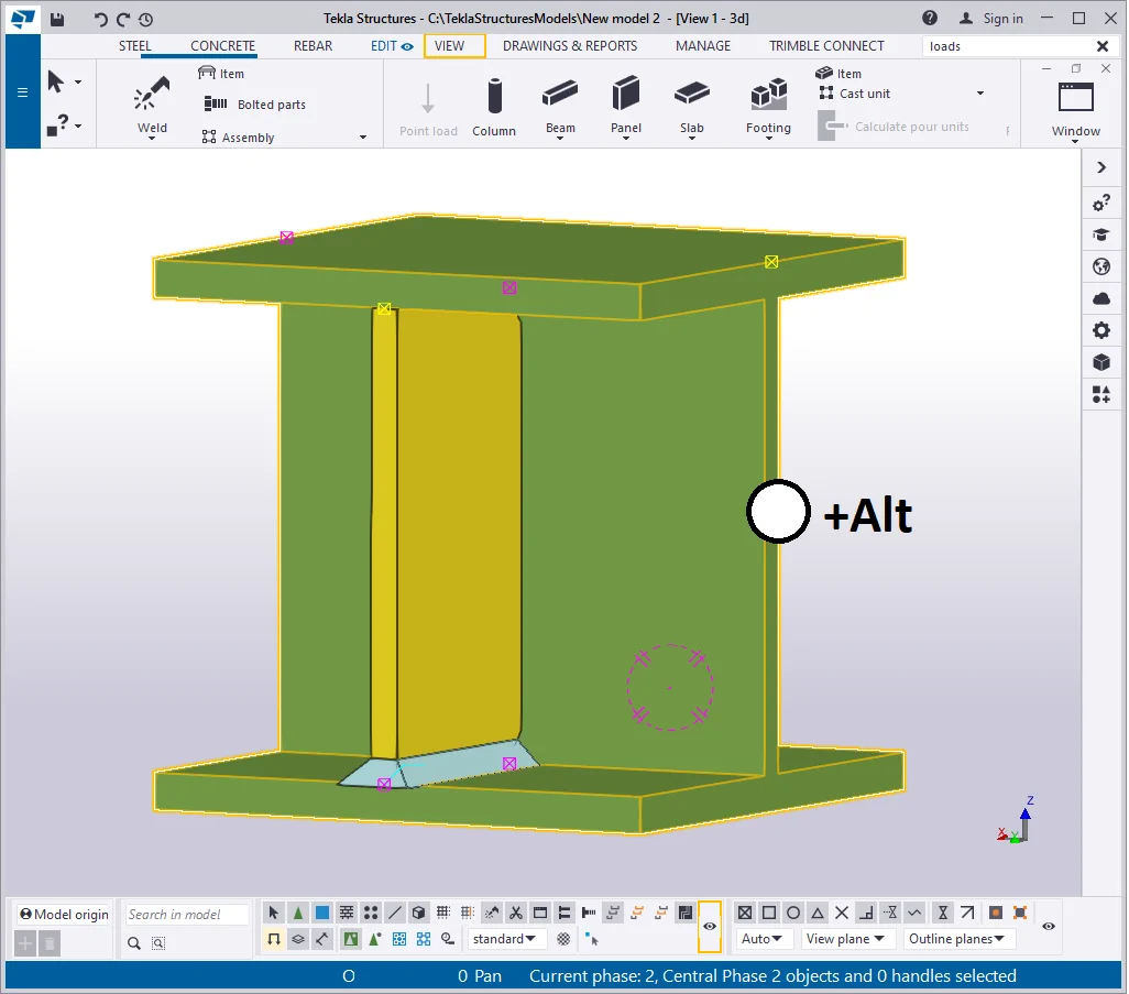
Check this out by holding on to the Alt key pressed and clicking at the
As you can see all the objects were selected, even though initially we
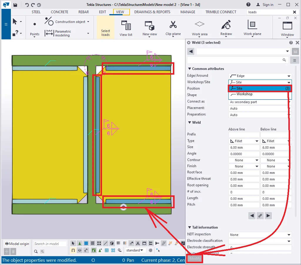
Let’s explore the "Workshop
 / Site" attribute
 .
.
This parameter stands for defining whether the parts will get included
in the assembly (into a common drawing). Indicating the “Workshop”
weld type contributes to welding the parts at the plant, thus they are
to be included in a common assembly drawing. Select all the weld seams
of the plate and switch the weld type to the “Site” class
.
Repeatedly select the assembly by applying the "Alt" key.
To assure better visibility go to the Ctrl+5 display mode.
From now on, the parts are available on the weld seams but still are not
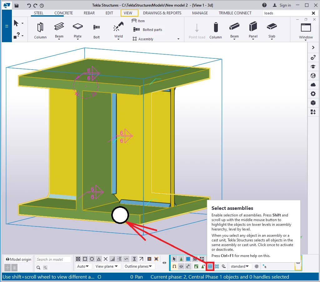
There is a separate tool for selecting an assembly as an object type, not a kit of objects. This tool allows editing assembly properties as well as selecting it without holding on any key pressed.
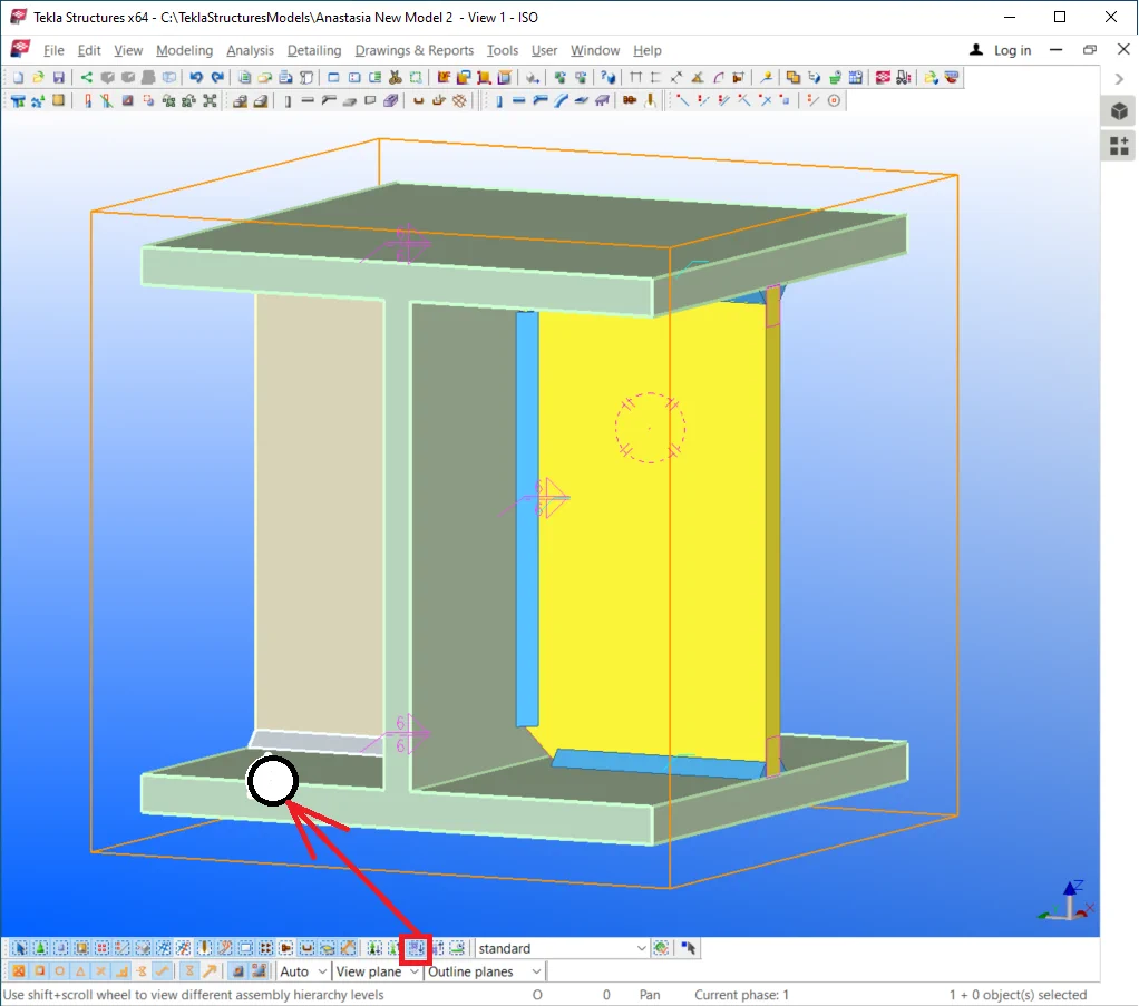
Note that the selected objects have a different visual display: the assembly object is framed with block faces, outlining its dimensions, and the main assembly part gets rendered in orange color when selecting the assembly by the right-click menu “Inquire” tab.
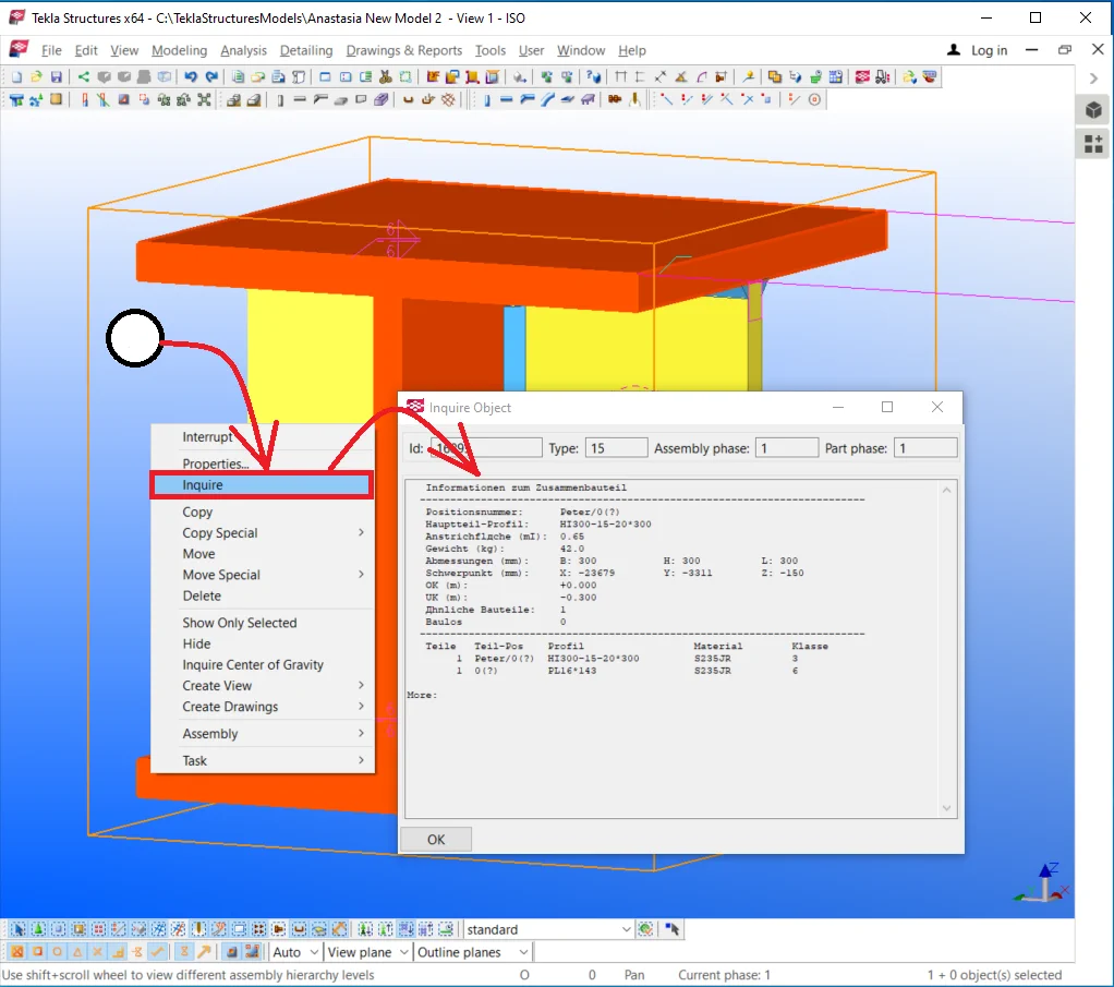
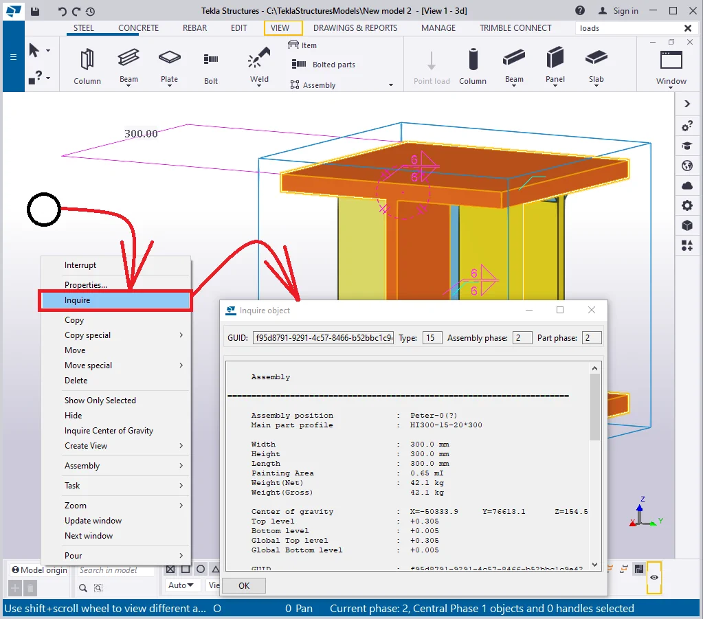
The “Inquire object” tab runs the assembly text report. We will examine in detail the issue of creating and editing such reports in the following chapters. Double-click at the main assembly object (orange colored) runs the assembly properties menu which is completely different from the assembly report.
At the moment, let’s make it a rule, not to bring any changes to
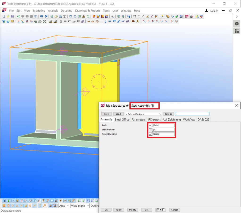
|
нTekla Structures v21.1 |
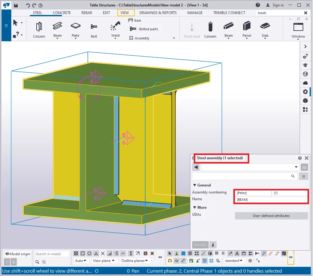
Tekla Structures v2021 |
|
|
|
It is forbidden to edit the “Assembly numbering” and the “Name” fields values, which are included in the square parentheses, thus denoting the default status of the lines.
The assembly properties menu can be opened by using standard selecting
Select any part, and in the right-click menu go to the “Inquire” tab and select the “Assembly” option. The assembly automatically gets highlighted, and the “Inquire object” report pop-ups on the view.
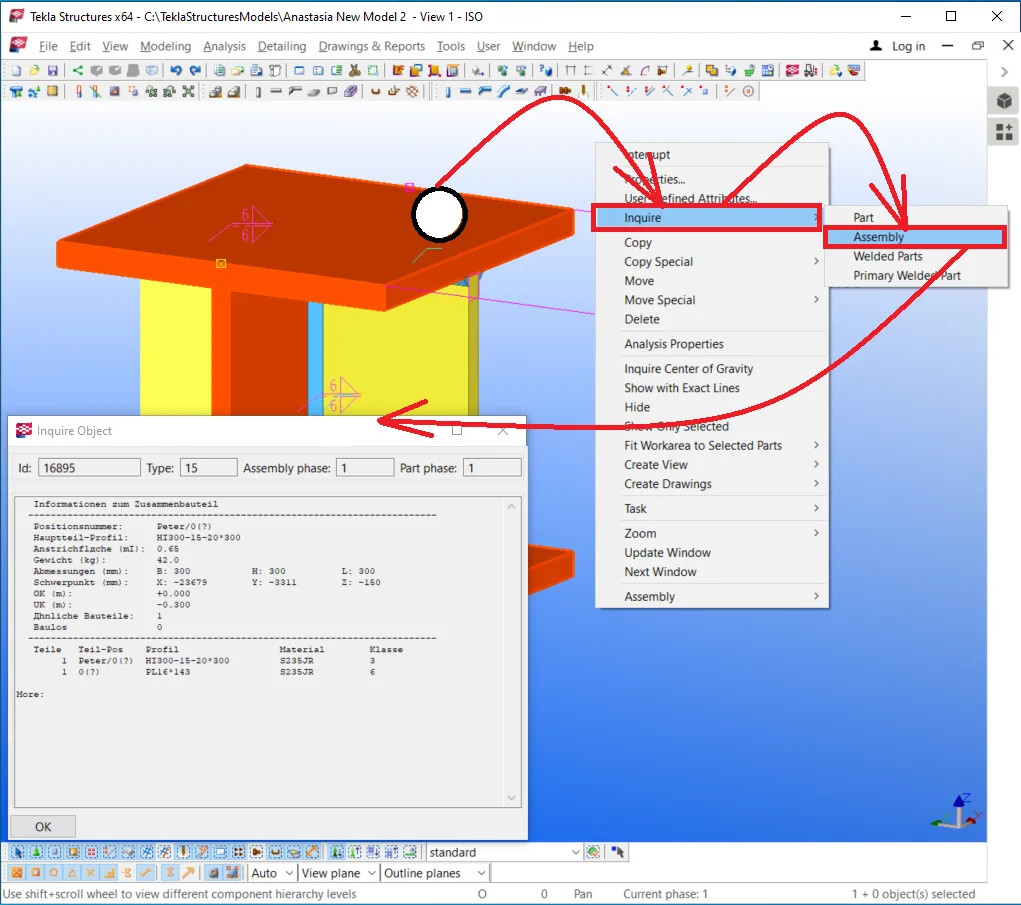

In the “Inquire object” report there is available all essential
At the moment, let’s, first of all, get the assembly name -Peter-0(?), where the question mark stands for notifying that the assembly number had not been assigned yet, as numbering was not carried out yet. The numbering topic will be examined in the creating drawings case study.
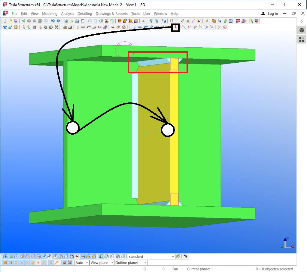
Let’s examine one more welding component type, such as the endplate. Create an endplate with its points located at the I-beam edges. Set up its width parameter at 18 mm.
Weld up the endplate to the I-beam. It is important to indicate the beam as the first assembly component with the purpose that the assembly gains the prefix numbering of the main component.
Locate the weld seam above the I-beam.
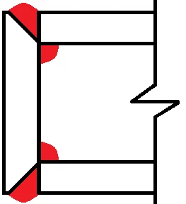
It is obvious that the weld seam can not be created as it is shown in the above picture. Welding up the parts with no edge preparation fails at realizing a full penetration weld, which comes evident after executing the parts surface treatment.
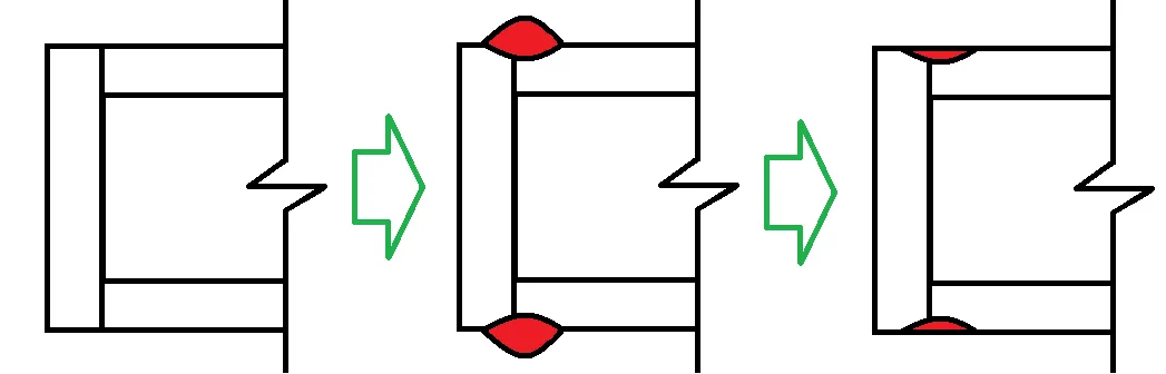
Thus when welding up the endplate definite measures are to be taken to assure full penetration. There are the following alternate solutions to this matter:
|
Increasing edge plate’s dimensions |
Reducing edge plate’s dimensions |
Executing the edge preparation at plate |
Executing the edge preparation at beam |
|
|
|
|
|
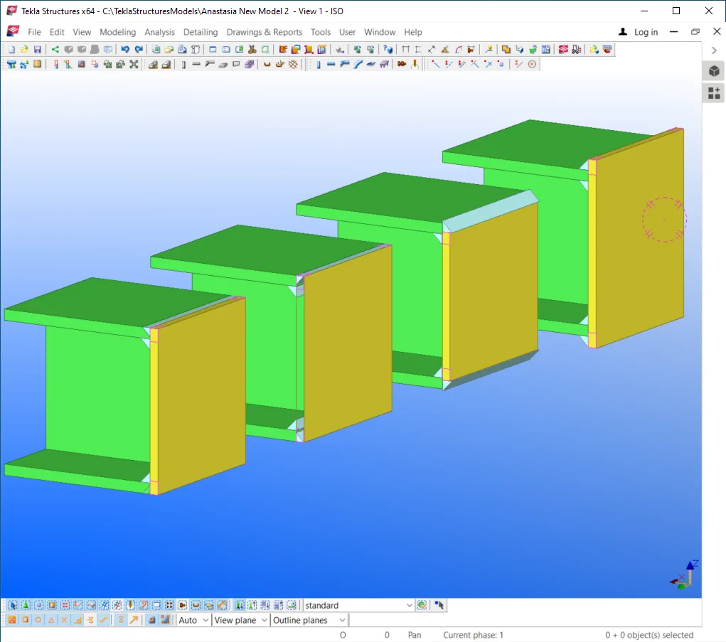
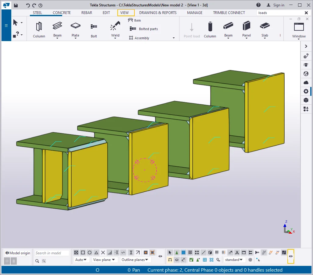
Let’s copy the beam with the edge plate 3 more times and implement

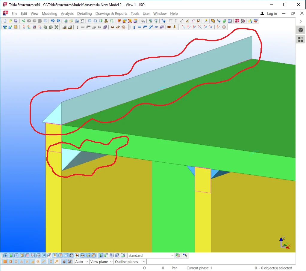
Type 1- Increasing the dimensions of the edge plate.
Let’s try out the first solution which implies increasing the plate’s

Similarly to the above proceed for the bottom points of the plate, by
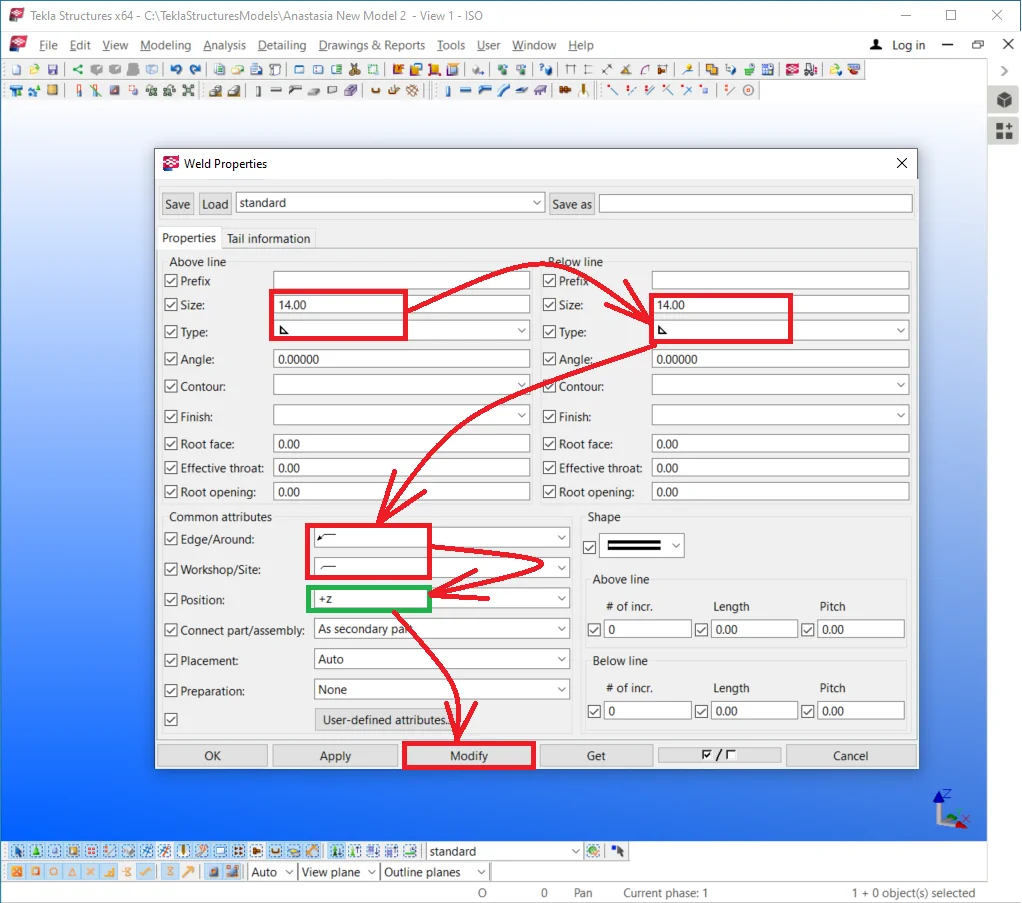
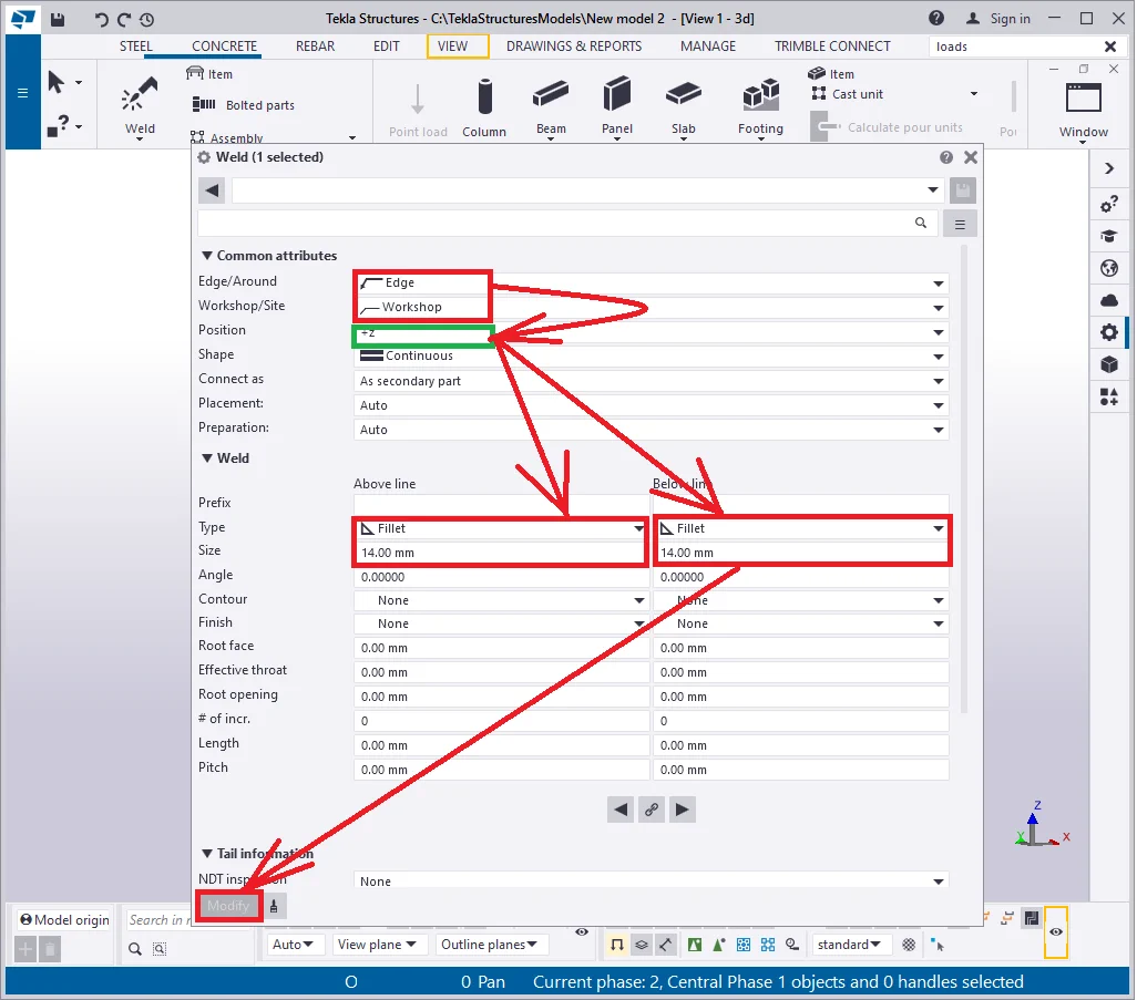
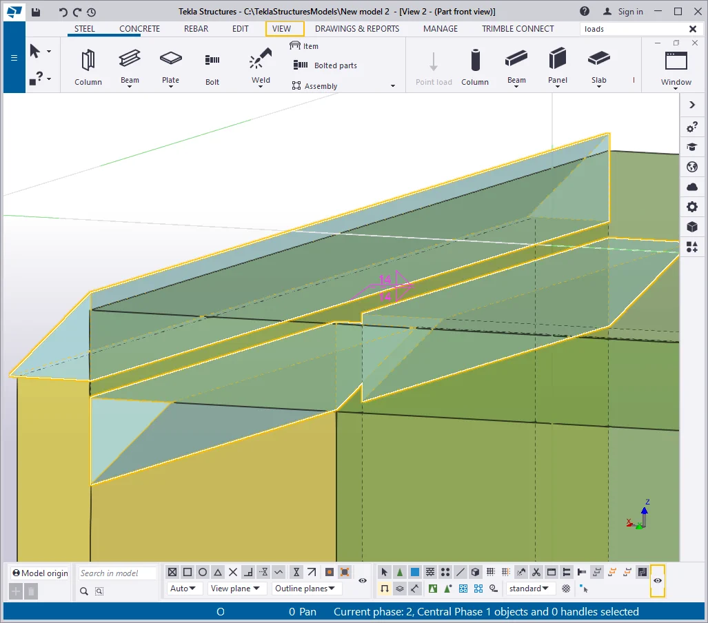
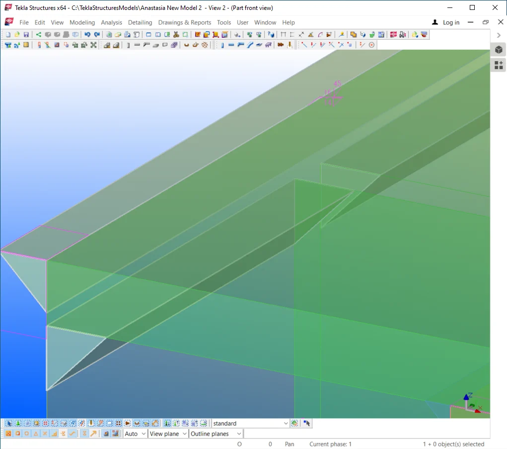
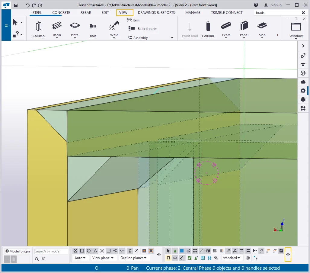
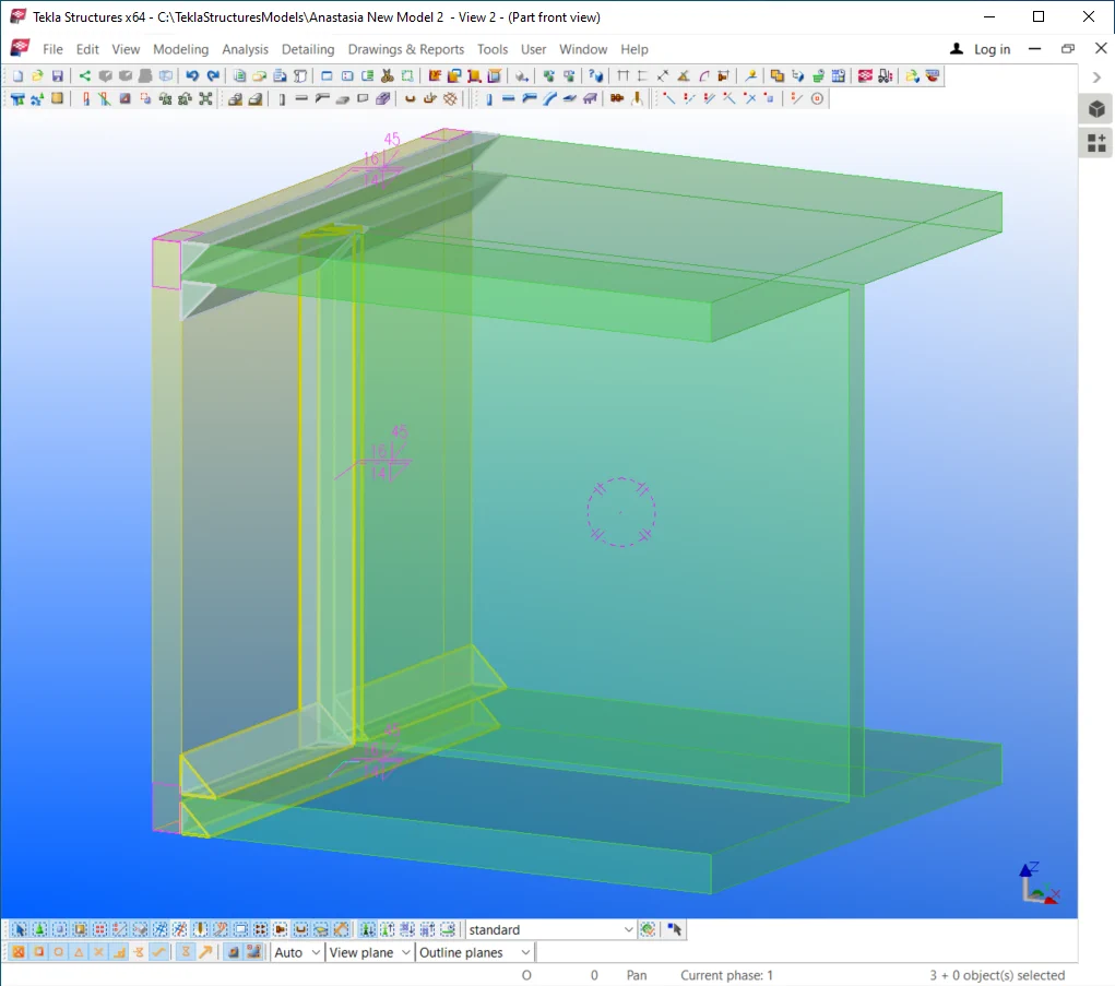
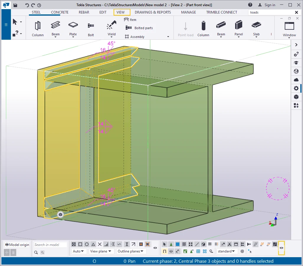
Make sure that welds are set out visible at the "Exact" representation mode at the “Display” menu of the "View settings". At the "Welds settings" menu configure the welding seam to be bilateral, and of the size equal to 14 mm. It is important to mention that the welding seam size is determined by calculation.
The size value of 14 mm is an arbitrary rate, thus do not percept the

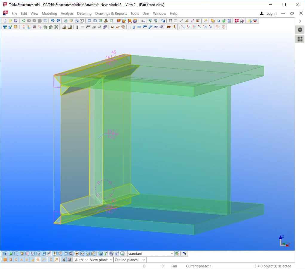
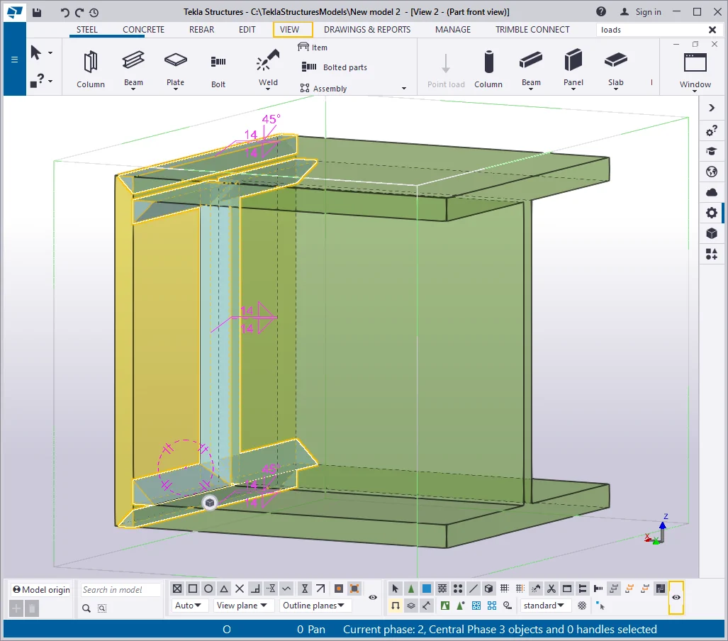
Create additional weld seams by toggling between the “Position”

Close the current view and other default views of the part, except for
Type 2- Reducing the dimensions of the endplate
Adjust the dimensions of the plate according to the below picture.

Pay attention that the flange thickness of the beam is 20 mm, but the
Thus the offset value shall not exceed the beam flange thickness.
Create weld seams according to the below picture.

Close the current view and other default views of the part, except for
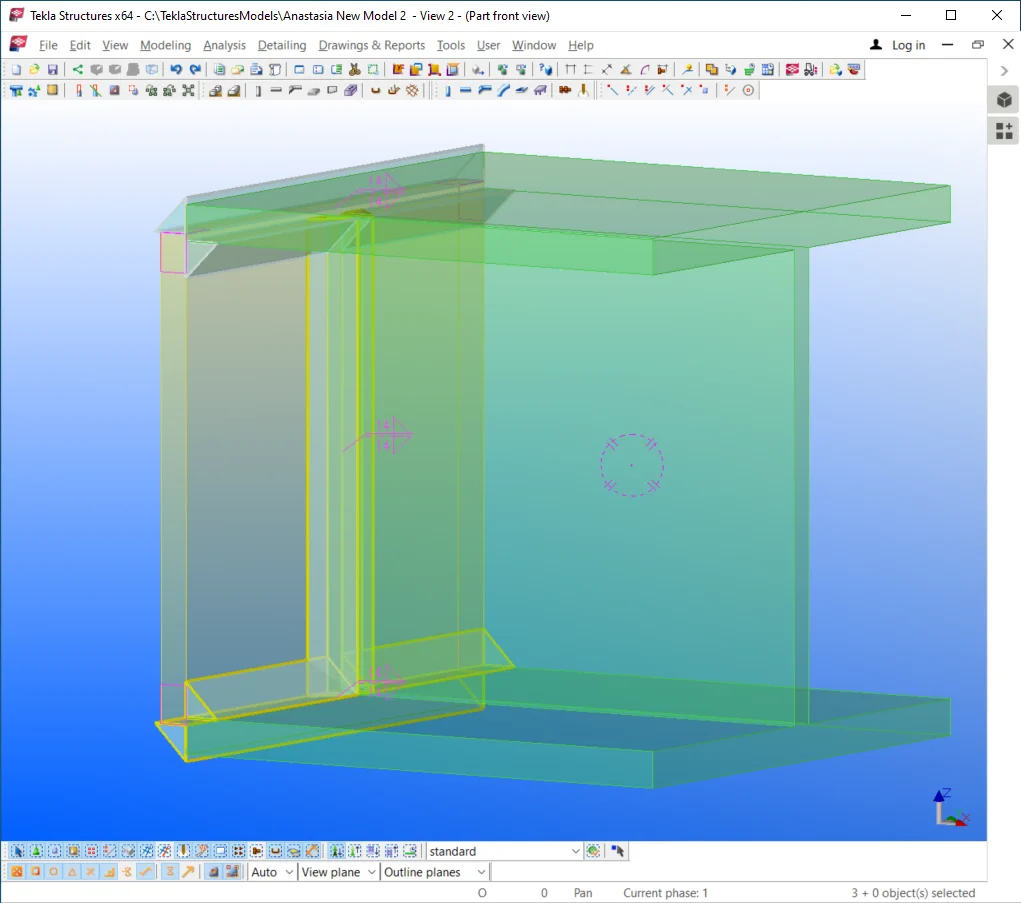
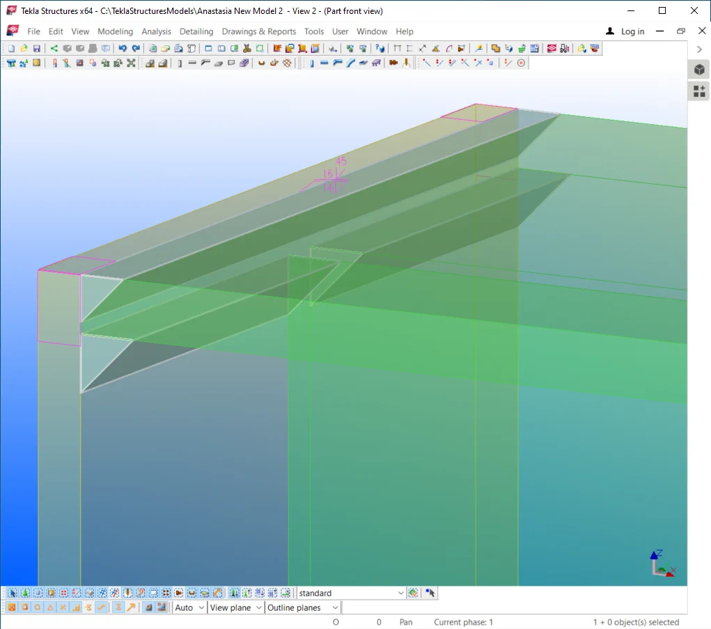
Type 3- Executing the edge preparation of the plate
Let’s create the part’s default views and get to the part’s "Side view". Adjust the weld seam in the way to get grooved into the part.
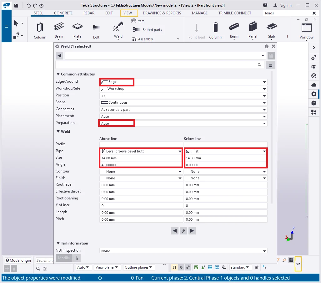
Switch the weld type to the "Bevel groove bevel butt" option.
Specifically for this welding type, it is compulsory to
 indicate the welding chord and the angle parameter values, otherwise the
weld seam is not created. Set out the “Preparation” field as
“Auto”.
indicate the welding chord and the angle parameter values, otherwise the
weld seam is not created. Set out the “Preparation” field as
“Auto”.
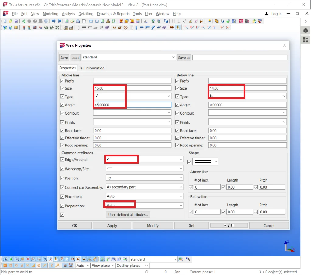
Refer to the below to align the weld seam correctly.
Create all the weld seams required. Note that the seams along the I-beam
Close the current view and other default views of the part, except for
the "Top view" window.
Type 4 тип - Executing the edge preparation of the beam
Set out the edge preparation parameters similar to the previous case study, except for indicating the “Placement” field value as “Main part”. In the current case study, the beam is the main assembly component, thus the edge preparation is to be applied to it, according to the “Placement” parameter.
Compare your results to the below:
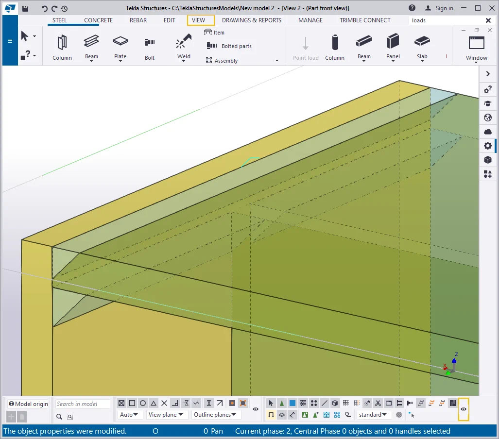
Add up the rest seams.
Keep in mind that the seams along the I-beam wall shall not have
Thus we have examined several edge preparation solutions and realized
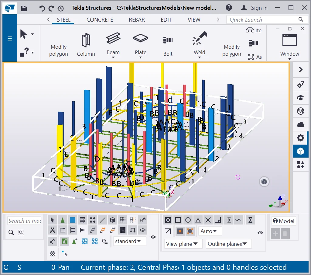
A selected view has a red (yellow) frame along its perimeter.
Switching the view is easily done by a left-click at any place of the
By holding on to the Ctrl key pressed and by making left-clicks, it is
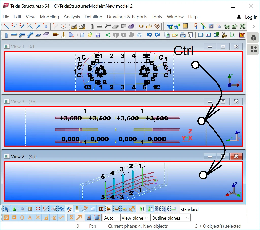
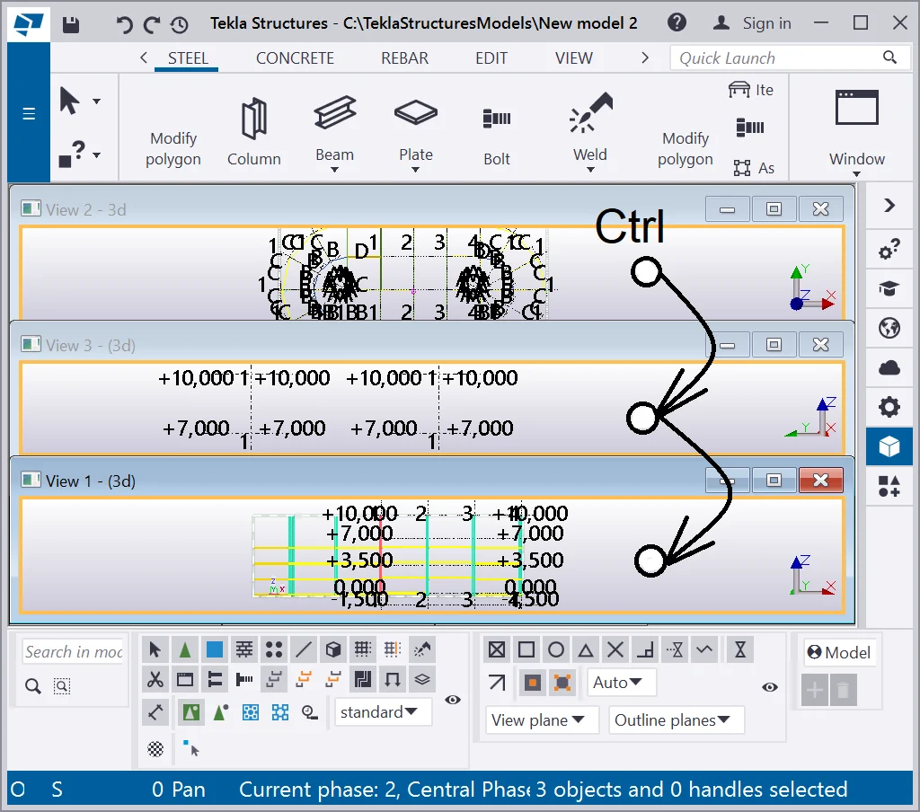
Unselecting the views is done similarly. Try it out.

Note that proceeding to the view plane by pressing the Ctrl+P hotkey combination
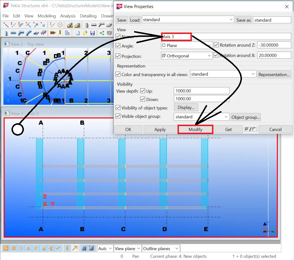
Go to the “View Properties” window by executing a double-click
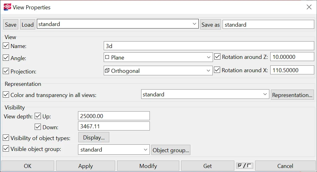
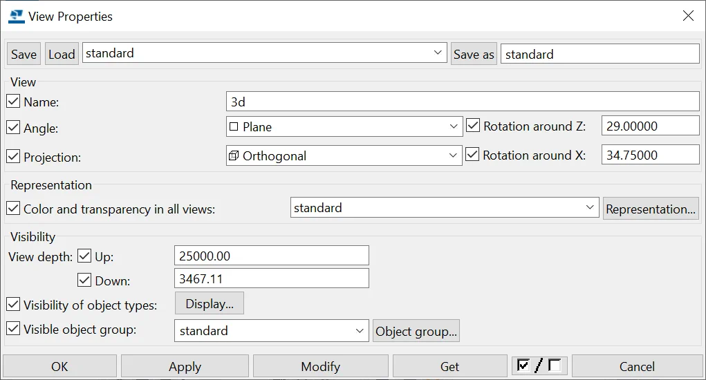
The “Name” field
The “Angle” field switches to the view plane and vice-versa. It correlates to the Ctrl+P hotkey combination functioning.
Rotation around the Z- axis
Rotation around X-axis -
The “View depth Up/Down” field
It indicates how far from the view plane the objects of the model are displayed. This means that each view created in the Tekla Structures is not infinite. Each view has its borders, and all the objects beyond the borders are not displayed. These borders are represented as a dashed line of a rectangle.

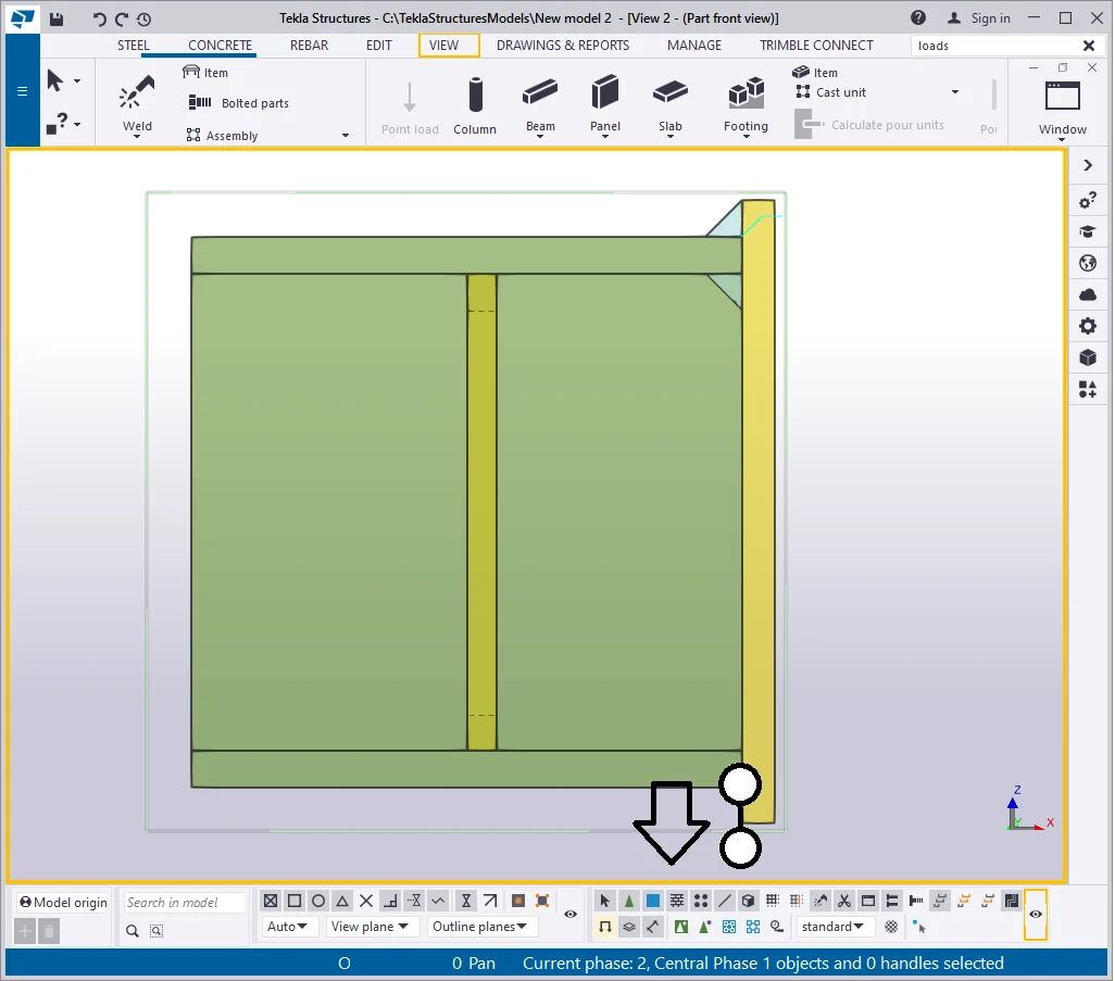
It is possible to create a view at an elevation point and to narrow the
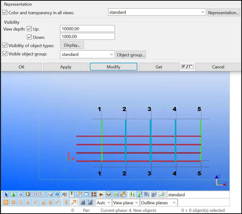
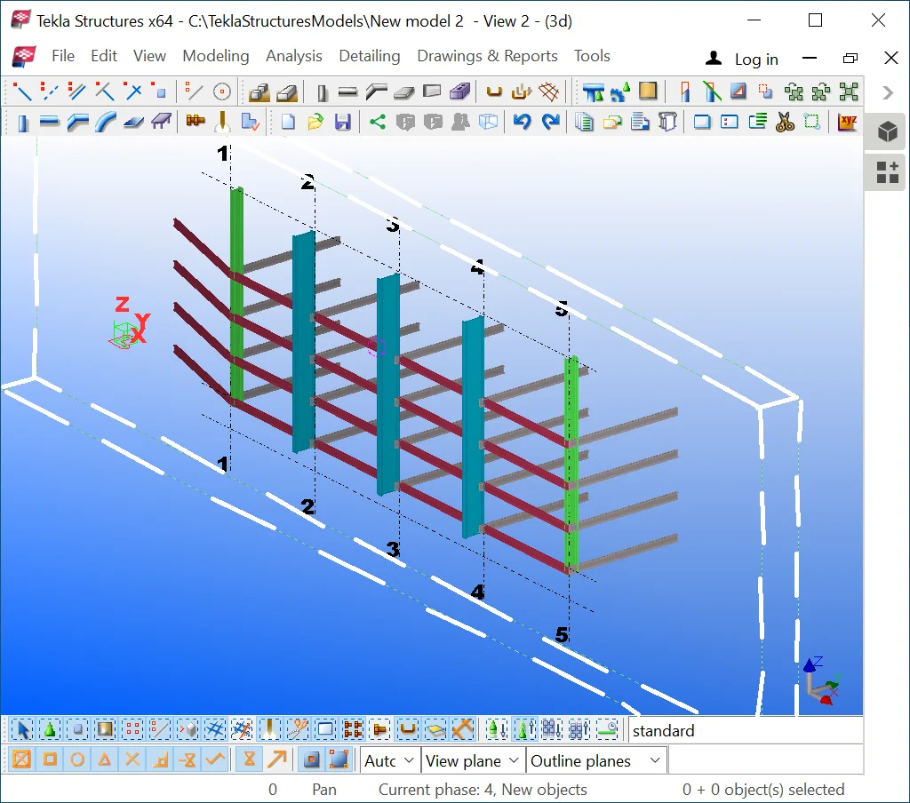
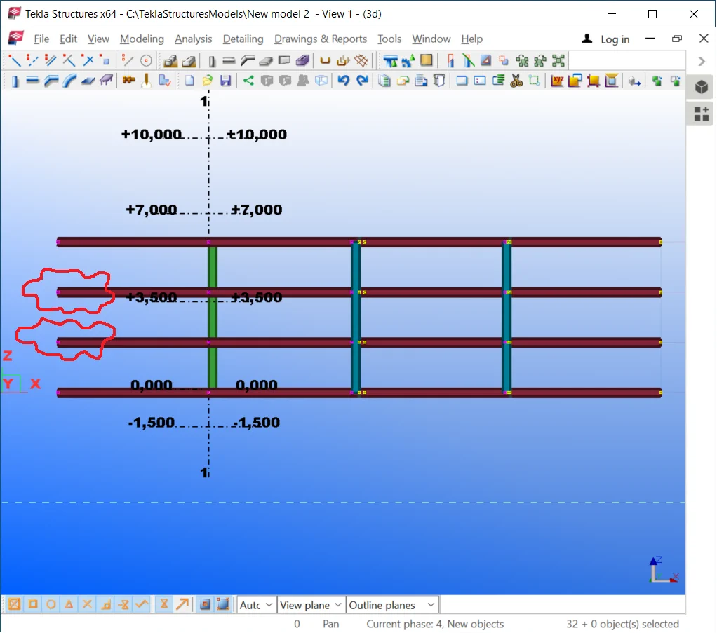
In the below view, you can see only the beams located at the -1000mm level, and every object which is located up to the 1000mm elevation. The following beamline of the +2000 mm elevation is not visible. The view depth affects columns differently, thus if at least a part of the column appertains to the view depth range, then the column will be entirely displayed. To see the second beamline, change the view depth value to 2000mm.
To entirely render the model specify the view depth value at 10000, this
The top view is the one created at the elevation point of +0.000 mm. When switching to the view plane, the view depth value indicates how many millimeters are in the direction from the screen towards the user.
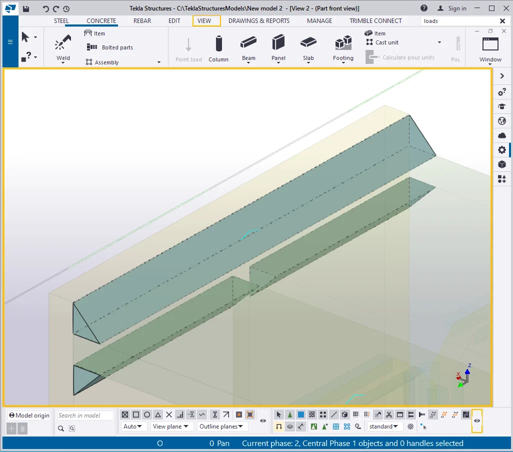
Open any of the side views. The view depth in the side views works in
To define in the right way where is the model top and where is the bottom,
Now we see the model at 1000 mm into the screen depth and at 1000mm towards

Thus in this view you can also see a limited part of the model.
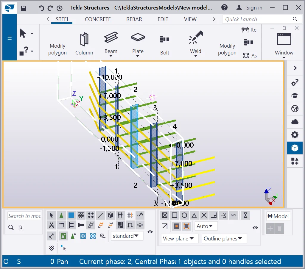
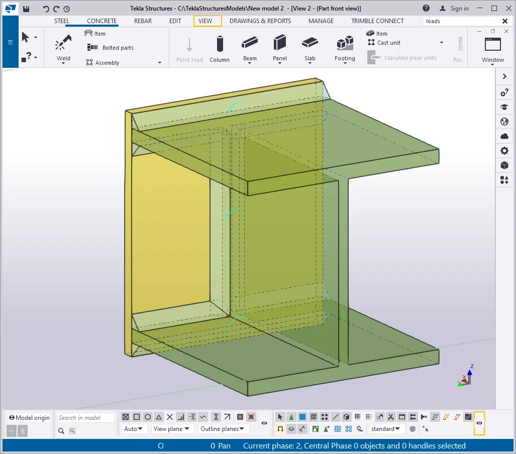
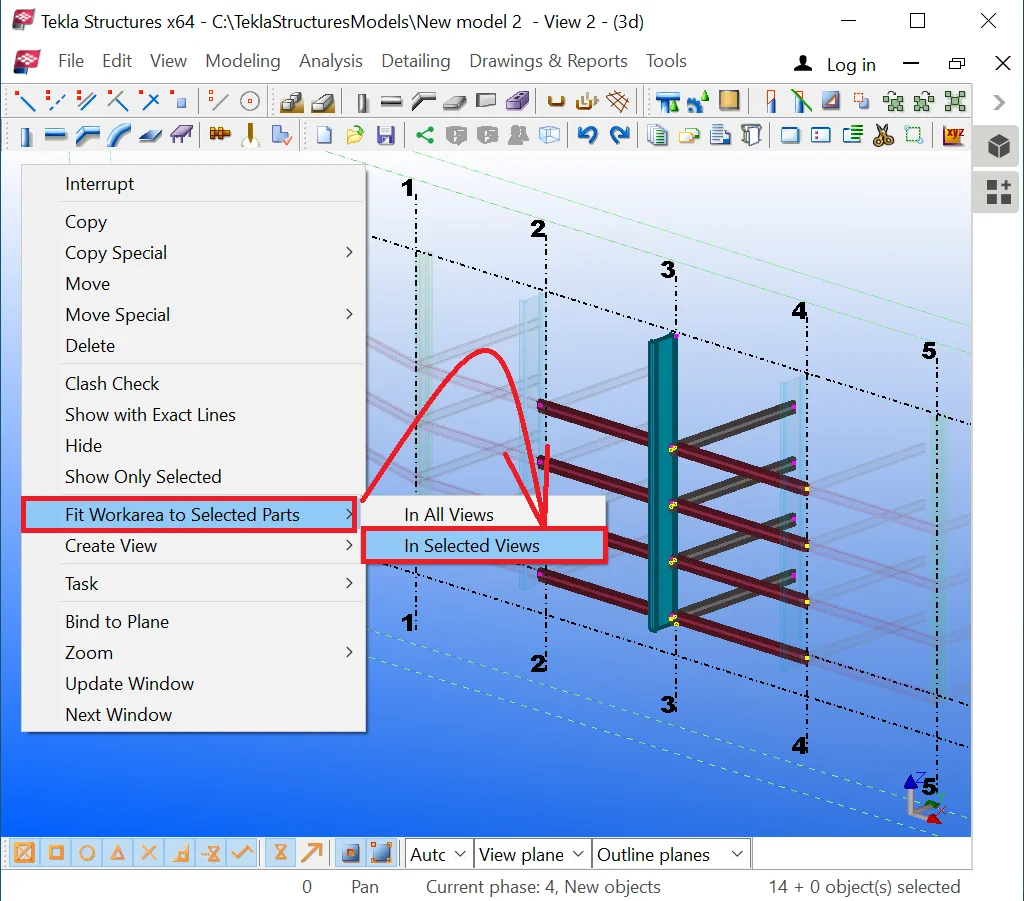
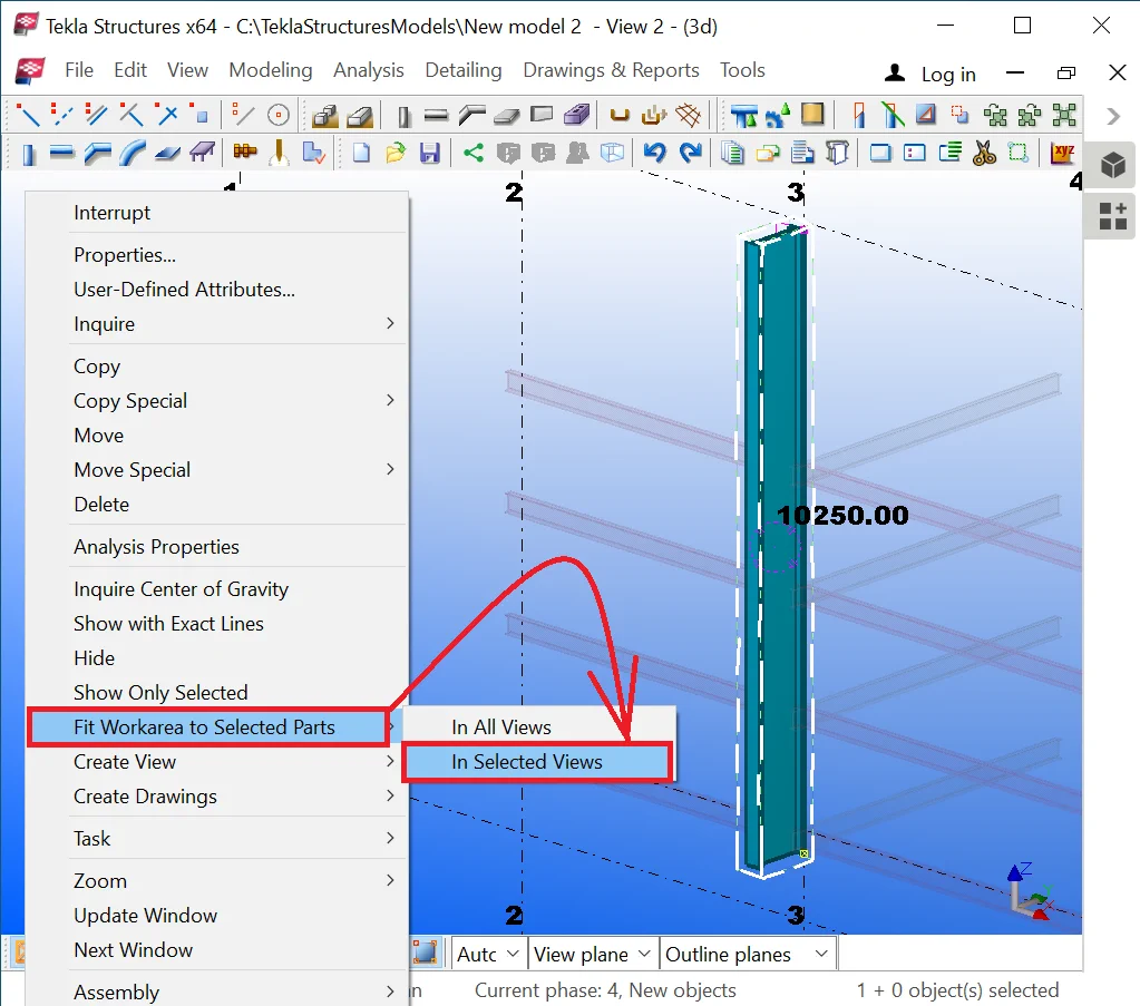
The workplane of a view is the volume of the structure enclosed between the dashed lines. The workplane borders are specified by the view depth parameters in the “Up” and “Down” fields although the shape of a work plane is constantly represented as a rectangle box. There is no special tool for narrowing the side view of the workplane. In this case, it comes in handy just simply selecting the required objects and enabling in the right-click menu the “Fit work area to selected parts” in the “Selected views” tab.
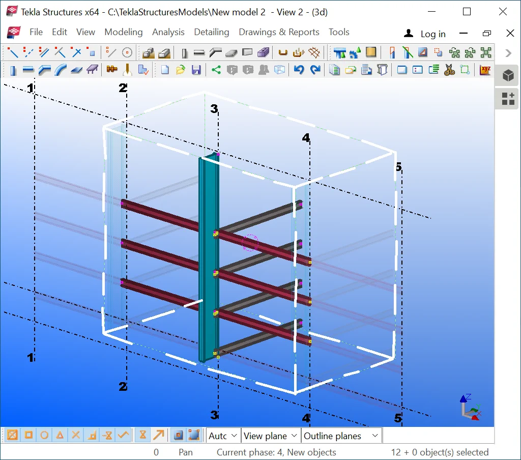
Note that now only the selected objects are visible in the view.
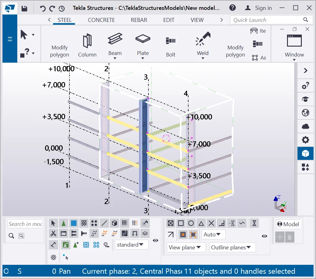
Select a column and fit the work area to the selected part in the current

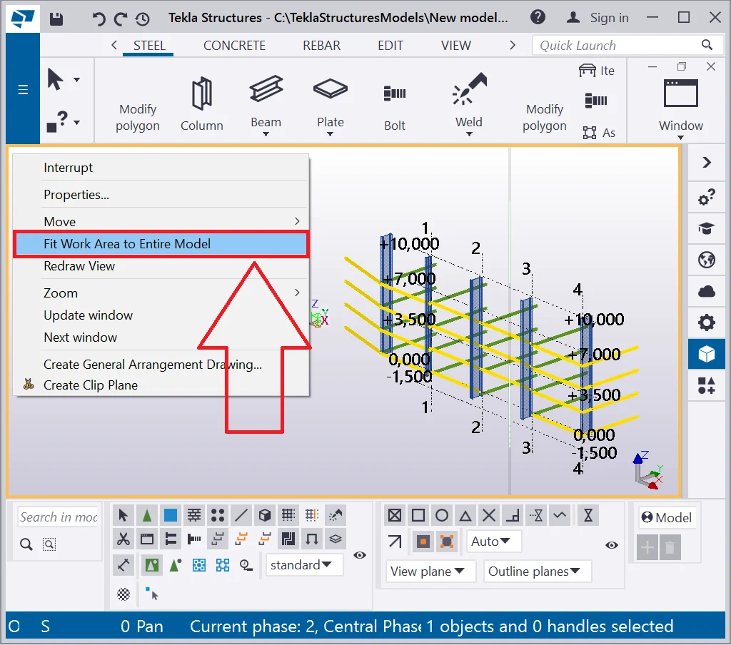
To restore the view, access the respective tab in the right-click menu,
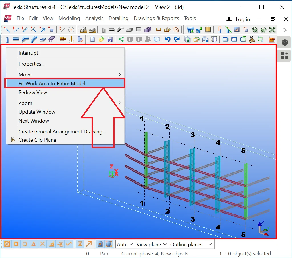
The TS will widen the visual borders of the work plane to the right, left, upwards, and downwards, but will not modify the view depth value which is outlined by the dashed line, this being the situation not corresponding to reality, as the factual work plane borders can not ignore the view depth parameter value.
Only after indicating the view depth values into the respective field


The view depth value is defined in the “View Properties” window. It is possible to indicate the “Up” and “Down” fields values with negative characters.
Try out setting up various values of the view depth as well as fitting to the workplane area several selected parts. It is important to understand the functionality of this tool as it is a very frequently used one.
The "Projection" field switches the view from the Orthogonal regime to the Prospective one. It is not recommended to be used in practice as it tampers with the model pattern. The prospective view is useful when presenting a model. Set up the view depth parameter value at 10000mm at the orthogonal regime.
Now switch the Orthogonal regime to Prospective. Thus the same object

Rotate the model. Upon completion, restore the "View properties"
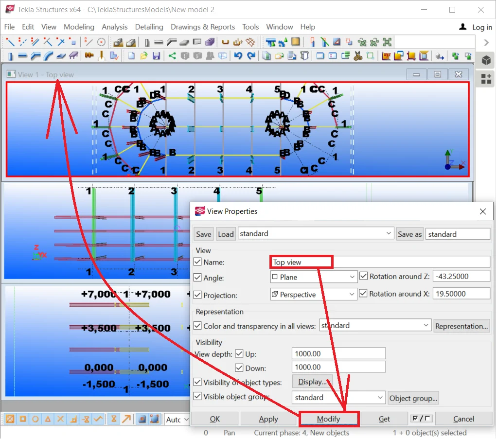
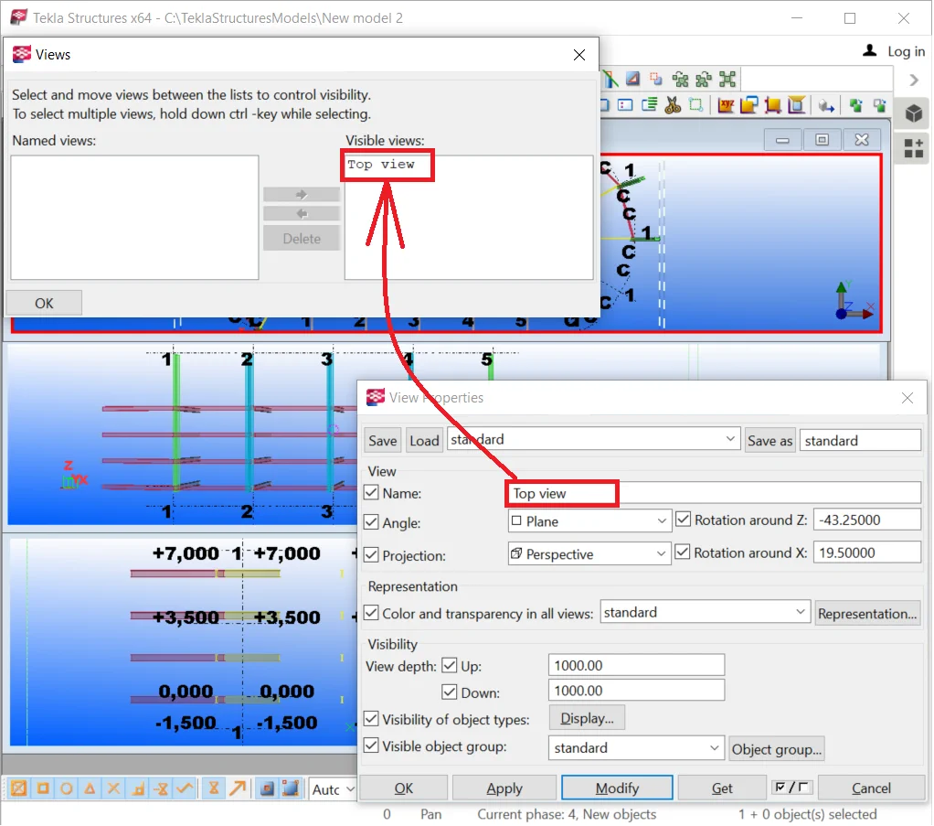
Go to the “View list” by pressing the Ctrl+I hotkey combination, and see the list of all the views created. If a view name is enclosed in round brackets, then this view is considered a temporary one. Delete the current name of the view, remove parentheses and write in its new title as “Top view”.
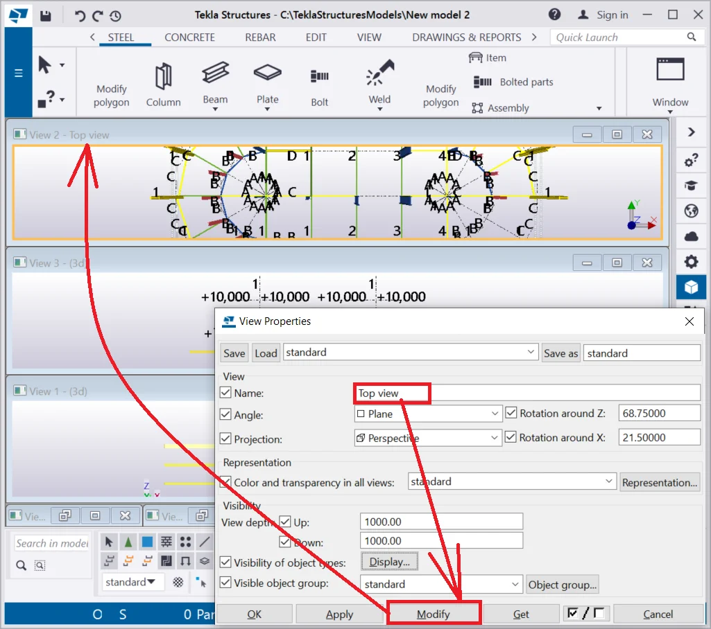
Now, when opening the view list (by pressing the Ctrl+I hotkey combination) you can see the “Top view” title among the others. Now, when closing the “Top view” window, it can be easily restored by double-clicking on its title in the view list.

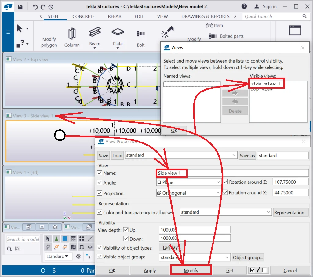
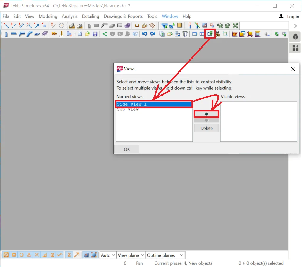
Save the following view as “Side view 1” by opening the view properties window and writing the respective title into the respective field. Refer to the below:
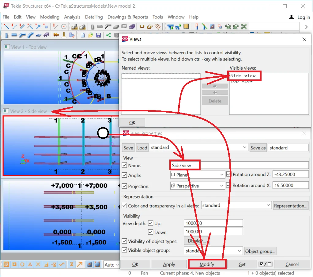
Save the following view as “Side view 2” by using the following algorithm: do not close the “View properties” window, select the view required, in the automatically updated “View properties” window write the view title into the “Name” field and press the “Modify” button.

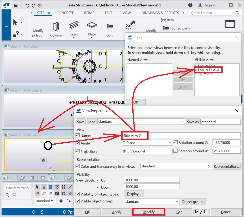
Note that enclosing the view title into round brackets, automatically makes it a temporary one, which means it will not get registered into the view list, and in case of any accidental closing of the view window, the view will no longer be available. Rename the “Side view 2” to “(Side view 2)”.
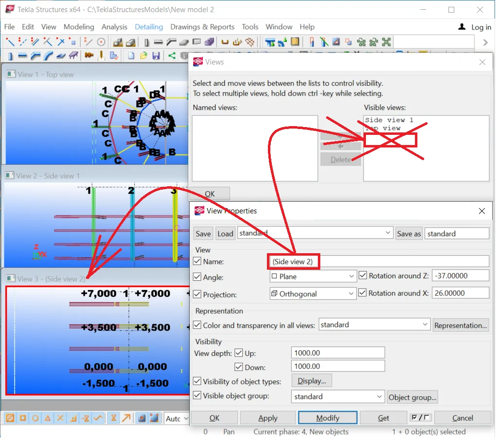

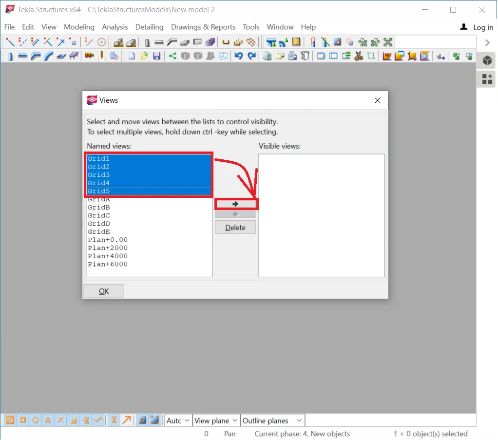
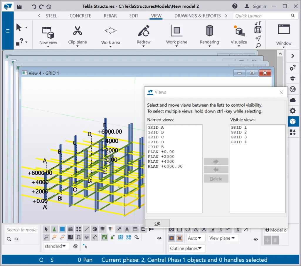
Close the view list and all the views open.
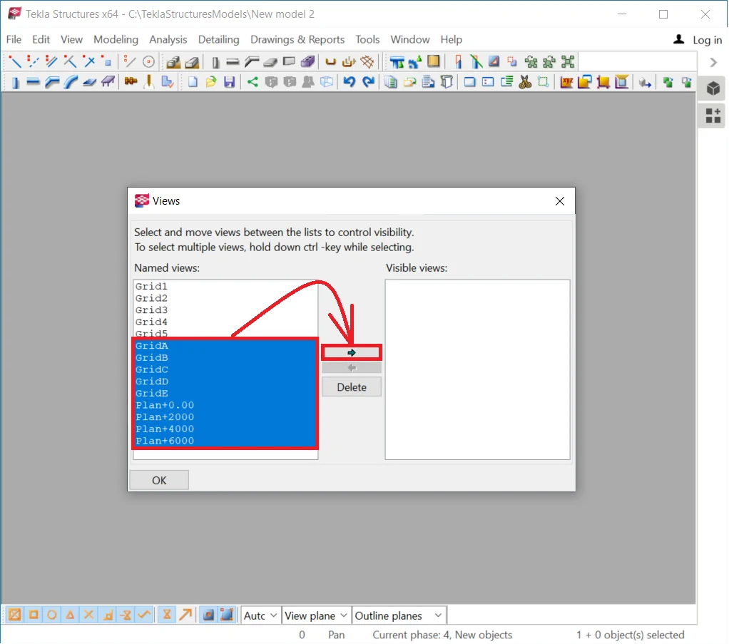
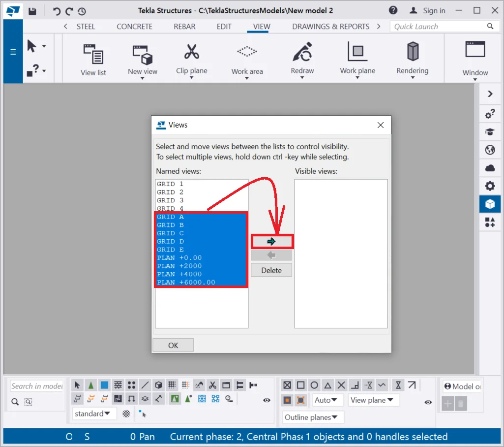
By pressing the Ctrl+I hotkey combination, go to the view list. Select a view from the list, and by pressing the “arrow” button transfer it to the visible views column.
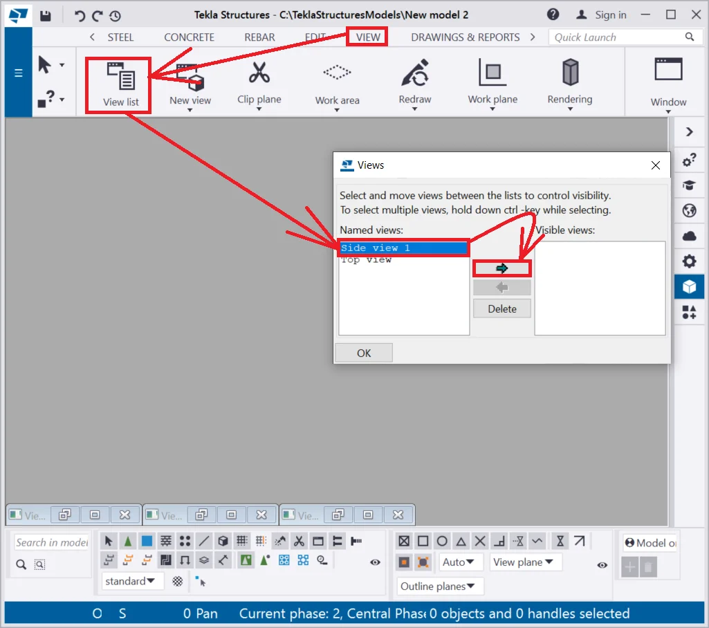
Also, pressing the "Arrow" button opens the view window and allocates it to the work area. It is possible to open any view by double-click on its title in the view list.
Try out this way as well.
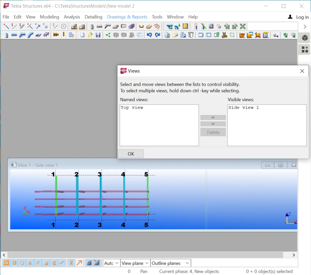
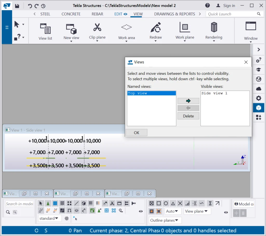
The second view was restored similarly.
Till now, we have studied how to create three basic views, which certainly are not enough for operating in full. Thus TS is available on many other tools for creating various views.
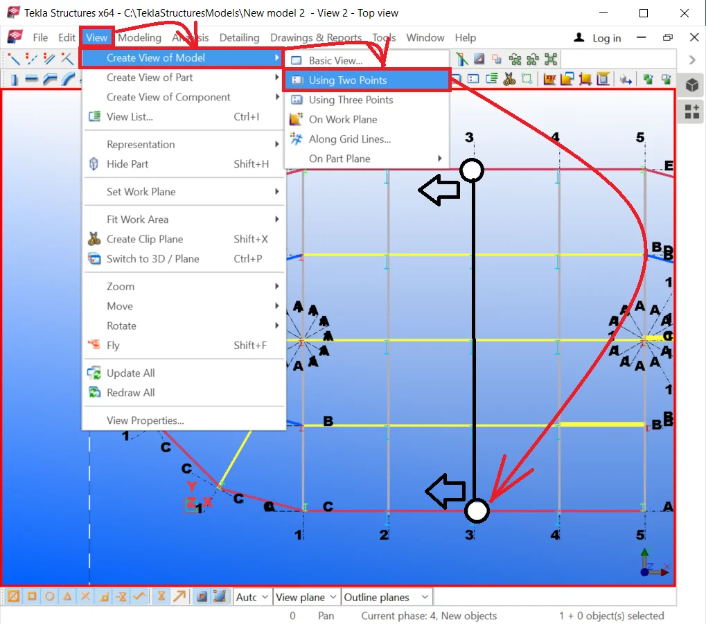
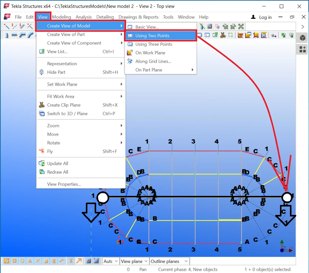
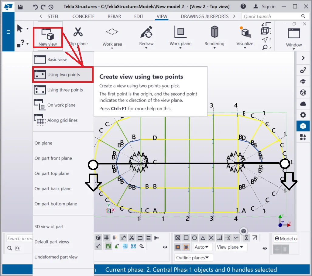
Let's explore all the possible ways for creating the views by accessing

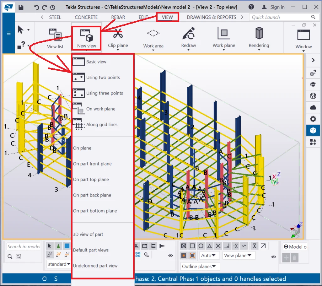
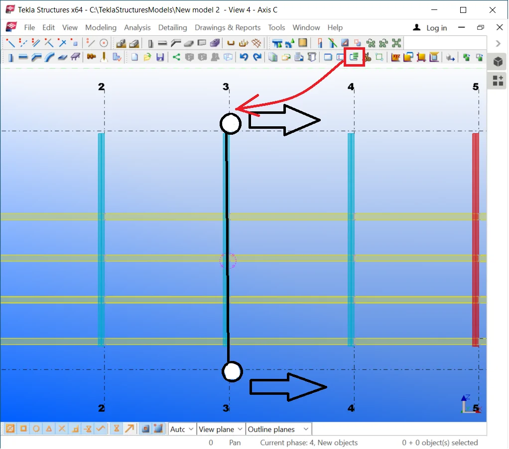
Create a view by “Using two points” tool creates a view by indicating 2 points, thus the newly created view is perpendicular to the initial one.
The algorithm for managing the create view “Using two points”
Let's try out applying the above algorithm, thus go to the "Top
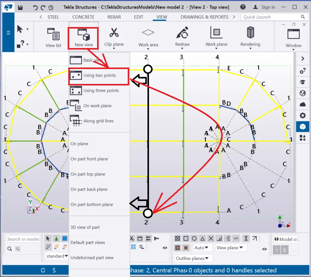
Rename the view as “Axis 3”.
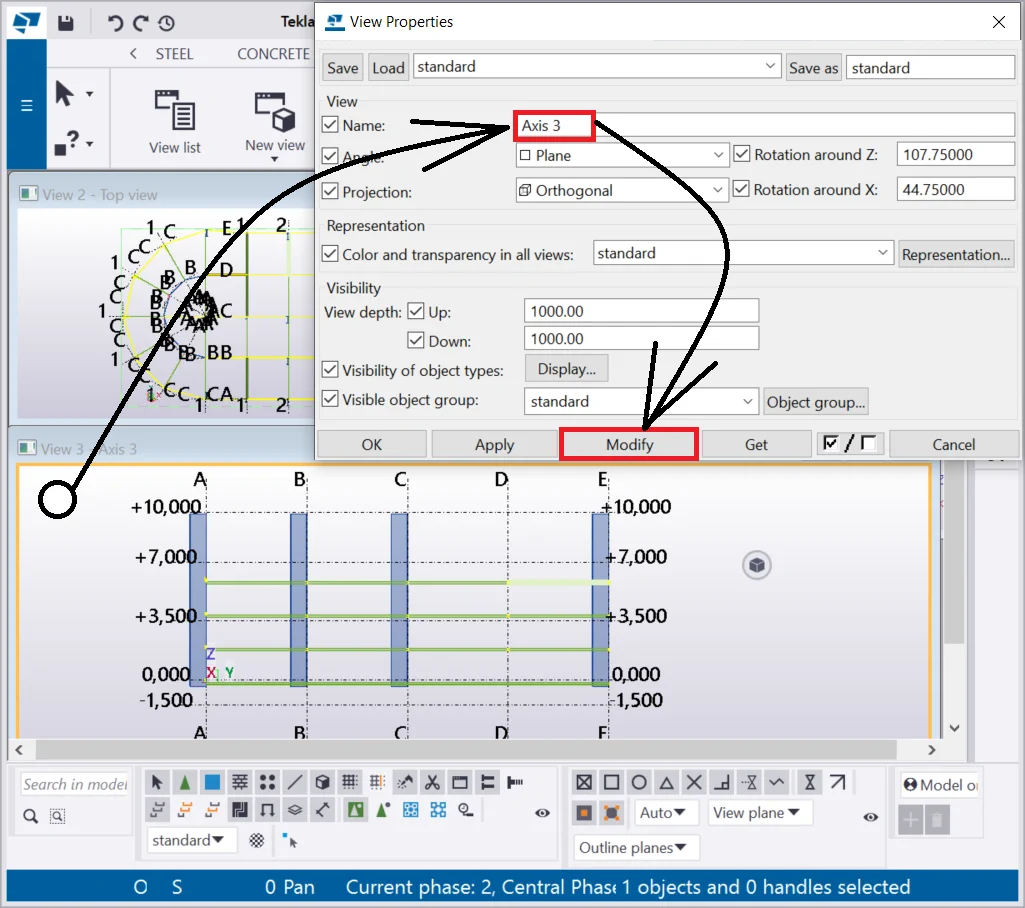
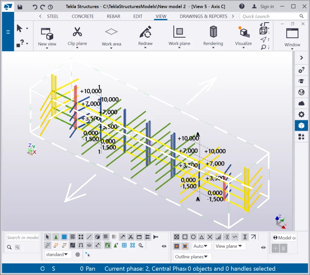
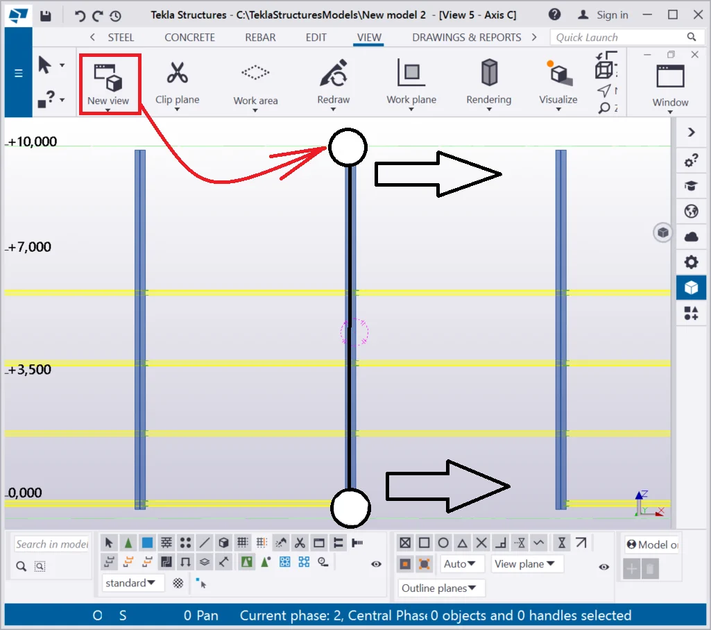
Also, let’s create a view along with the axial tilt as it is shown below. The points indicated are forming the plane border, from which the view depth (Up/Down) is to be set out.
If the view depth is not of a considerable value, then we will see only
Set out the view name as “Axis C”.
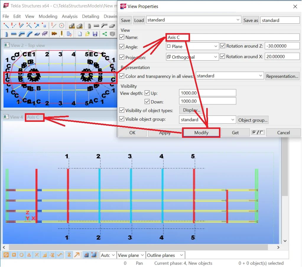
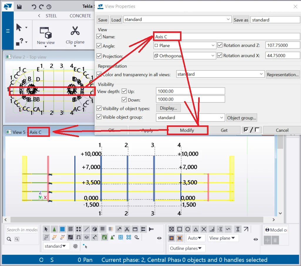
Note that each view has its own view depth parameter value, thus when creating an axial view we define only the beams located at the axis selected.
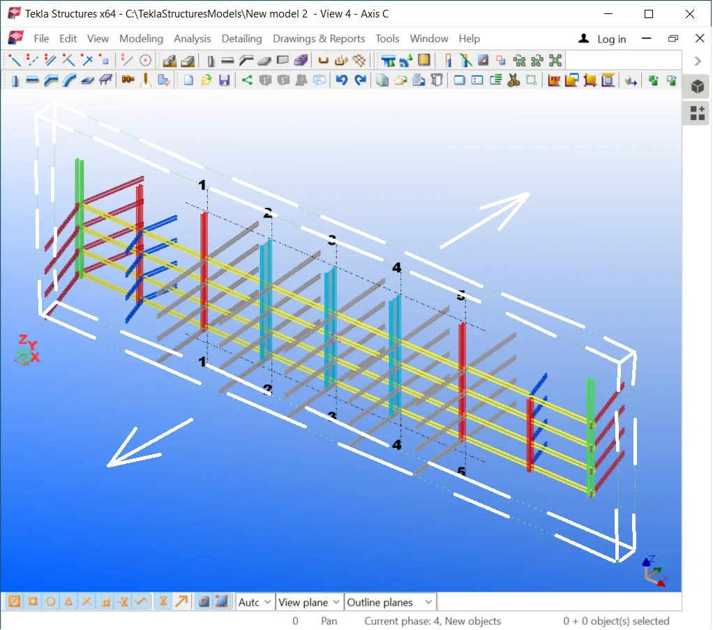
Also, it is important to remember that the new view created is every time perpendicular to the initial view. The reason for this is that defining a plane requires 3 points, but we use only two and the TS automatically sources additional coordinates.
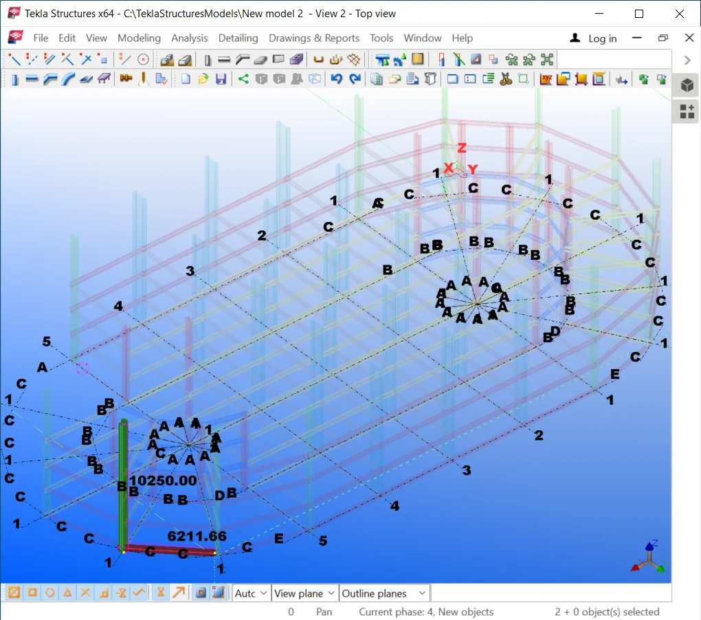
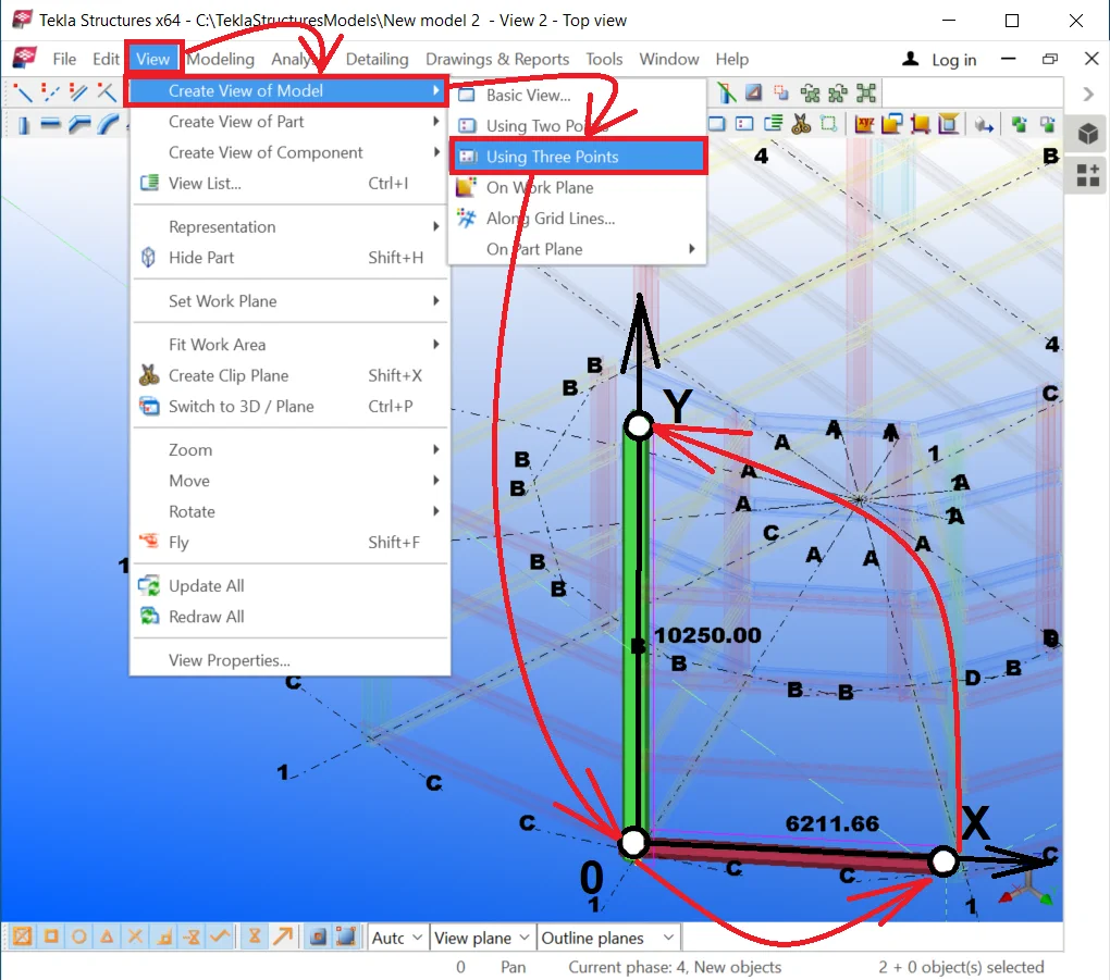
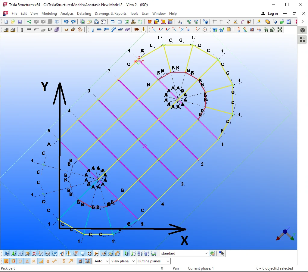
It is also possible to create a 3D view, thus enable the “Create view - Using three points” tool. Let’s try out creating a cross-sectional view along axis 3.
It is important to understand that all the views created by this method
If the gaze direction does not coincide with the described above then
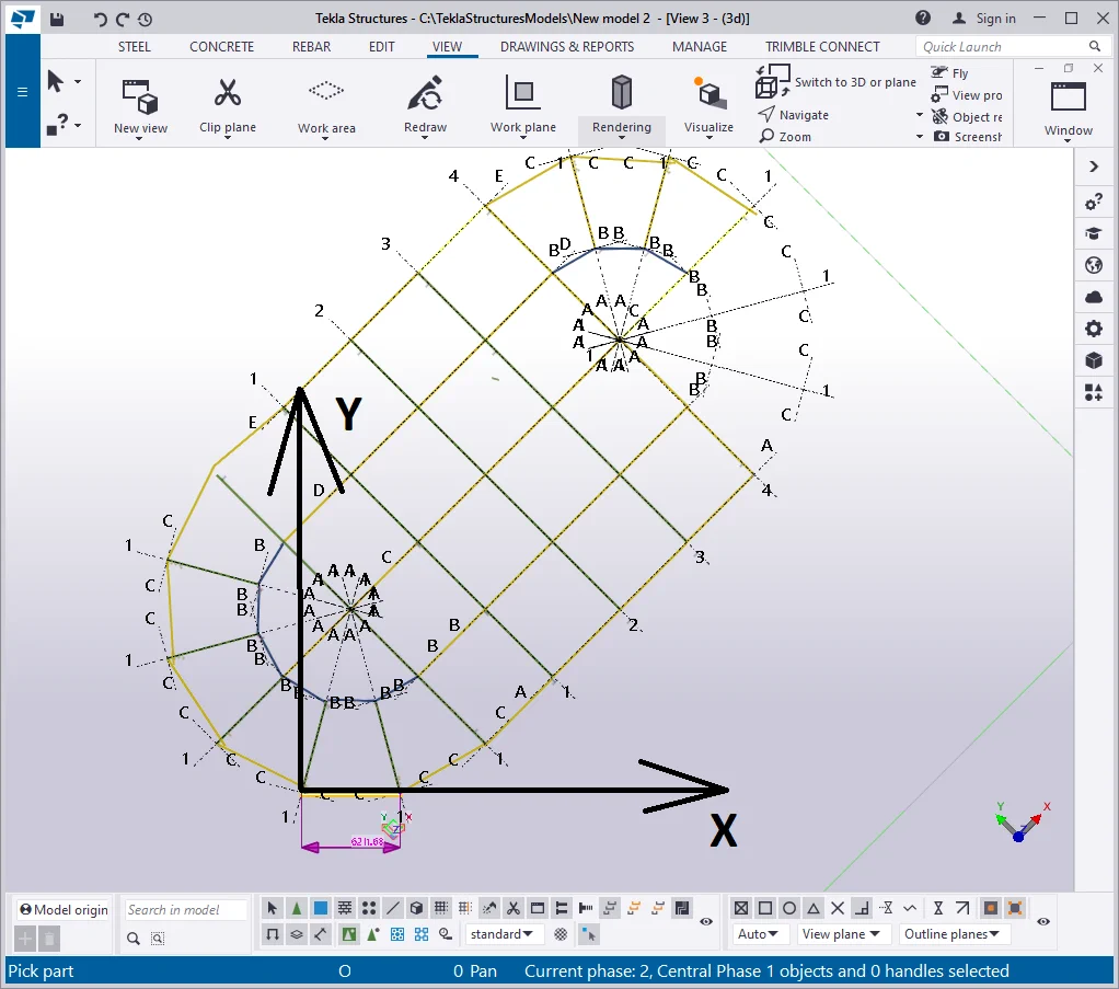
In the above picture, you can see that the structure is laying on its side. The points indicated are forming the X-axis which is parallel to the user's gaze direction.
Thus creating a view using 2 points should be done based on the top view
Tekla Structures v21.1 |
Tekla Structures v2021 |
|
|
|
For creating complex views or views requiring cognizance of the axes'
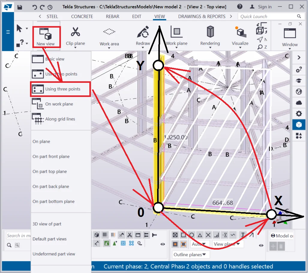
The Create a view by “Using three points” tool creates a view plain, which is defined by 3 points thus the output view can be inclined to various angles. It is mostly practiced when modeling complex roofing with directional slopes.
Select a column and a beam and set the display mode to Ctrl+5.
Now let’s create a facade view along the selected beam.
The algorithm for managing the create view “Using three points”
Do not confuse the axes, as switching to the view plain by pressing the Ctrl+P hotkey combination aligns the X-axis horizontally. If you do any tangling between axes, the new view will spin around, making it difficult to work with the structure.
Create a view “On work plane” tool sets up a view of the current work plane using the current properties reflected in the "View Properties" dialog box. It does not require specifying any coordinates or selecting any objects, as these are copied from the coordinate system of the work plane. Close all the views and proceed as it is shown below:
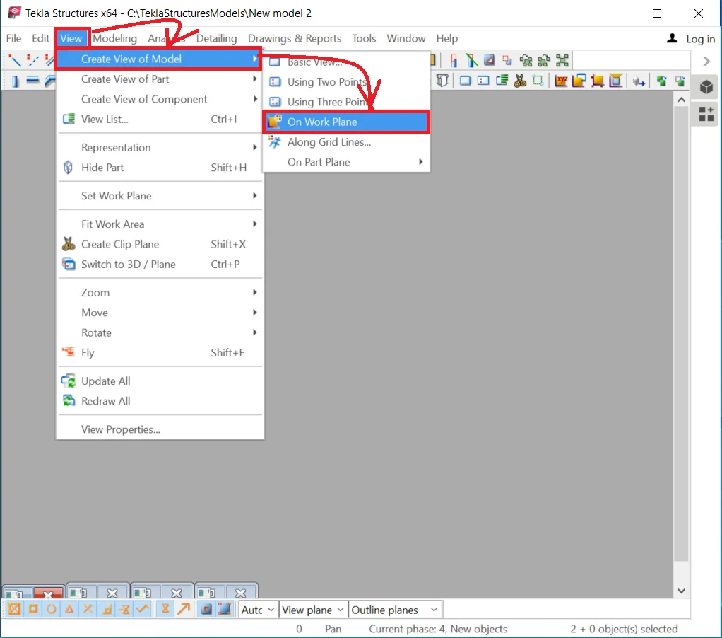

Thus the new view was created at the same plane as the work plane is.

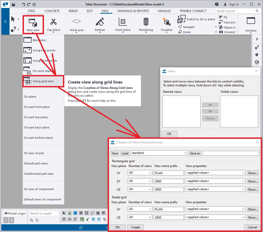
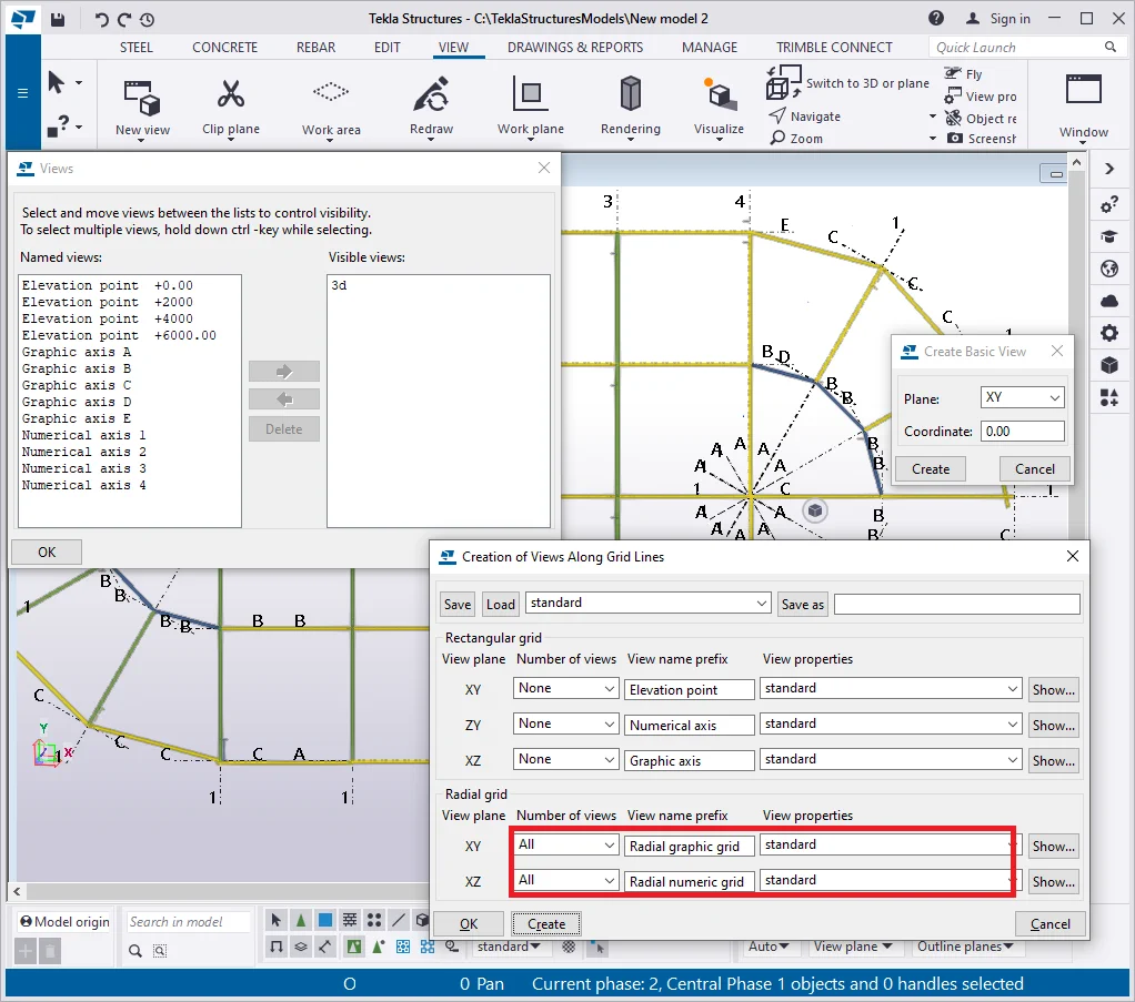
Create a view “Along grid lines” tool creates views concerning the grid lines and elevation points, thus allowing creating a vast variety of views. It is one of the most frequently used tools.
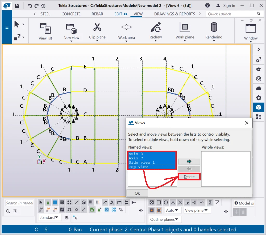
Delete all the views from the view list.

Create a top view and go to the Grid Properties menu. Check if the leveling points of the beams coincide with the respective of the grid. Check on the result by getting into any side view.
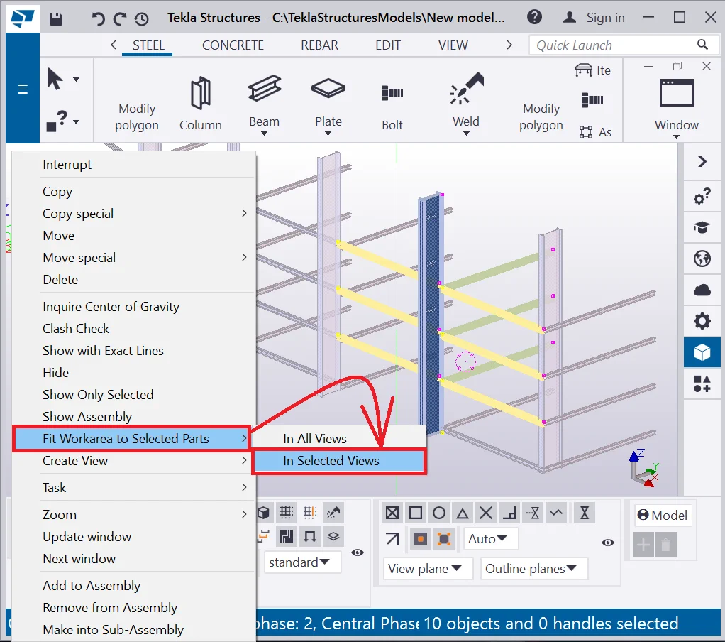
Select any column at axis 3 and the beams adjacent to it by framing them.
In the right-click menu select the “Fit work area to selected parts - In selected views” tab to avoid viewing the round parts of the building.


Make sure all the elevation marks are set up at the grid properties menu,

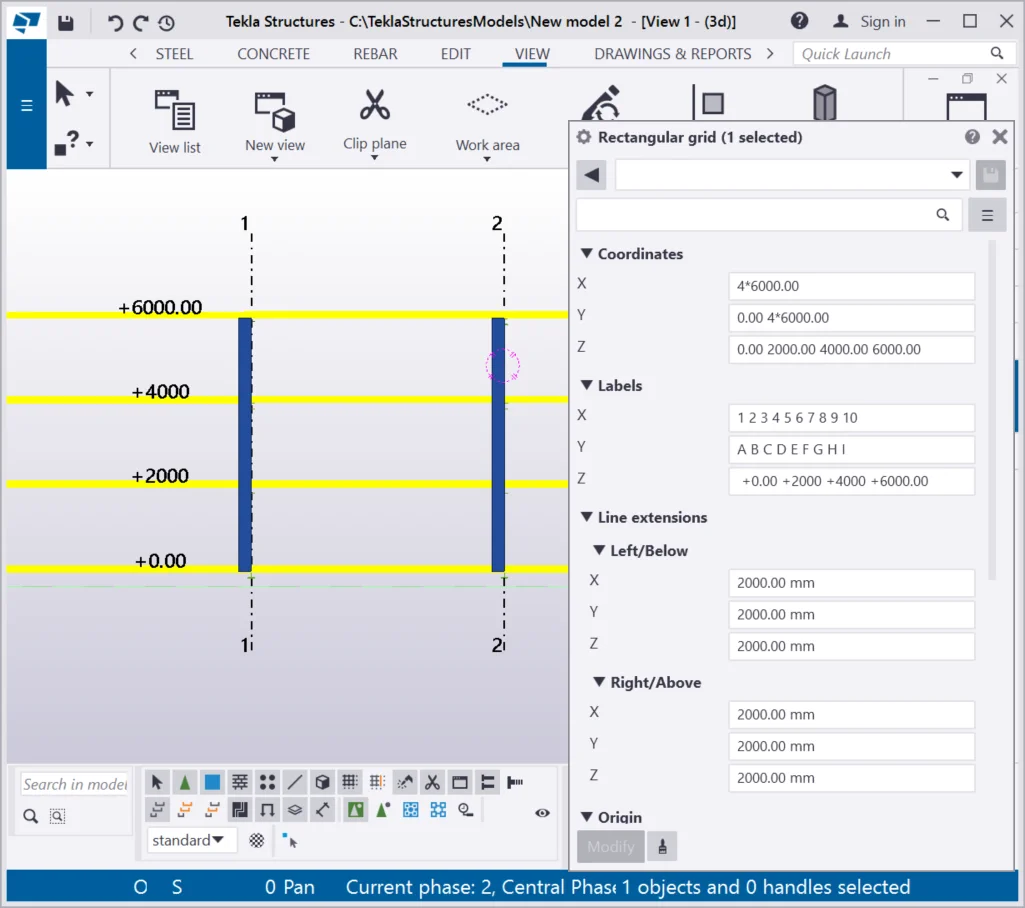
Go to the “Grid Properties” window and edit the "Labels" field. Do not forget that the 0 value is a constant one and shall not be removed.

Real models do not require any grids setting up.
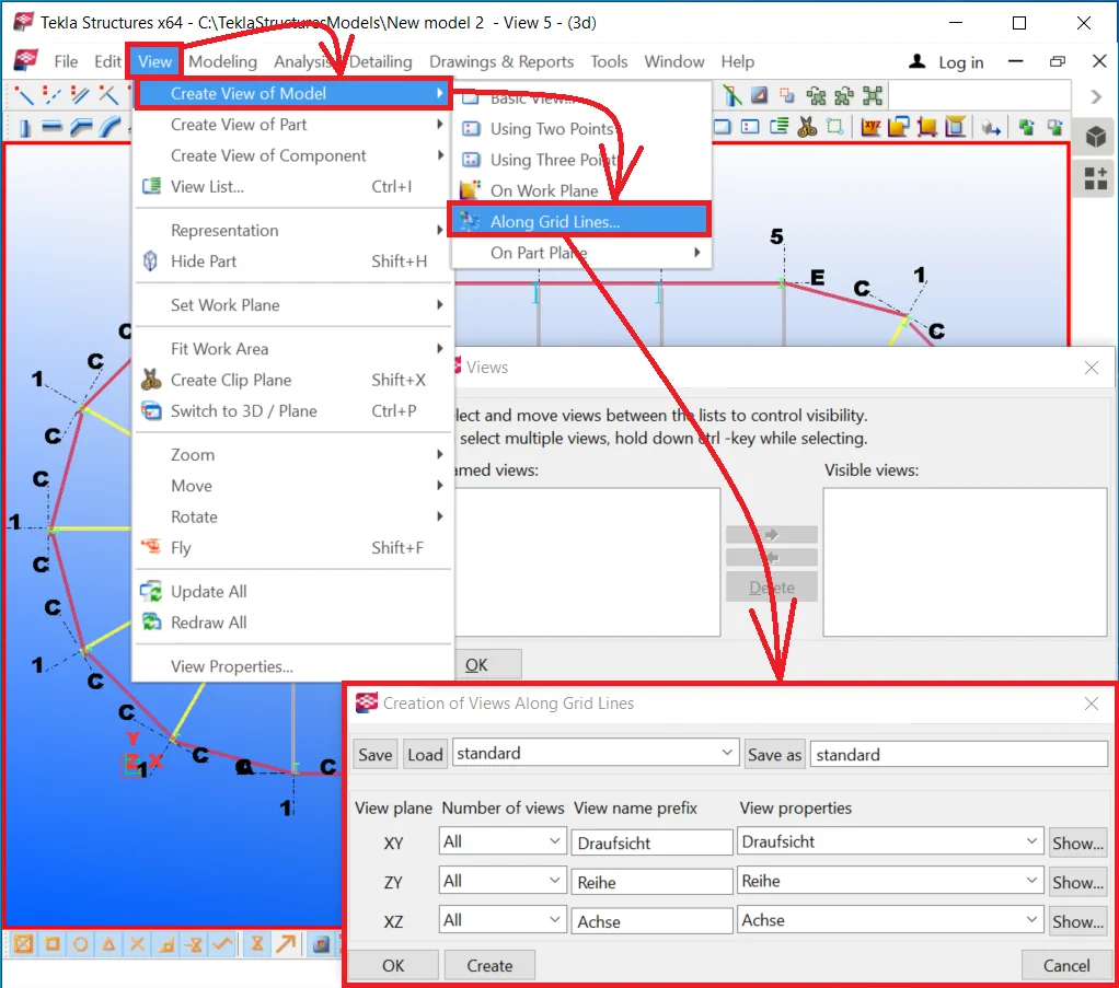
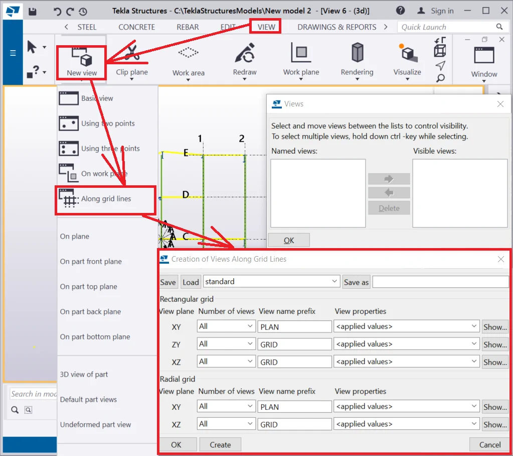
The algorithm for managing the create view “Along grid lines”
Check the views created. When configuring parameters at the “Create
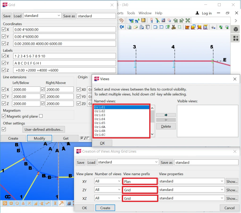
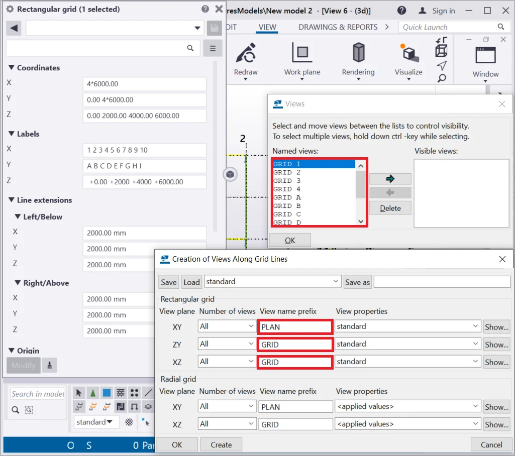
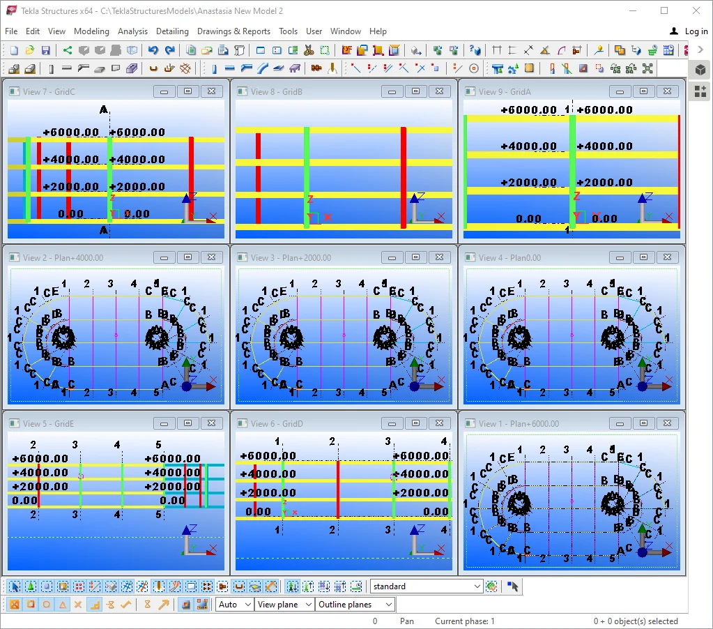
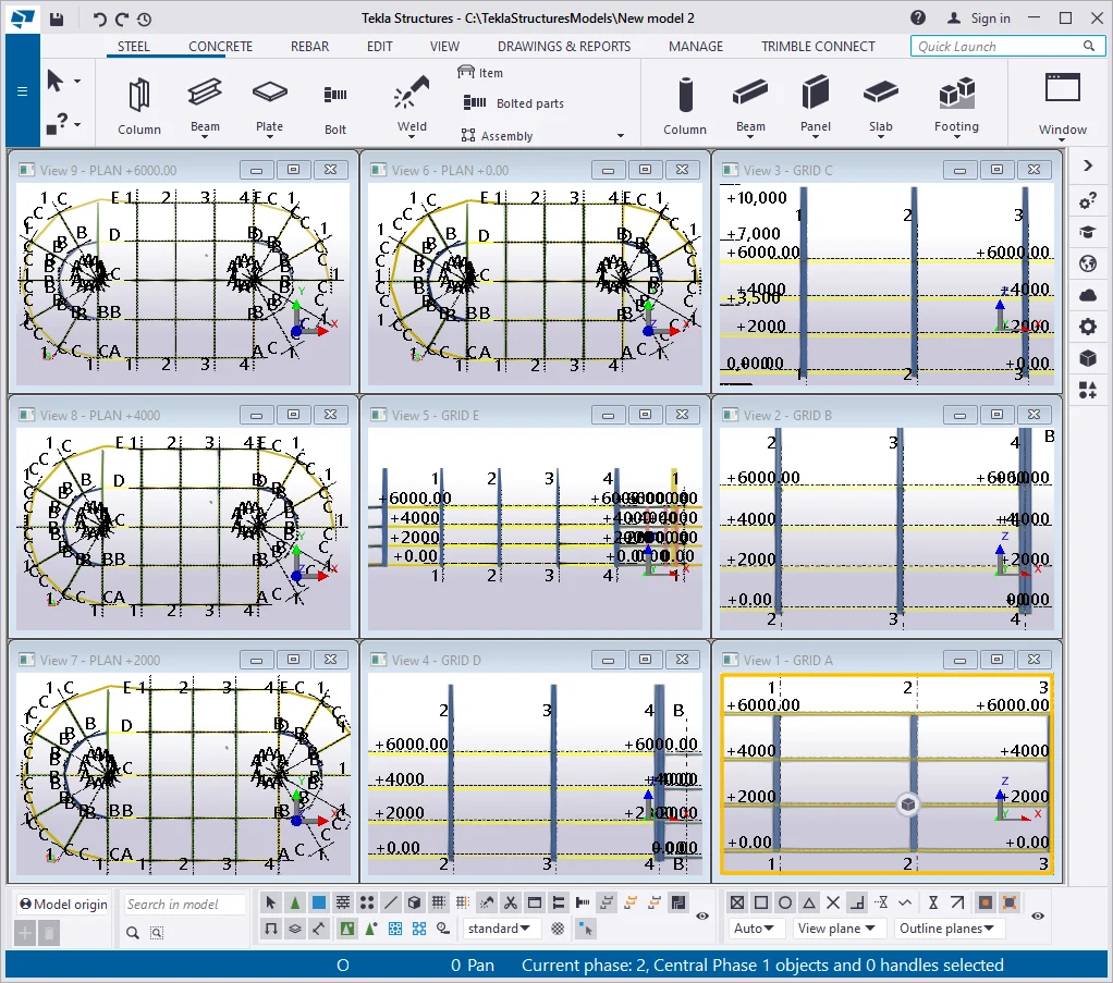
The views were automatically created along the selected grid lines as well as the elevation points views. You can easily navigate and work in the views, keeping with the purposes of your project.
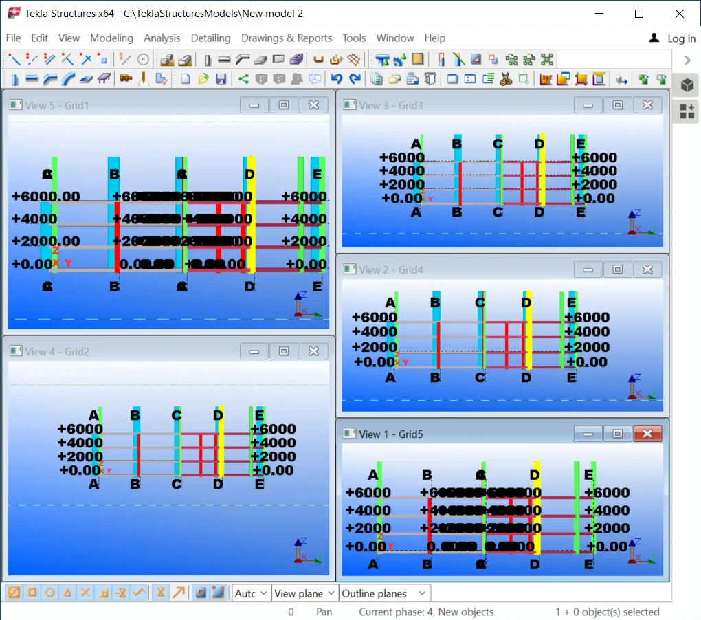
Close all the views and at the “Views list" select the ones

Arrange the views horizontally.

The views opened refer to the numerical axes of the model.
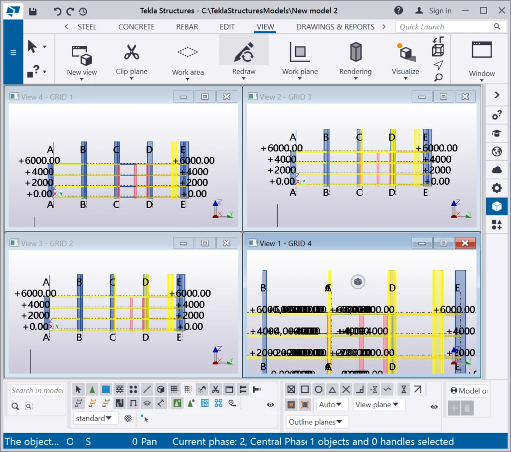
In TS it is possible to simultaneously open only nine views. Thus close
Arrange the views horizontally.
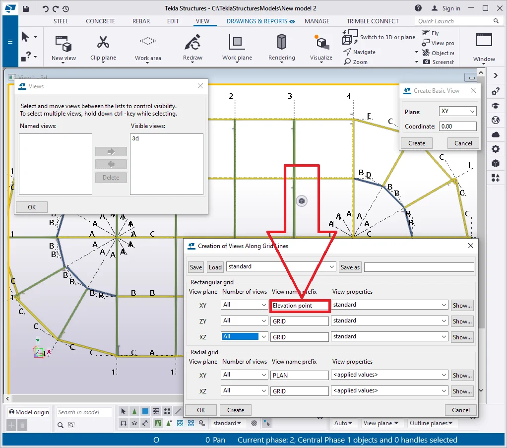
Delete all the views, and create a basic one and repeatedly enable the

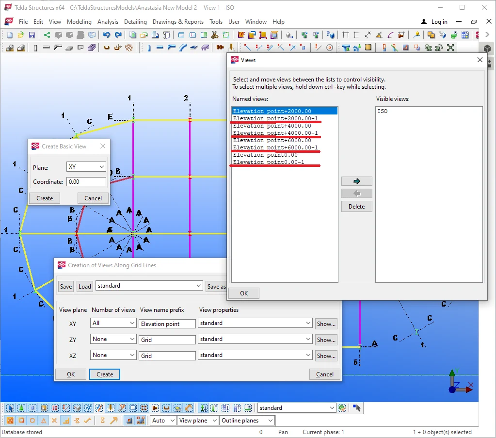
Set the “View name prefix” as “Elevation point ”. Make sure you leave a space after the textual specification of the view’s title.
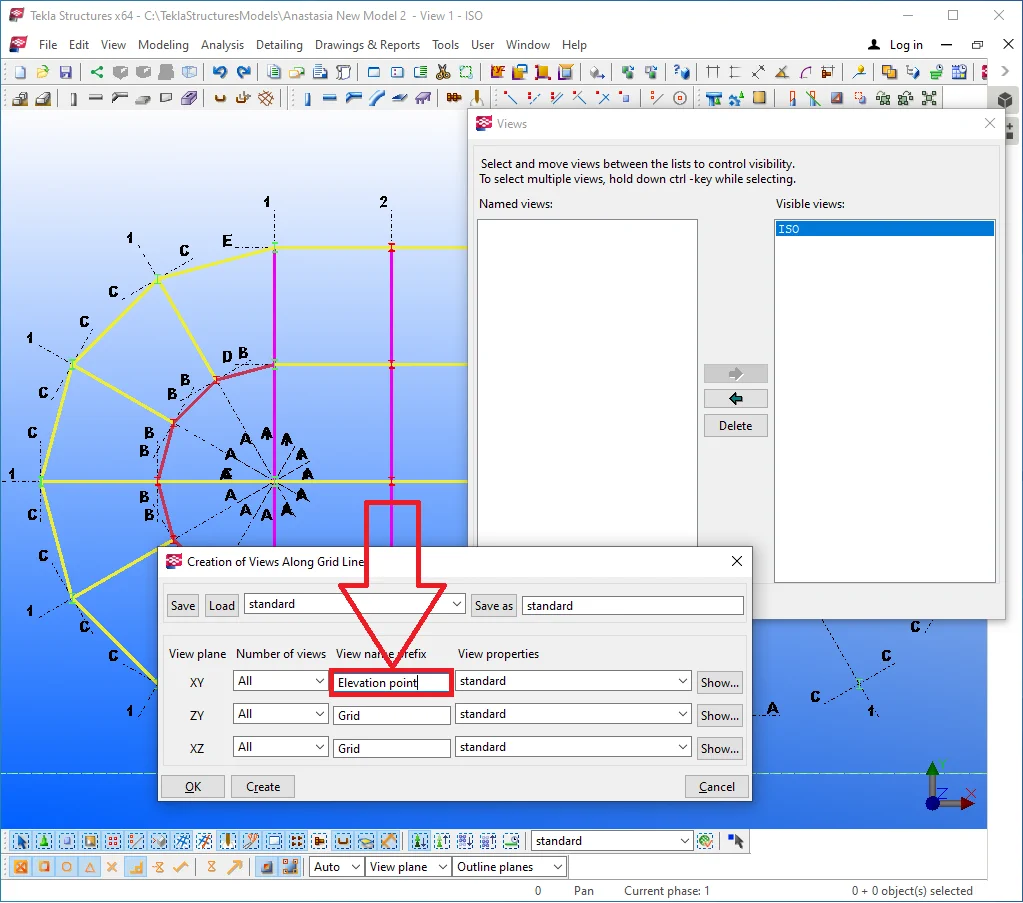
Then, deactivate the fields for creating views ZY and XZ. Press the “Create” button. Do not forget to select a grid before exercising the above. In the current case study let's select the basic grid of the building.
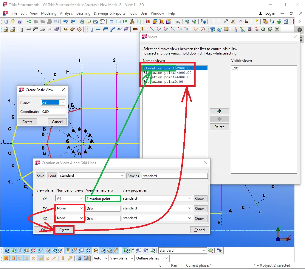
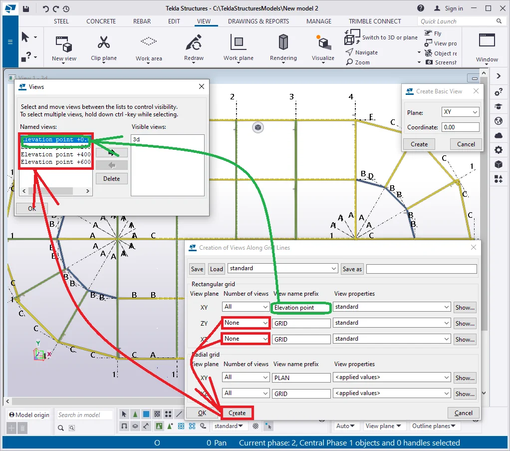
Repeatedly press the “Create” button in the “Create Views Along Grid Lines'' window. Note, that TS created duplicates of the views with the “-1” side mark to the title line.

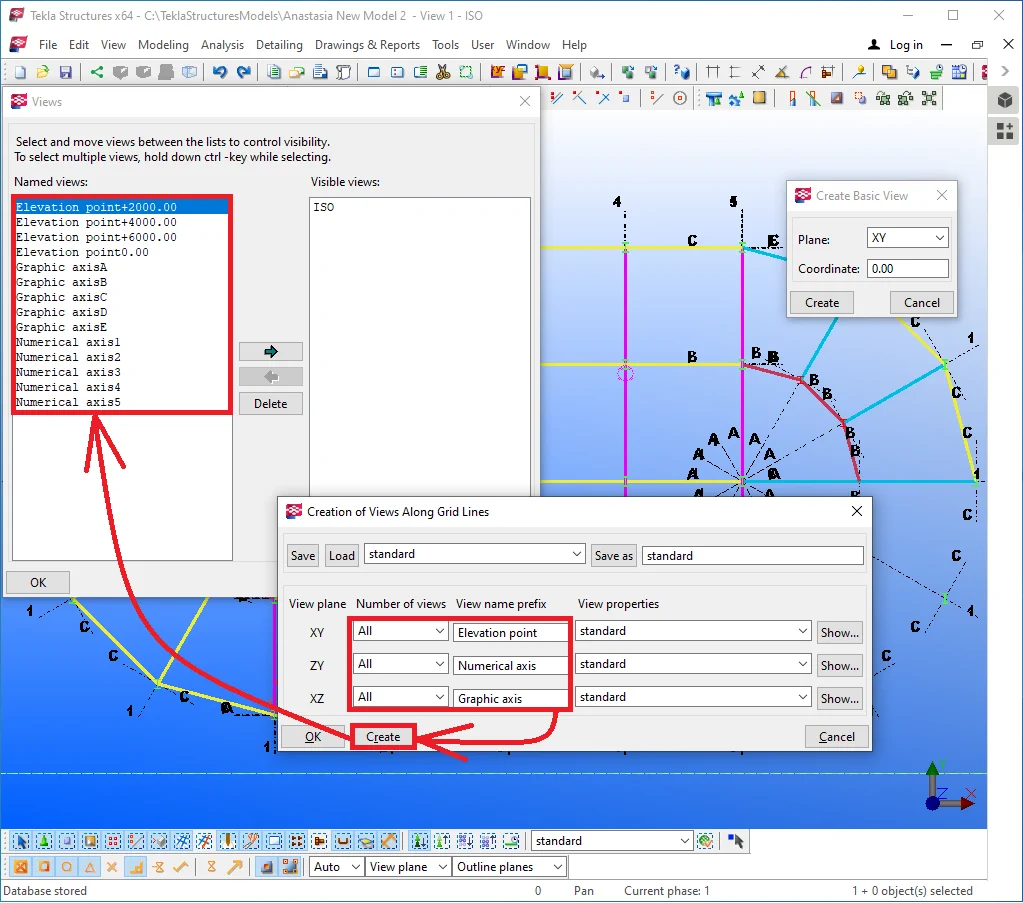
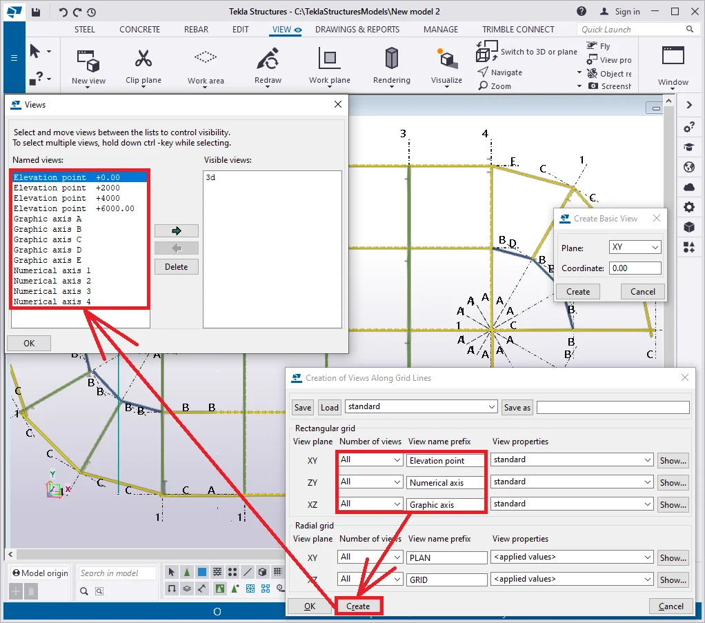
Delete all the views, and activate the ZY, XZ fields and specify accordingly the view name prefixes as follows: ZY = “Numerical axis ”, XZ=” Graphic axis”. Do not forget to use the space character at the end of each title string.
Let’s also examine creating radial grids.
Select the radial grid and set out its name as “Radial graphic grid”. There is no major difference between creating radial grids and the standard ones, except for the fact that radial grids are not created along the radial lines.
Try out yourself creating various cuts.
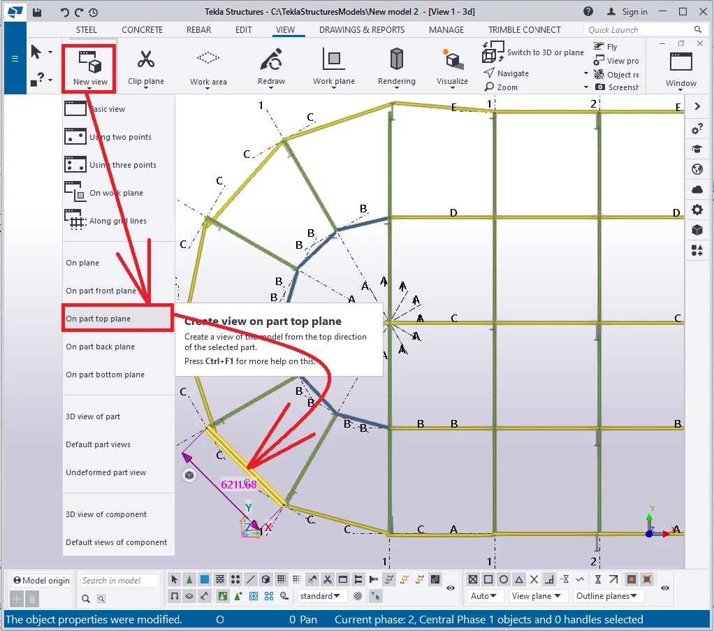
The “Create view on part plane” tool creates a view of a part in the selected plane. The part’s plane is determined by its local coordinate system.
Try out applying this tool by closing all the windows except for the top view. Thus go to the "Create view" drop-down menu and proceed as it is shown below:
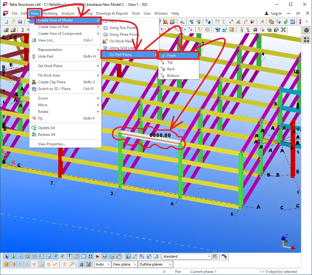

The view is created along the selected beam and is not dependent on any


Close the new view, re-enable the tool and select a beam located at an angle to other structural elements. Thus the X-axis of the new plane will coincide with the X-axis of the beam, and the new view will be defined by the local coordinates of the beam.
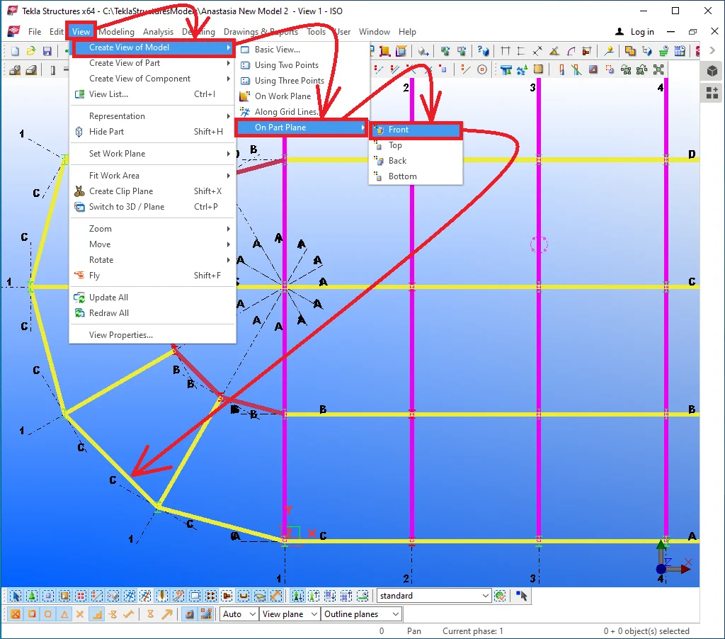

As you can see the beam's "Front view" is similar to the
Other view types are created based on a similar logic and use the beam's
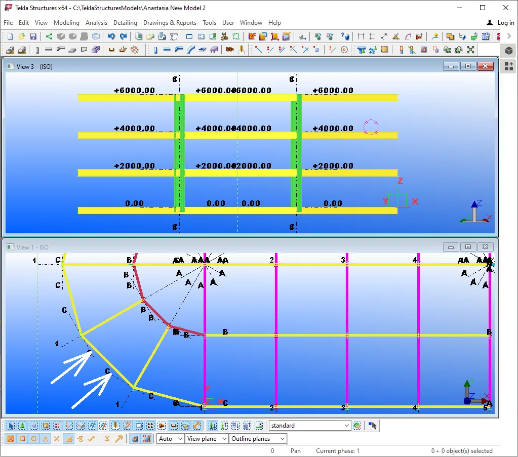
Try out creating the parts top plane, with the view coordinates direction

The view is codirectional with the beam's coordinates.
This tool is not of frequent use as the views created are inclined at
Examine by yourself features of the “Create view on part backplane”
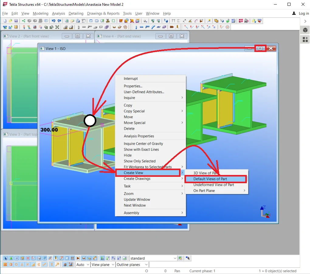
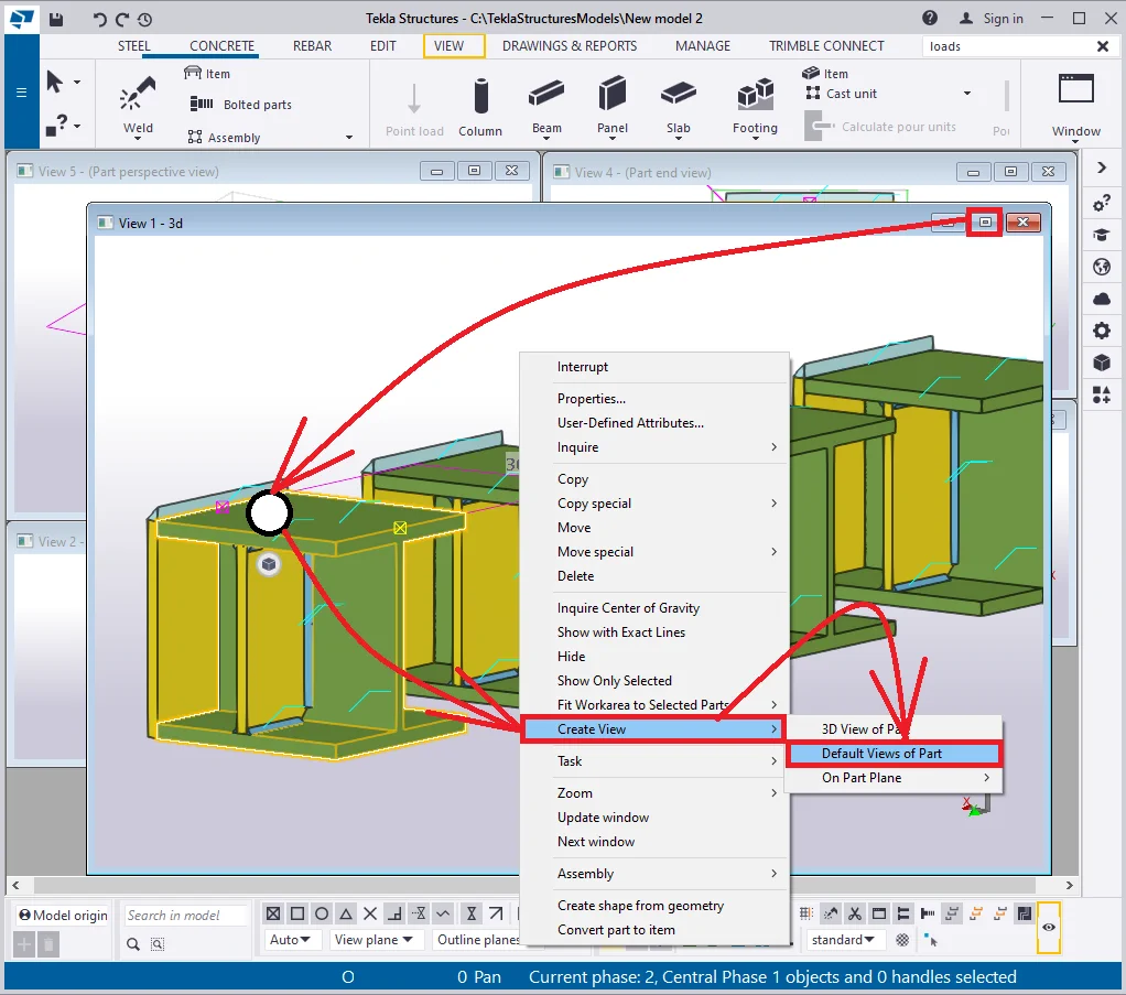
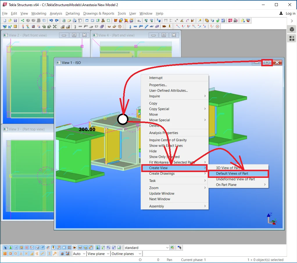
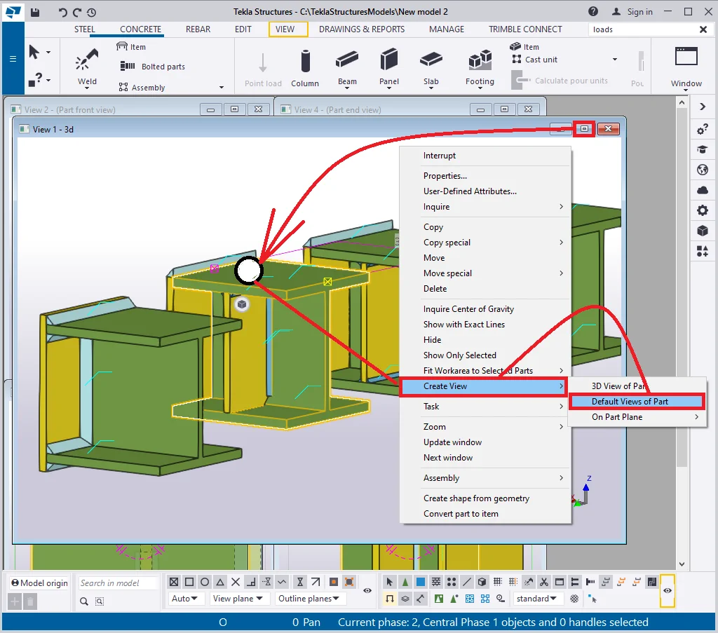
The “Create default views of Part” tool allows simultaneously creating various views of a selected part in the way the boundaries of the views are scaled down to the part’s dimensions, thus displaying only the required part of the structure.
Select a beam and enable the “Create default views of part”
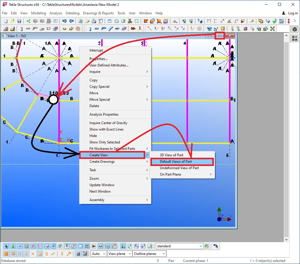
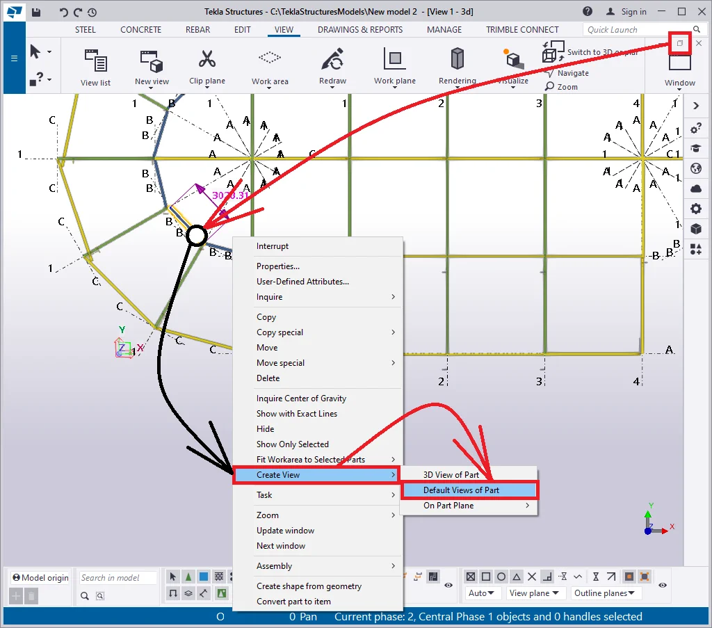
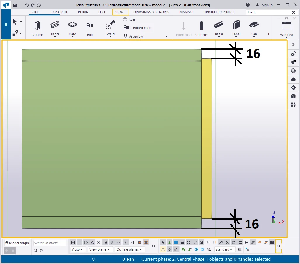
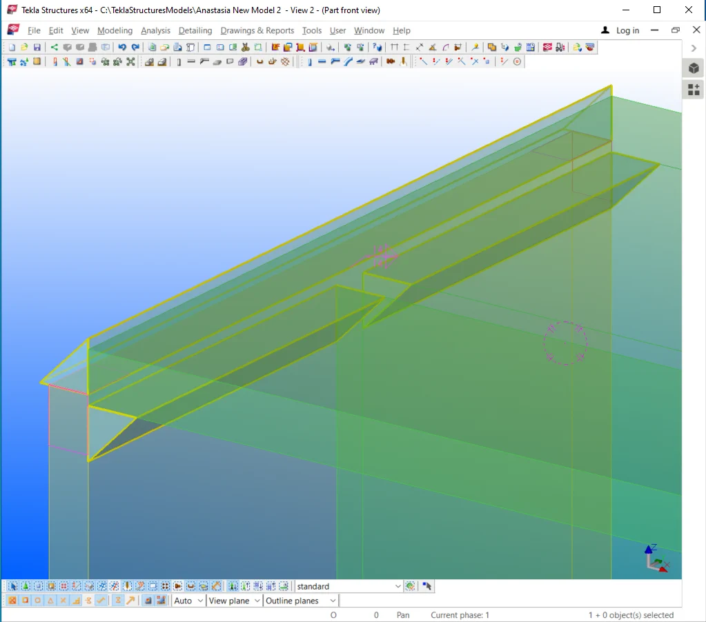
Thus we have got three different views and an additional 3D view.
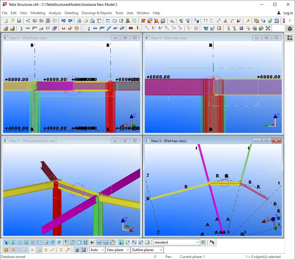
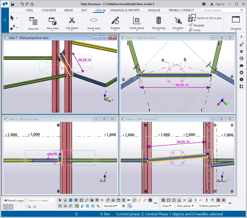
Note that the newly created views display all the elements of the structure which are adjacent to the selected part. Thus using this tool makes it convenient to examine structural elements in all the planes, as well as adjust connections, but not components.
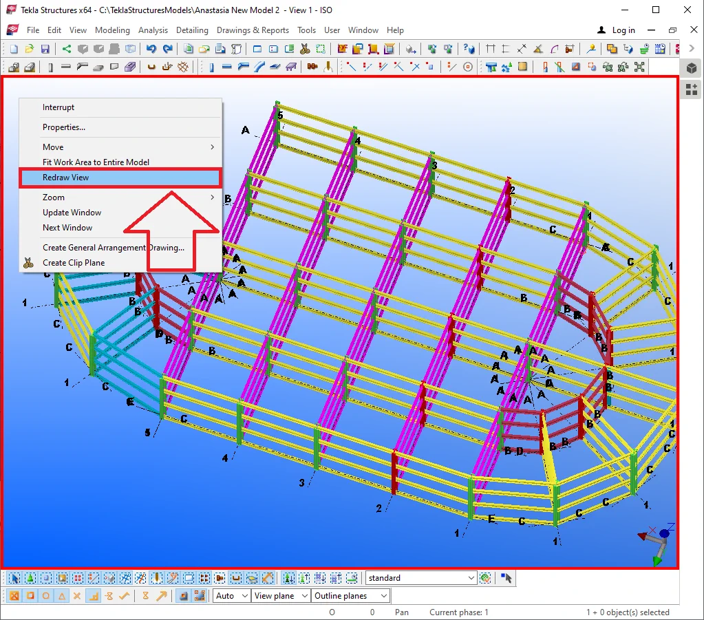
It is often caused, there is a need to partially hide several structural elements avoiding changing the work area view borders. By using the “Hide” tool it is possible to withdraw any parts located at any place. To enable the tool to proceed on selecting a required element and in the right-click menu activate the respective tab.
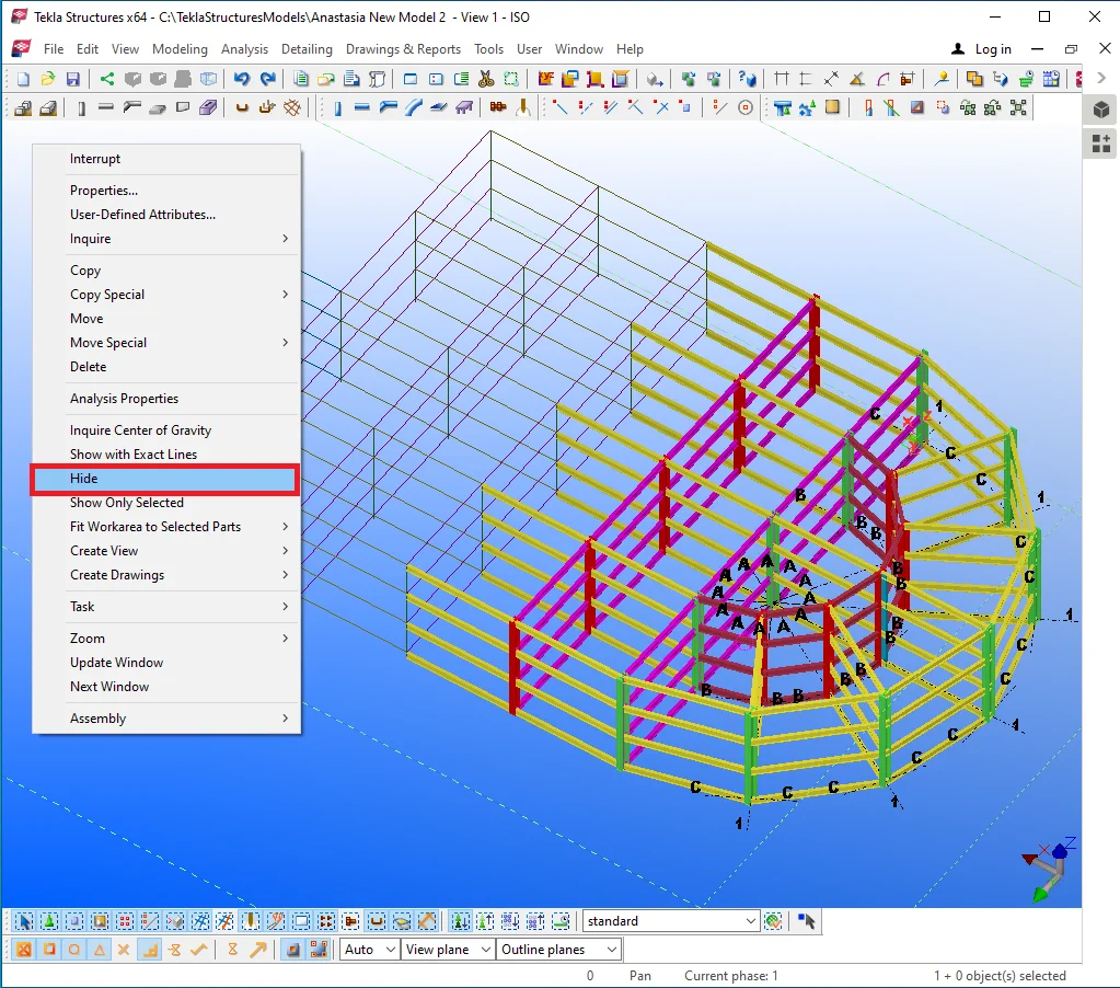

Hidden elements, such as beams and columns, are displayed as simple wires, or lines, with no regard to the profile types. Plates are displayed as lines intersecting at the vertexes of the polygon shape.
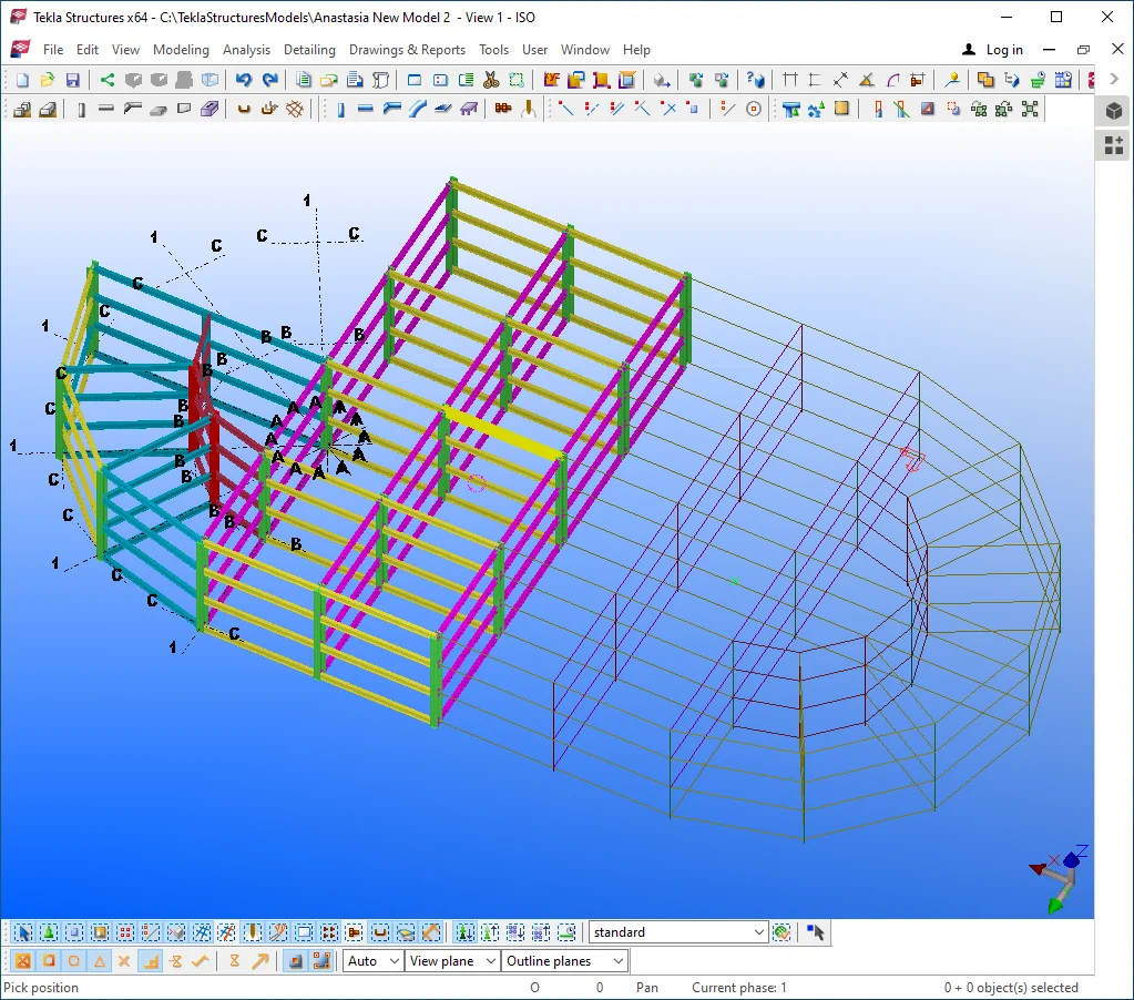
To restore the view, select the respective tab in the right-click menu
Try out selecting and hiding other structural elements, as well as restoring
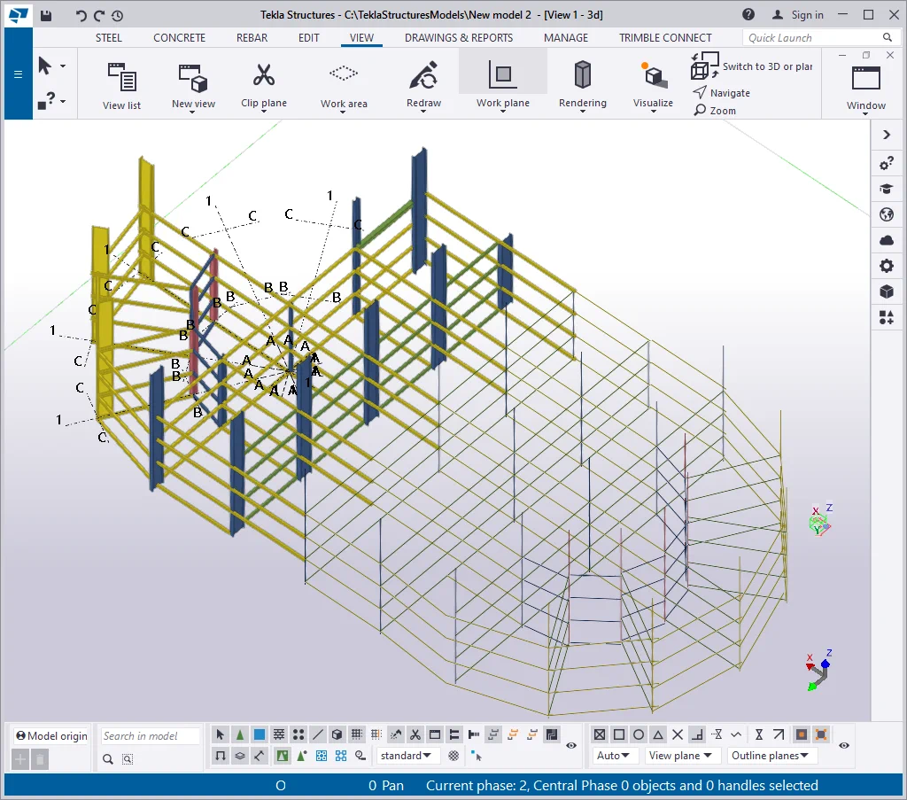
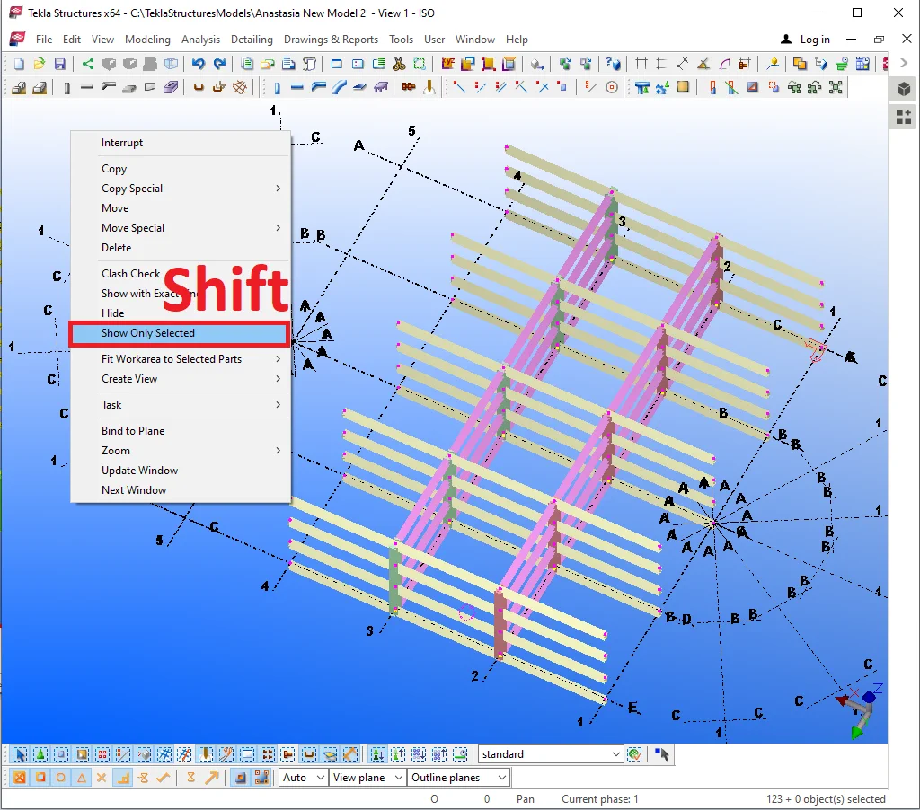
Till now hiding any element was followed by substituting it with a line. In case it is required to completely hide a part, then prior to selecting a part, press and hold on to the “Shift” key and proceed on enabling the “Hide” tool.

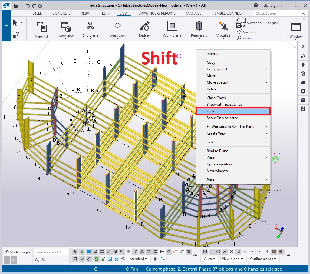
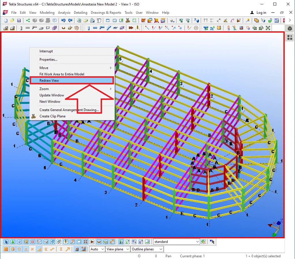
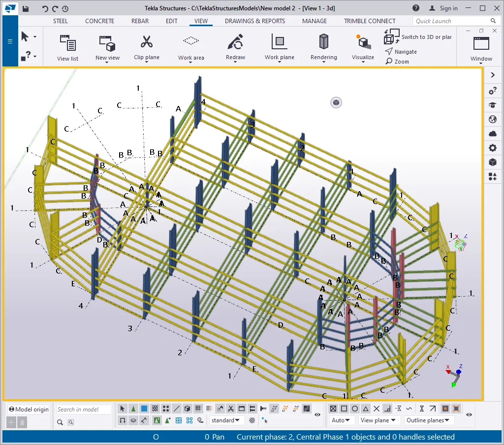
Thus the parts are completely withdrawn from the view. It is important to consider that hidden parts are not deleted. Redrawing the view automatically brings them back.


Restore the view.

The “Hide” tool is of frequent use. Try out yourself applying
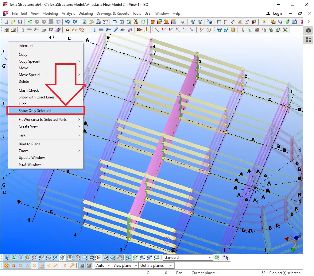
This tool works adversely to the previous one as it displays only the selected parts. Let's try it out: select several structural elements, and in the right-click menu enable the respective tab.
Non-selected parts now are gone transparent and are not restored when
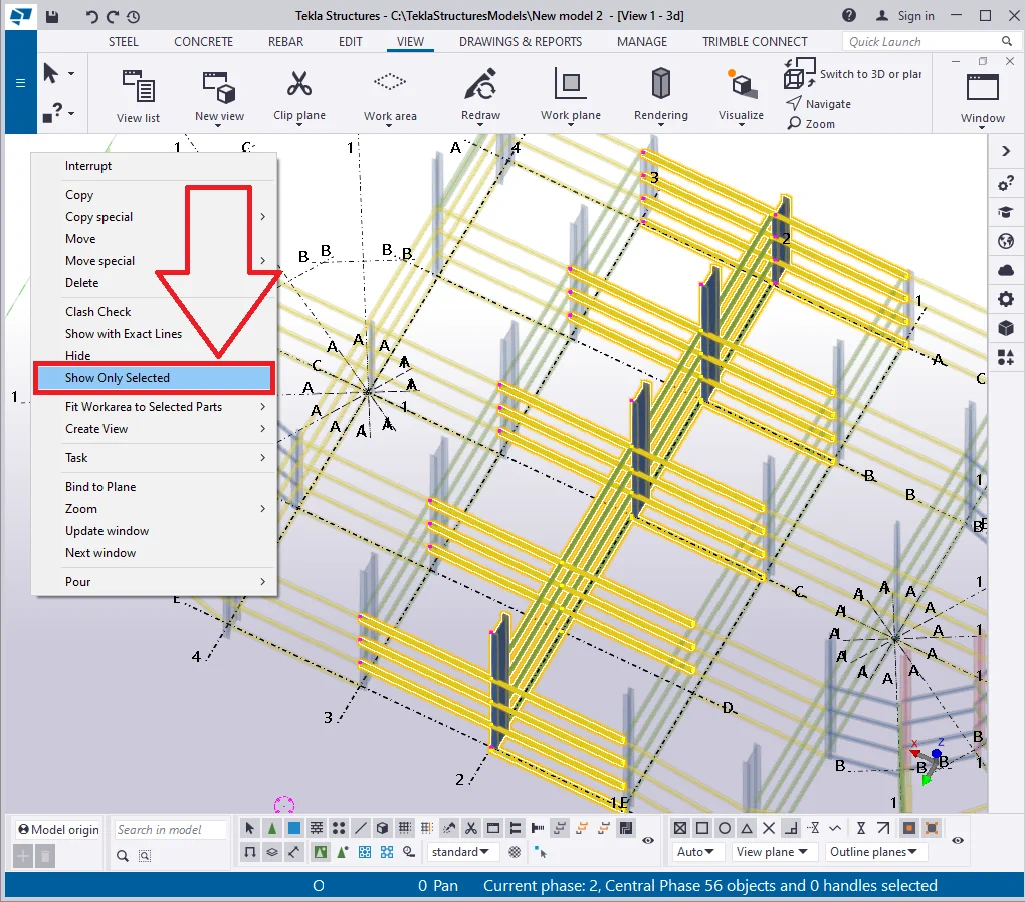
Redraw the view by enabling the respective tab of the right-click menu.

There is an additional effect of the "Show only selected" tool
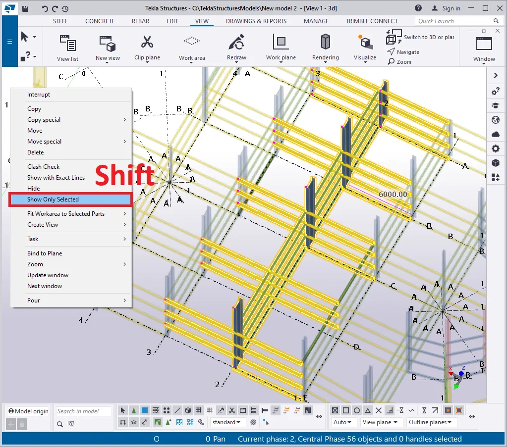
Thus all the elements got hidden except for the selected ones.
This tool for the short term shows the real profiles with a physical rounding
Select an arbitrary column and hide all the adjacent elements.

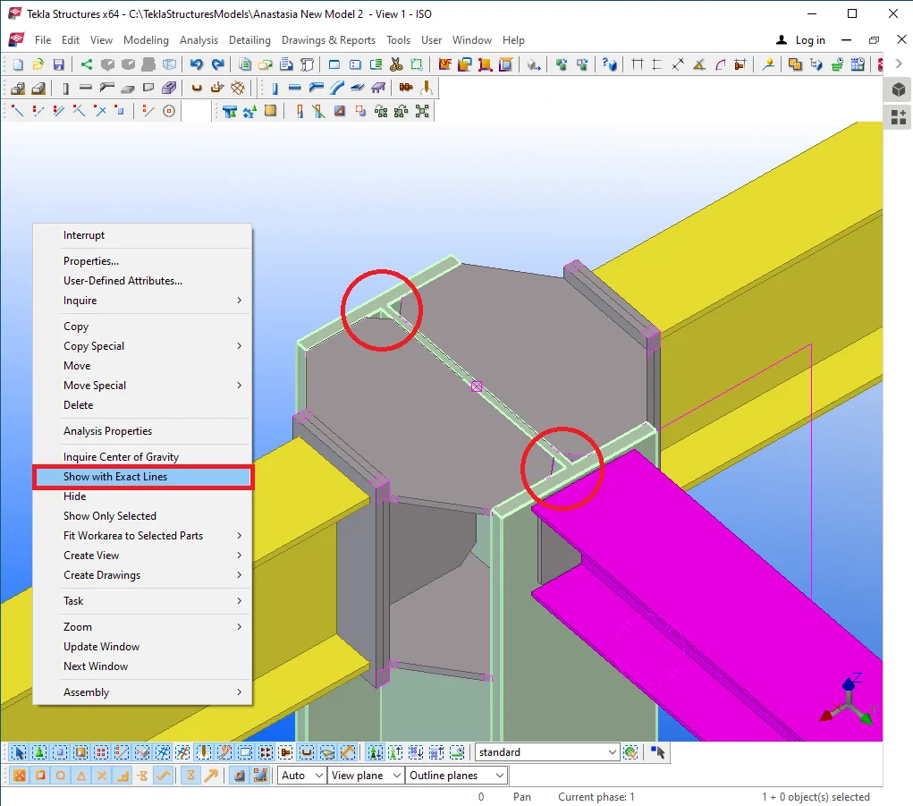
Select the column, and at the right-click menu enable the “Show with exact lines” tab by simultaneously holding on the Shift key pressed. Thus all the rounding radiuses will get displayed at an extended precision.

Redraw the view and apply the tool to all the adjacent to the column elements.
To deactivate the tool, go to the right-click menu and select the same
In practice, it is more convenient to work without reflecting the rounding