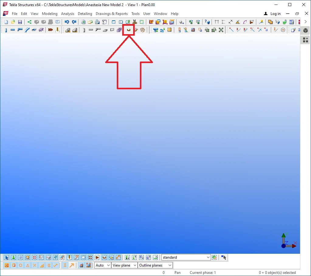
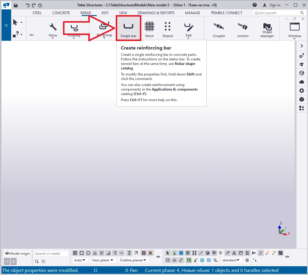
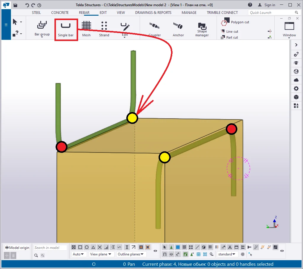
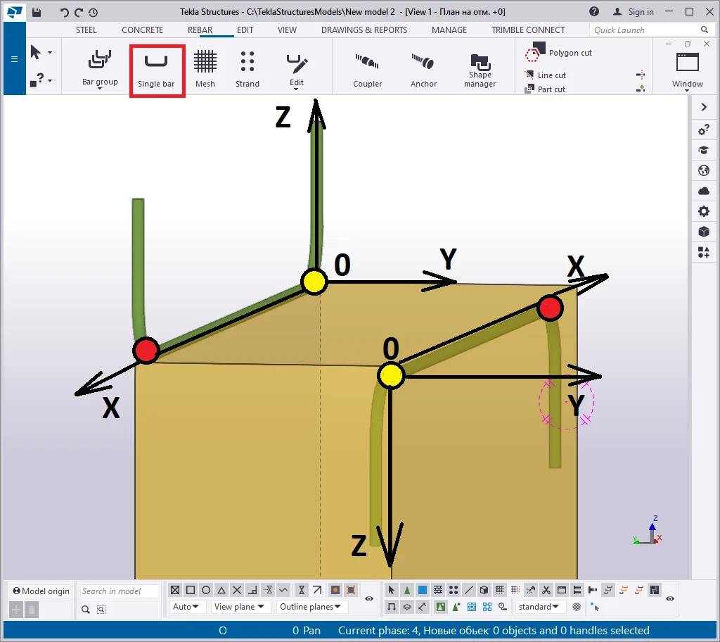
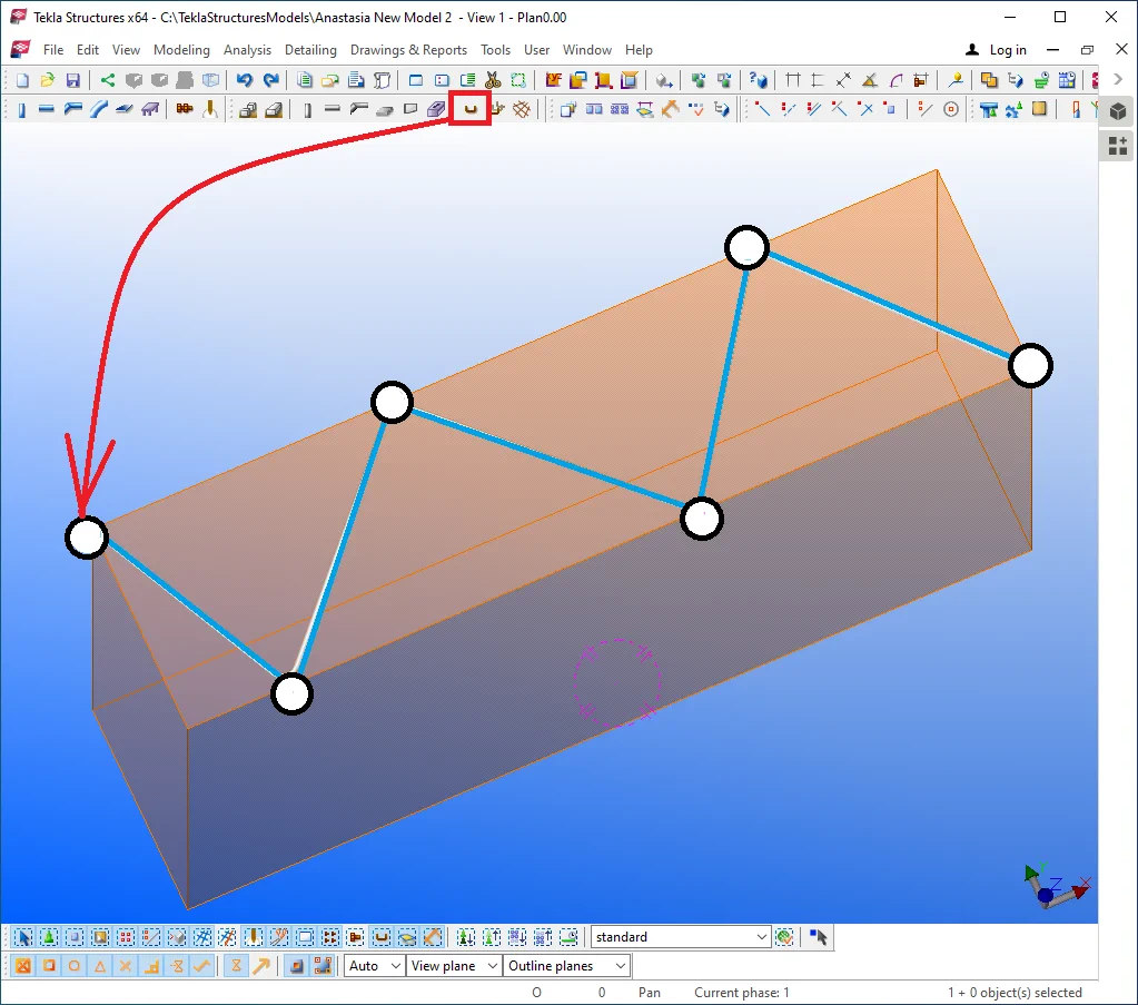
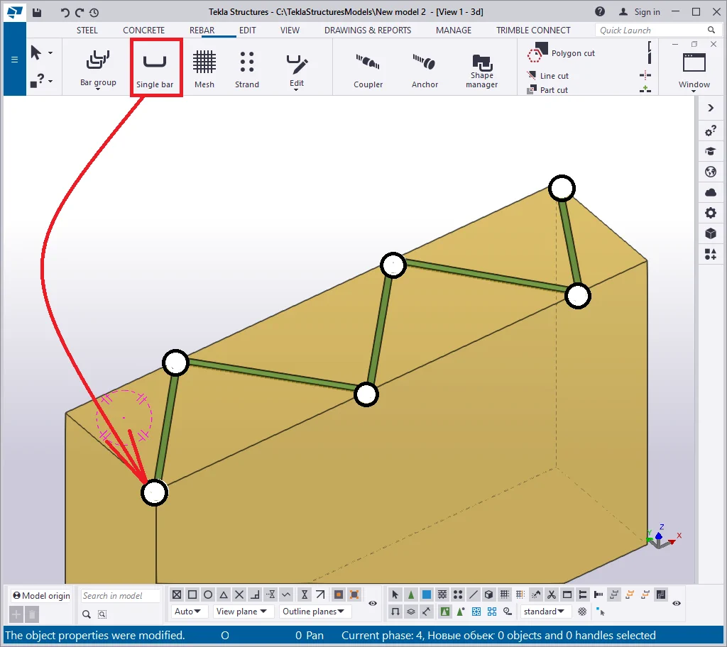
The "Single bar" tool allows creating a reinforcing bar of an arbitrary shape. It is a basic and the simplest tool. Find it at the main menu ribbon.
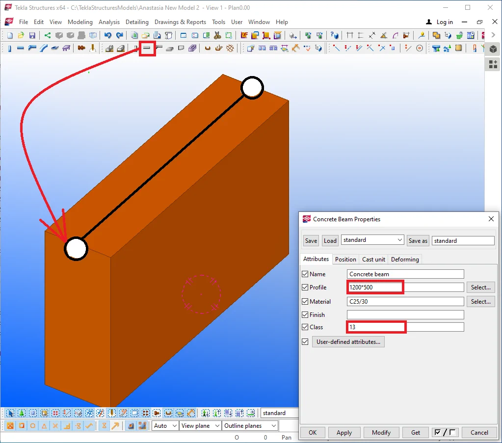
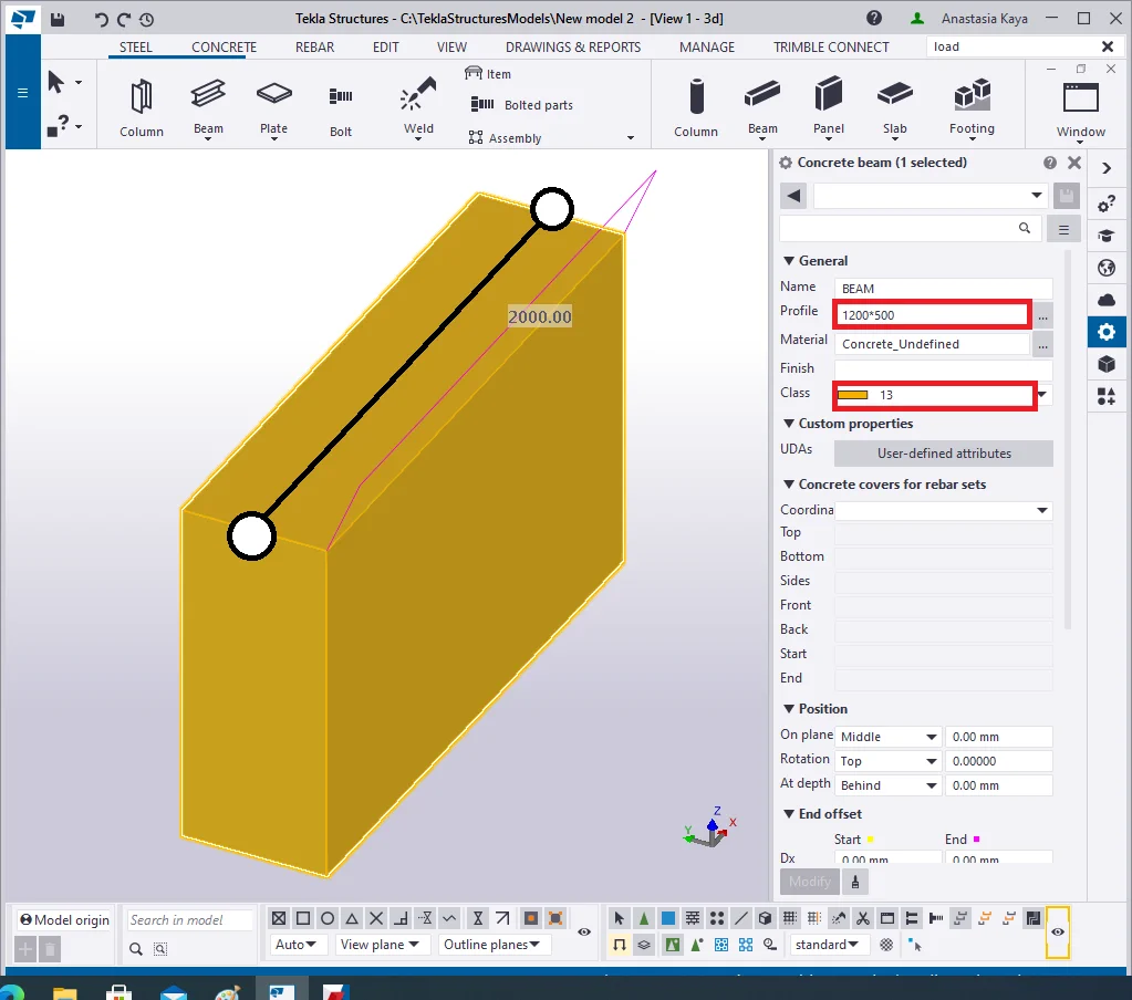
To examine the tool in action, create an arbitrary concrete object with a single reinforcing bar, and of 2000mm length, 1200*500 profile value and 13 th class.
The algorithms for using the "Single bar" tool is as follows:
Previously, when finalizing setting out object's coordinates, we were using both: the mouse wheel button and the "Space key". In the "Single bar" tool's case, pressing the "Space" key is not valid anymore.


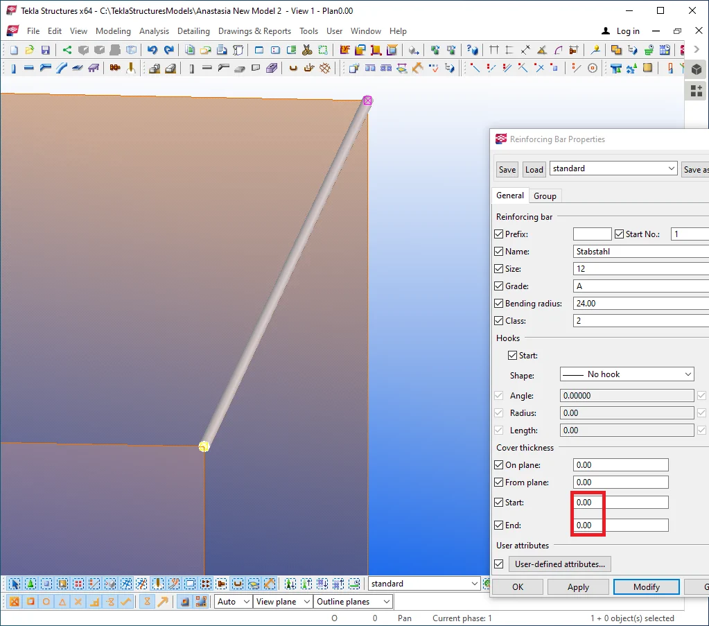
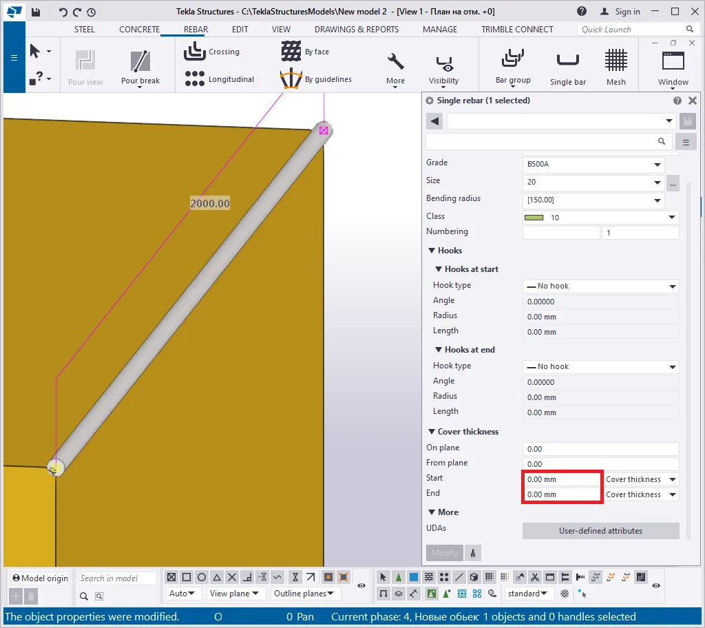
To get the result similar to the below, go to the "Reinforcing bar Properties" menu and set out "Cover thickness" parameters at 0.
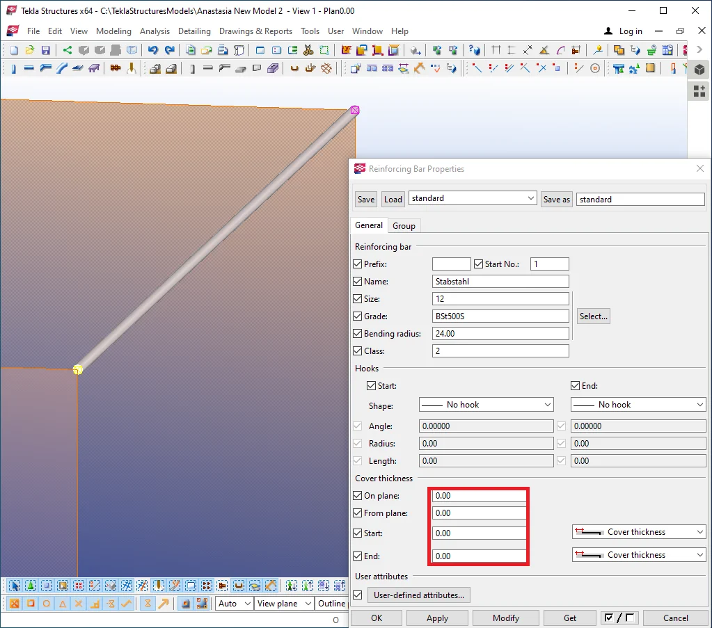
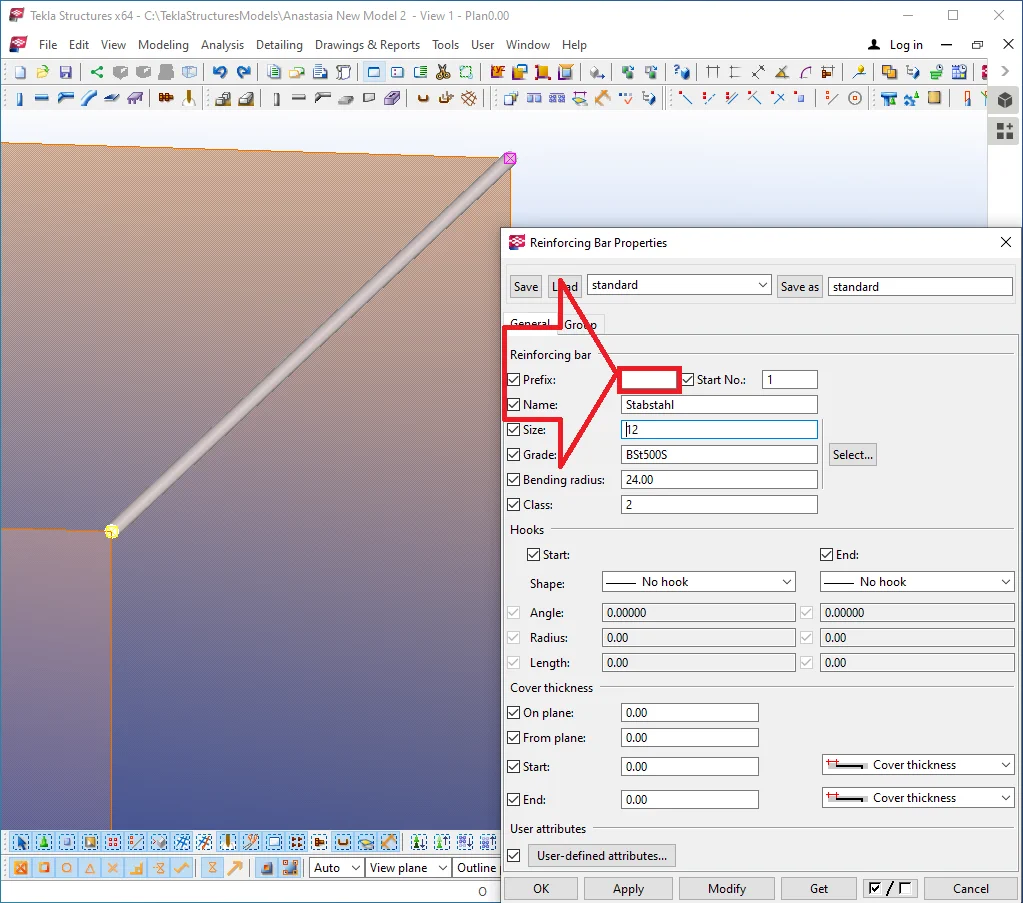
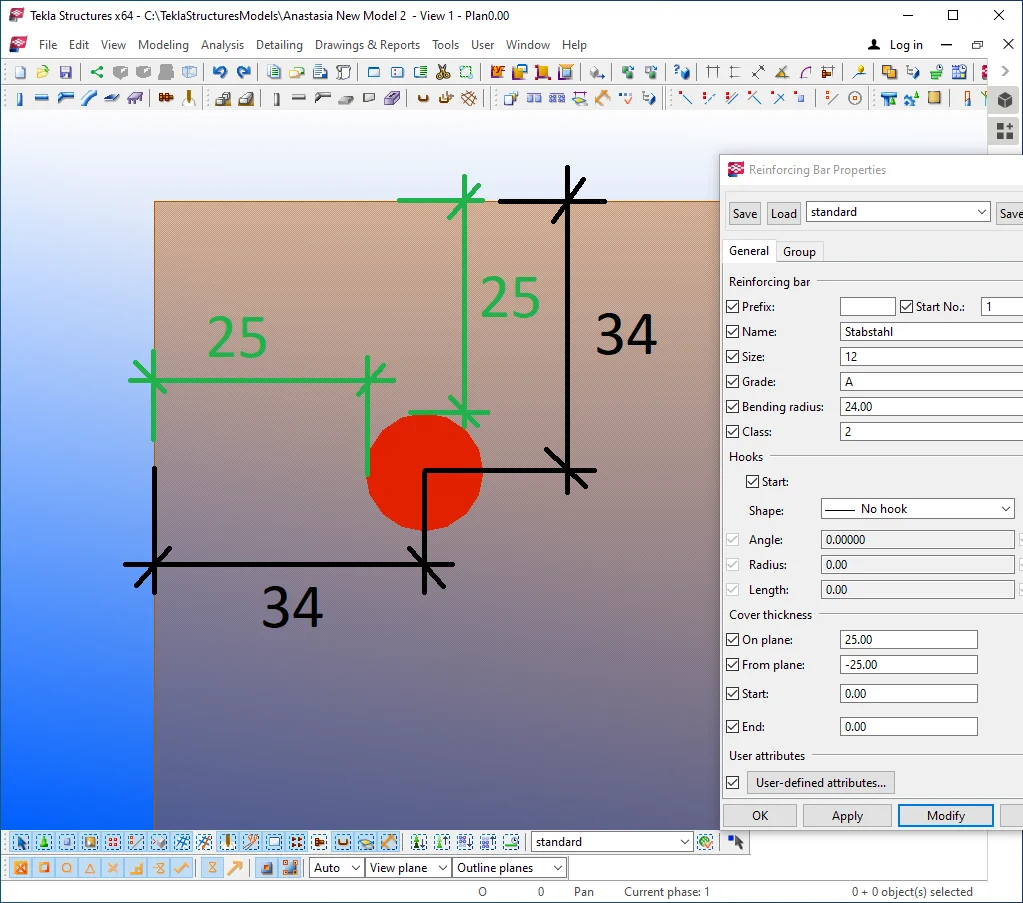
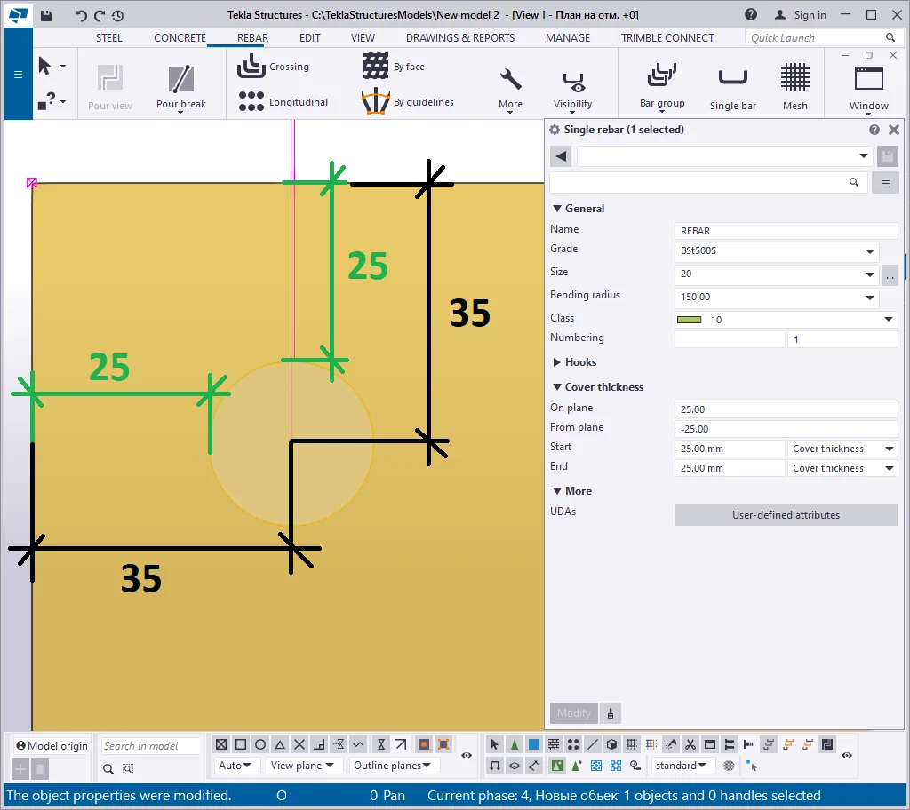
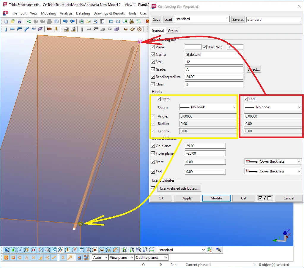
Go to the "Reinforcing bar Properties" menu.
The "Prefix" field" allows creating numbering of the reinforcing bars similar to the steel objects.
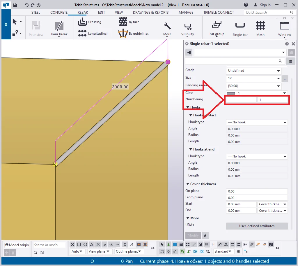
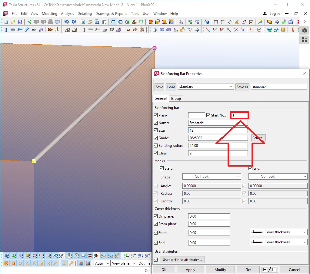
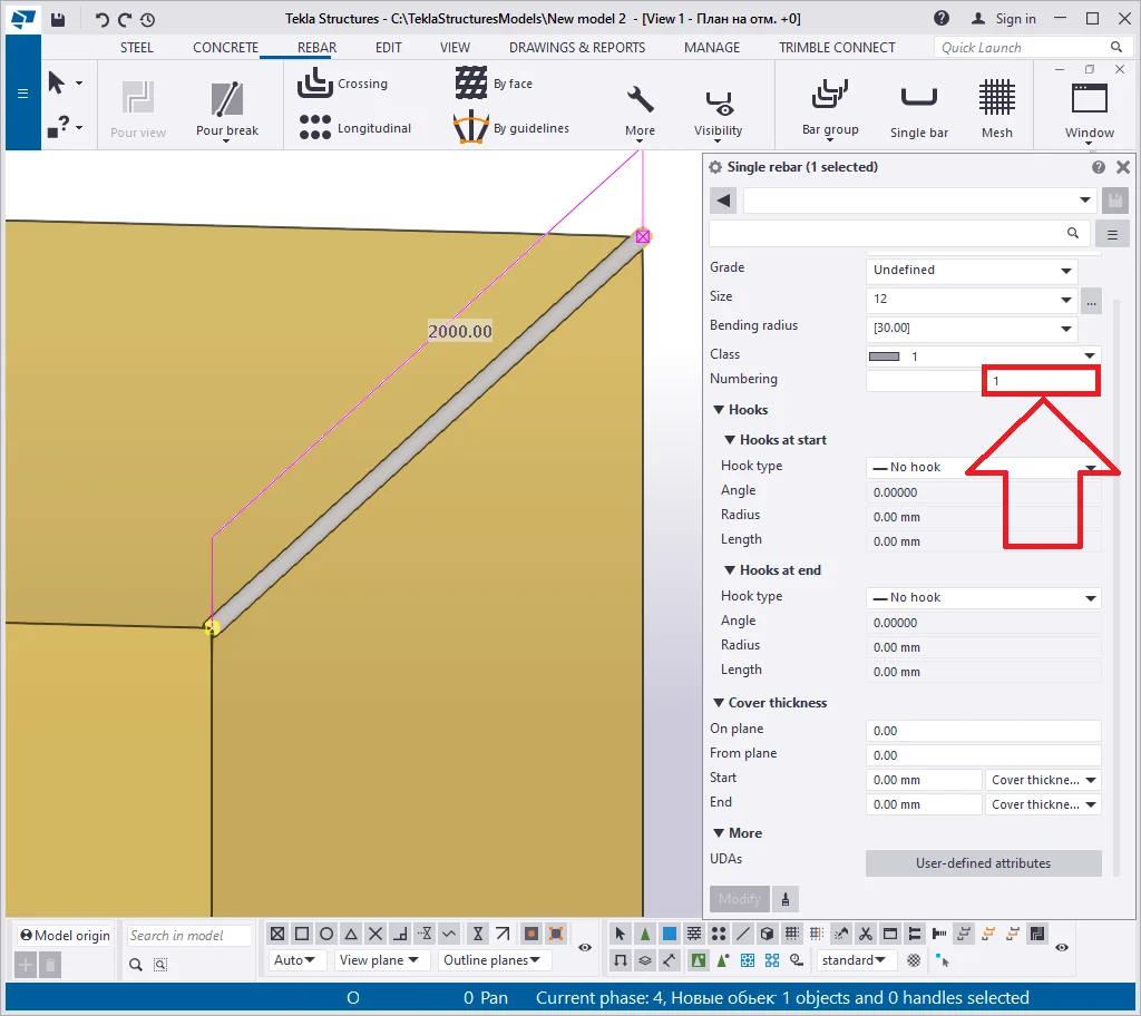
The "Start number" field works similarly to the respective of the steel objects and allows indicating the reinforcing bars numbering starting value.
This field does not allow you to manually indicate the starting number in the specification as the numbering is done automatically. By default, this field is set out at 1, which means reinforcing bars are numbered as 1,2,3,4,5, etc.
If you indicate the "Start number" as 300, then reinforcing
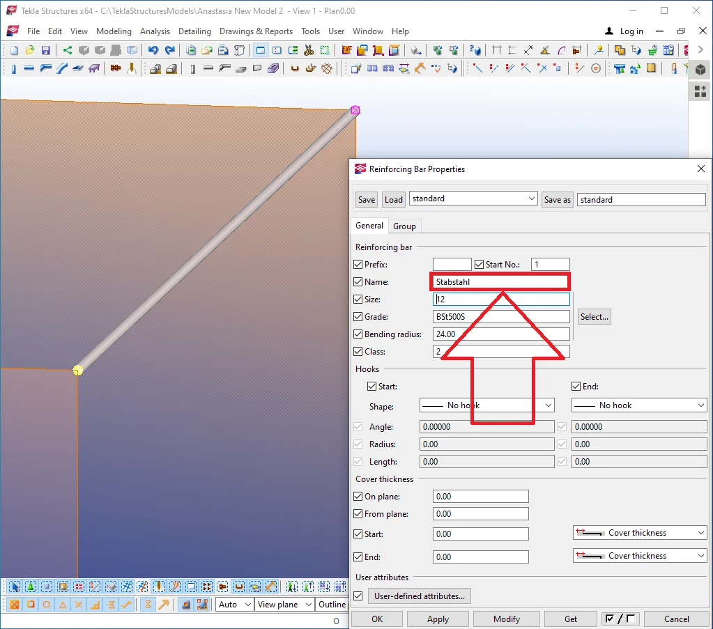
The "Name" field, analogously to the steel objects case, is used to indicate additional information about the reinforcing bar. This is a textual field containing information that is essential for statements and reports. We will investigate in detail the "Prefix" topic when getting to the "Drawings" chapter.

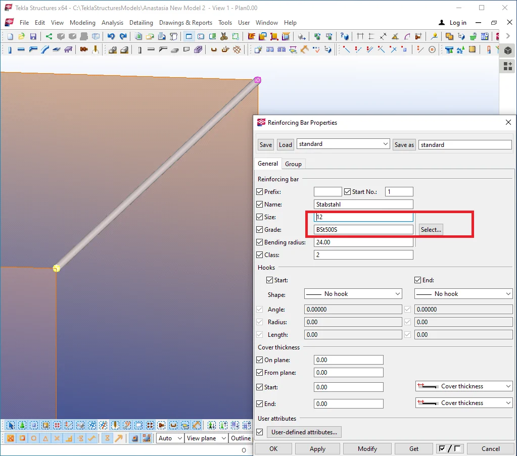
The “Grade”/”Size” fields work concomitantly: upon indicating the "Grade" value, it is possible to specify the diameter of the reinforcing bar. The "Grade" value defines the range of the reinforcing bars applicable to it. According to a country's regulations, there are admissible diameters of the reinforcing bars correlated to their range.
Let's get to the "Select rebar" catalog available with your
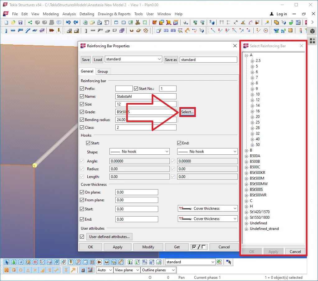
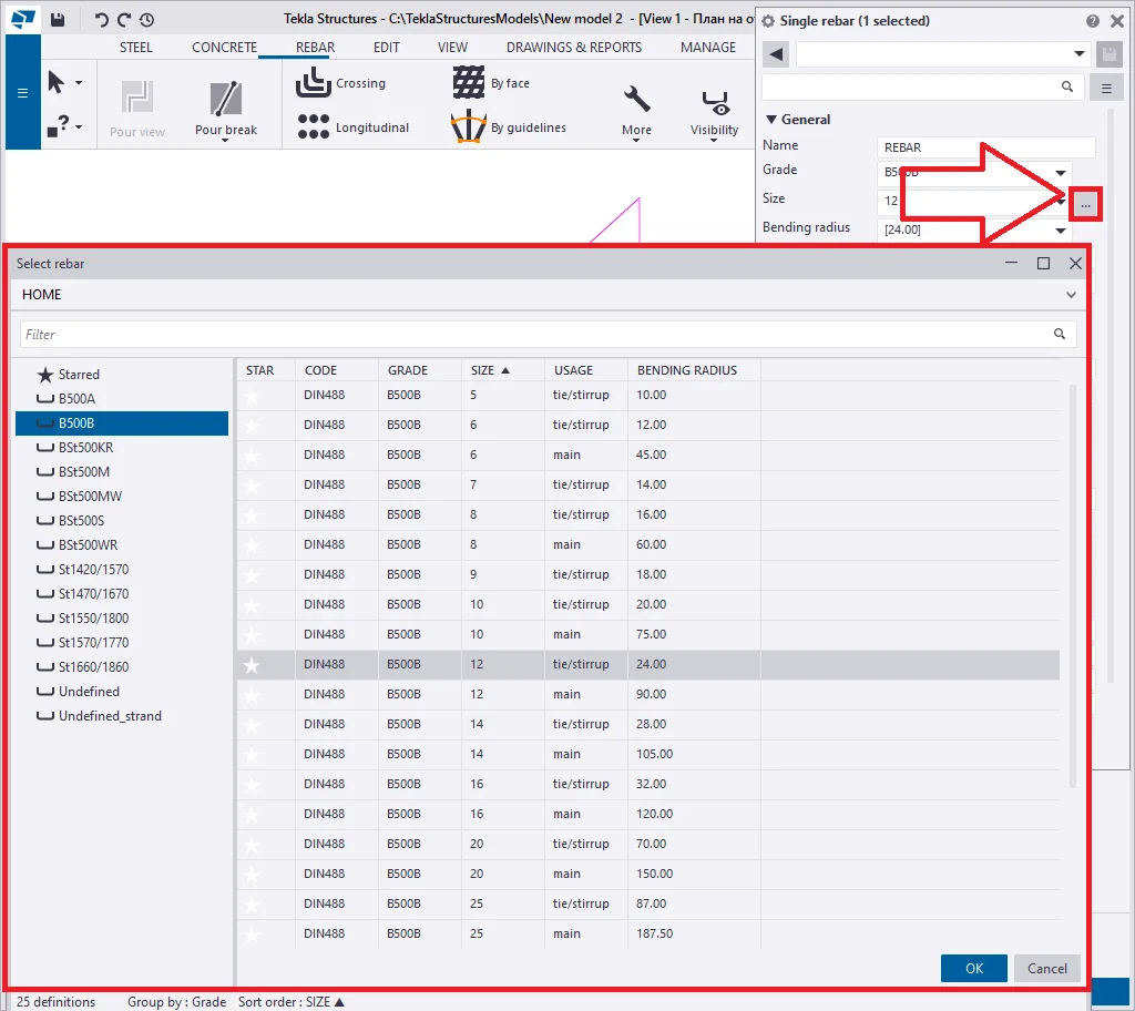
Depending on the Tekla Structures version, the "Select rebar" catalog looks different, though the function of the options available is the same. Select the "Grade" required, further, proceed to select the reinforcing bar diameter, and its "Usage" type: main, tie, stirrup. The available "Grade" list depends on your country's regulations and standards.
Indicate any "Grade" and "Size" options in the "Select
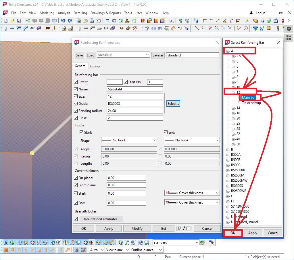
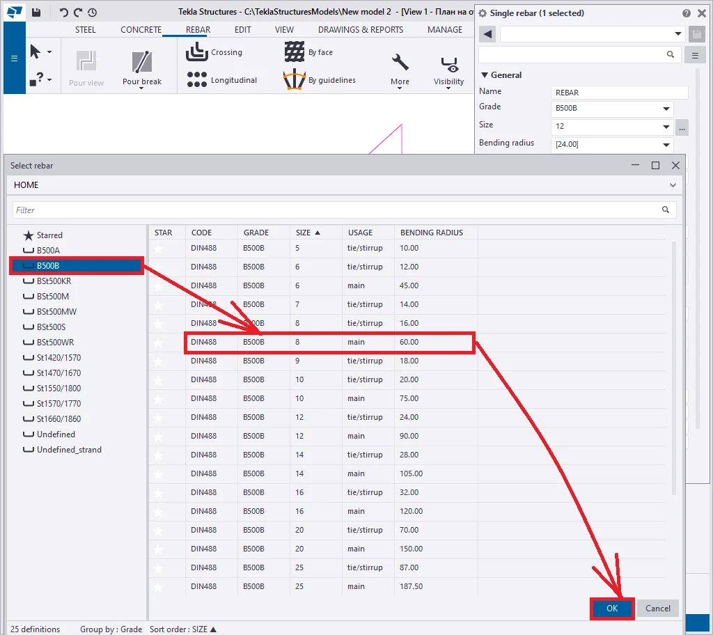
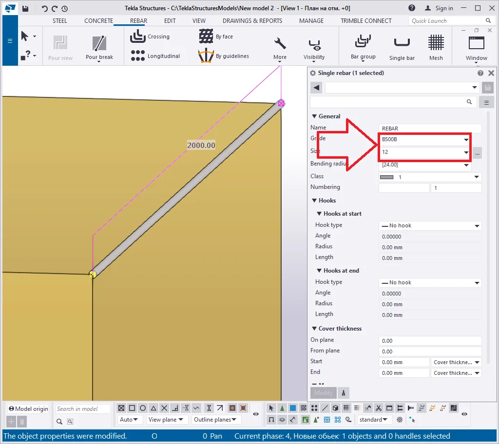
Note that upon executing the above, several fields have concomitantly
In case you know the grade value and the required diameter size, you can introduce them manually into the respective fields. Thus experienced users can swiftly configure the reinforcing bar without recurring to the "Select rebar" catalog.


The "Class" field stands for configuring the color-coding of the reinforcing bars. It does not influence the drawings. Configuring the colors in the drawings is done another way. This field facilitates rendering various types of reinforcing bars.
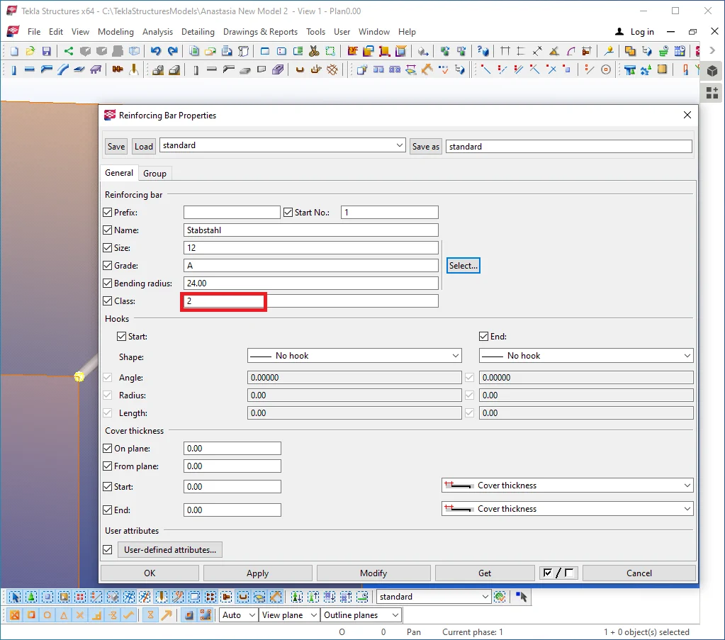
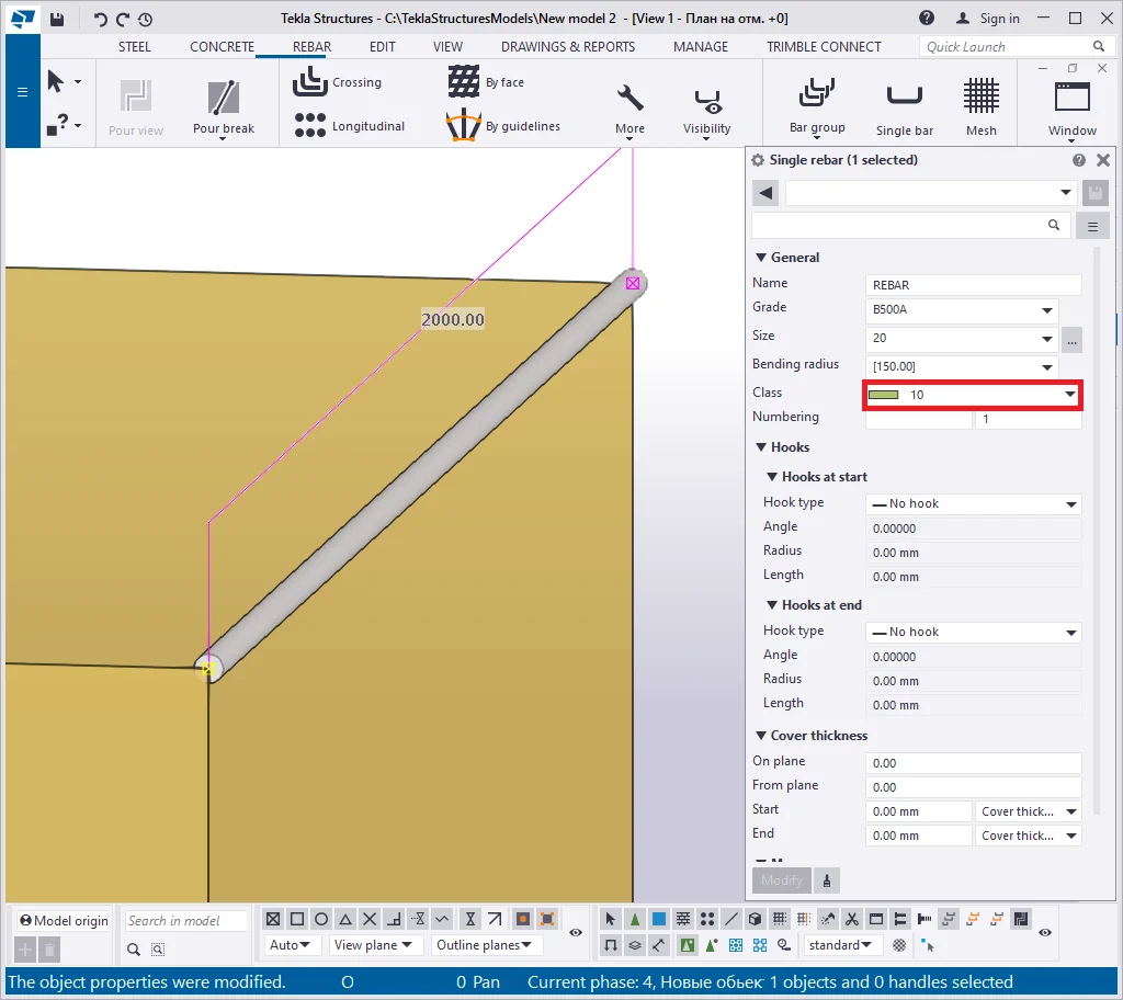
Toggle between all the "Class" field options. We do recommend setting out the "Class" value equal to the diameter of the reinforcing bar.
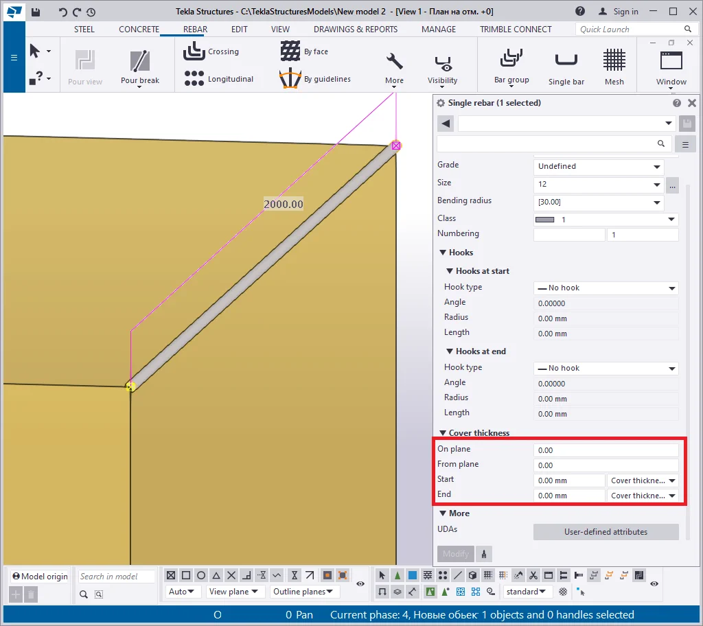
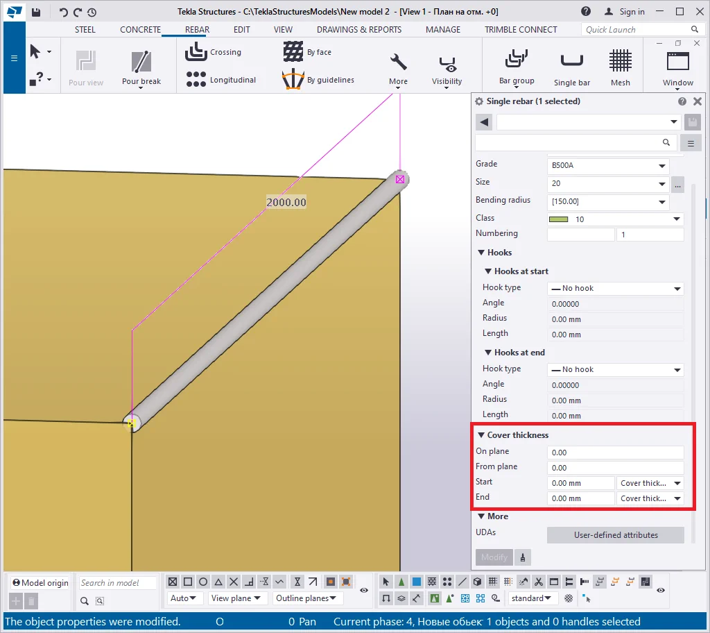
The “Cover thickness” section represents a variable set adjusting the unconfined concrete thickness in all directions. In other words, this section defines the space from the concrete edge.
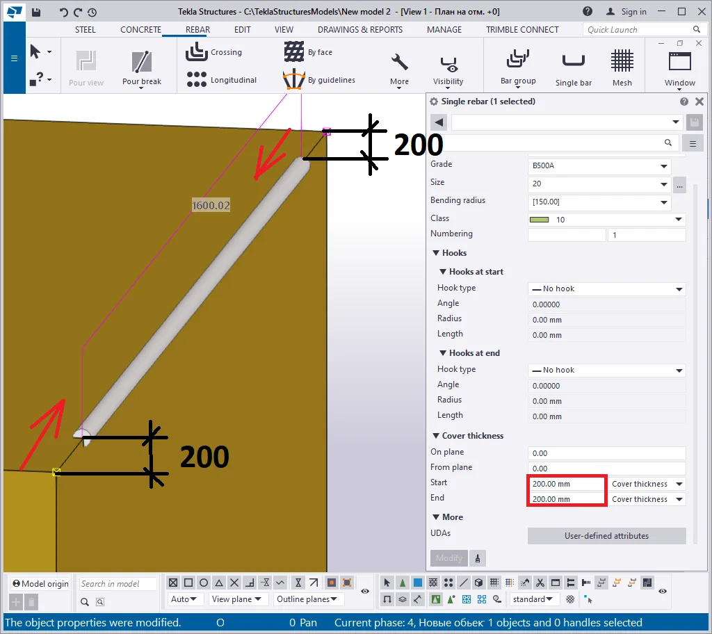
See below framed in red the parameters setting out the unconfined concrete
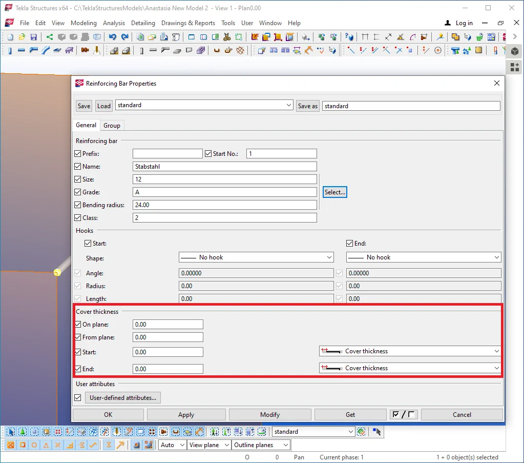
The unconfined concrete necessity.
Reinforcing bars shall be protected from humidity, on the reason that rust is greater in volume compared to the initial material of the reinforcing bar, thus causing intrinsic pressure in the reinforced concrete object. Thus all the reinforcing bars shall not be in contact with the environment. The unconfined concrete thickness is a regulatory parameter, fluctuant from one country's regulations to another. Prior to modeling the reinforced concrete structures, make a profound study of your country's regulations.
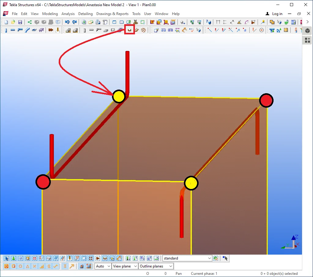
As we mentioned above, the reinforcing bar has its starting (marked with yellow) and end (marked with red) points. Let's offset the reinforcing bar into the concrete object body at 200 mm (the value of 200 mm is an arbitrary one as, in reality, it shall be around 20-50 mm).
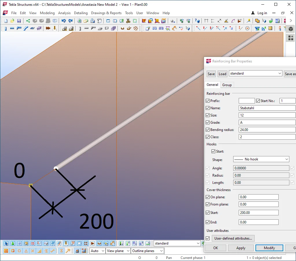
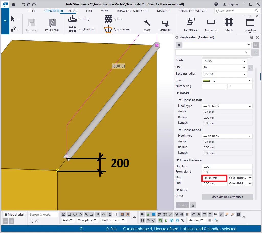
After pressing the "Modify" button, the reinforcing bar starting point is offset into the concrete body at the indicated distance. Let's indicate a negative offset value, for example, -200 mm.
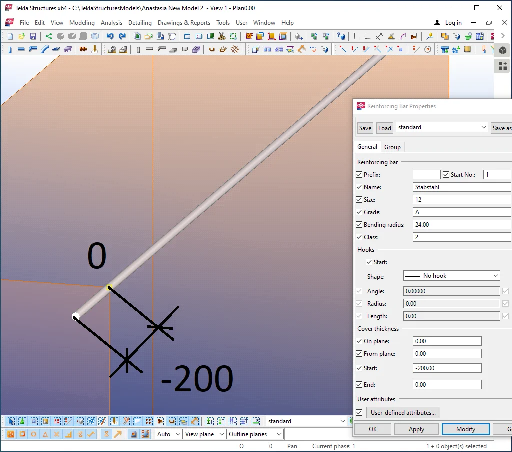
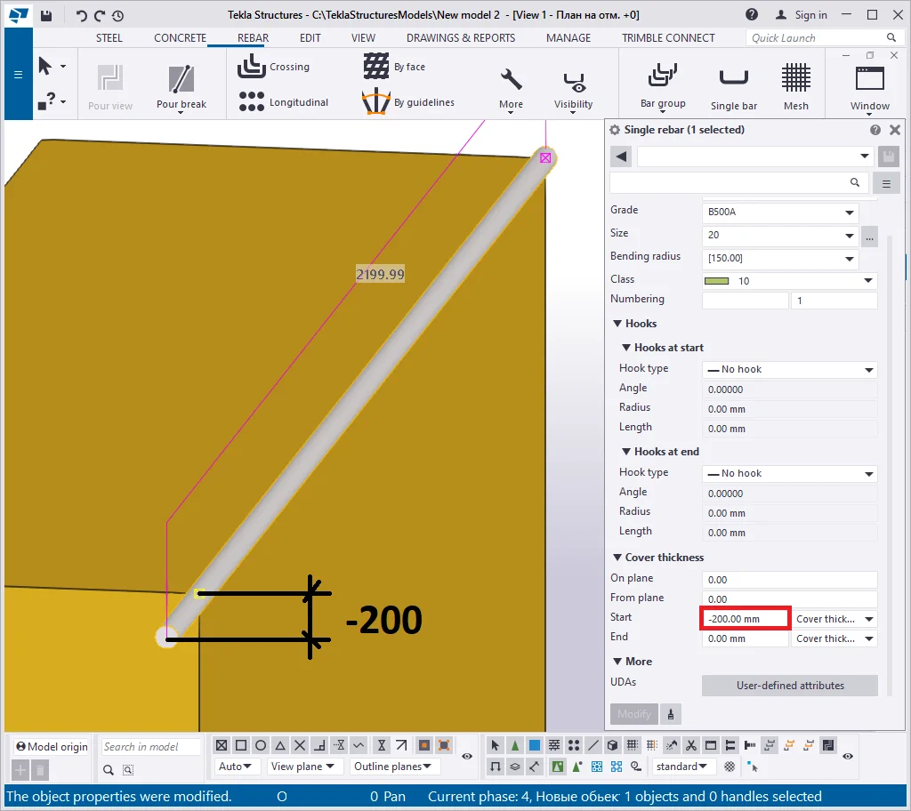
Now the starting point is offset in the opposite direction. Thus in Tekla
Let's indicate the starting and the endpoint offset value of +200.
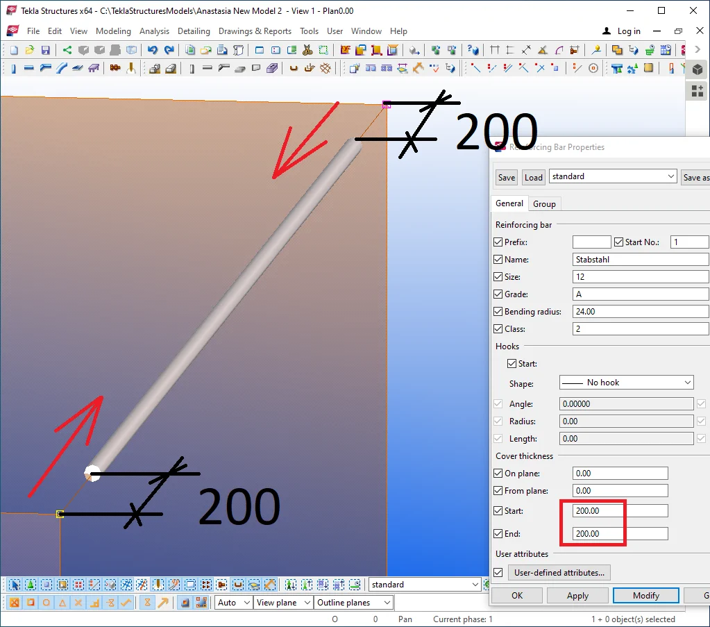
The positive direction of the unconfined concrete is pointed to the center
The "Cover thickness"/ "Leg length" parameter allows switching on/off the unconfined concrete by ignoring the starting and the endpoint offset values.
It is a very convenient parameter allowing to avoid null out the
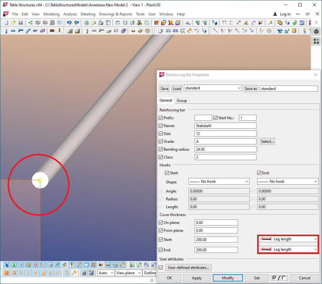
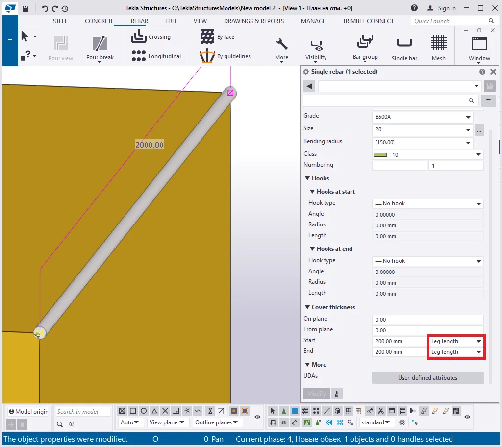
Null out the starting and the endpoint offset values.
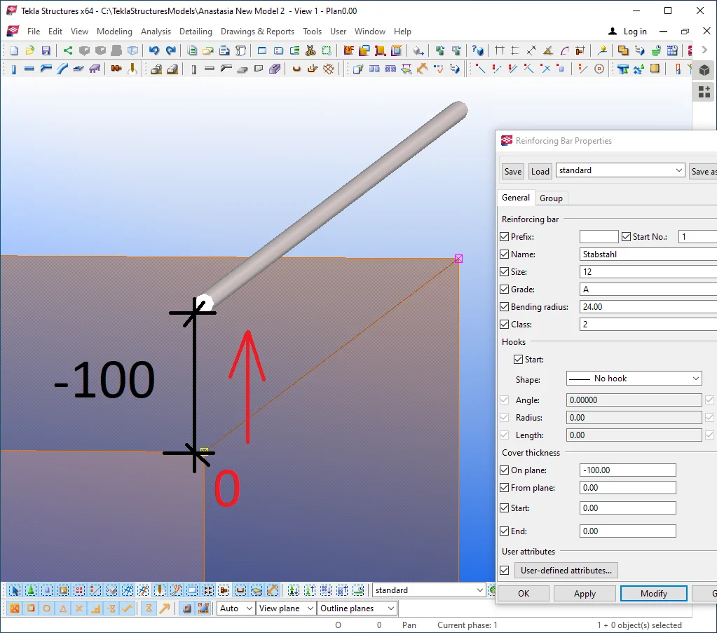
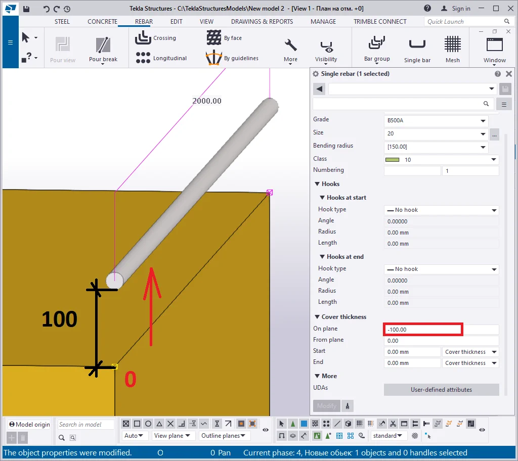
Indicate the offset “On plane” value as 100 mm.
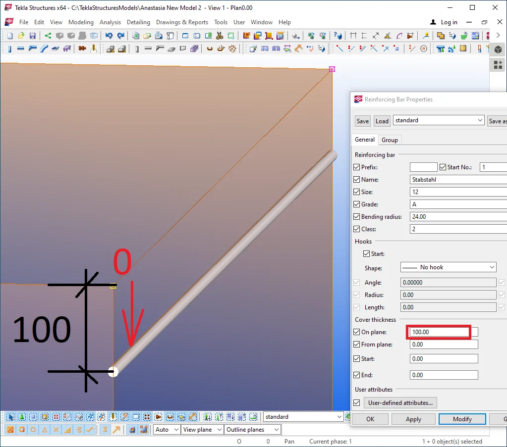
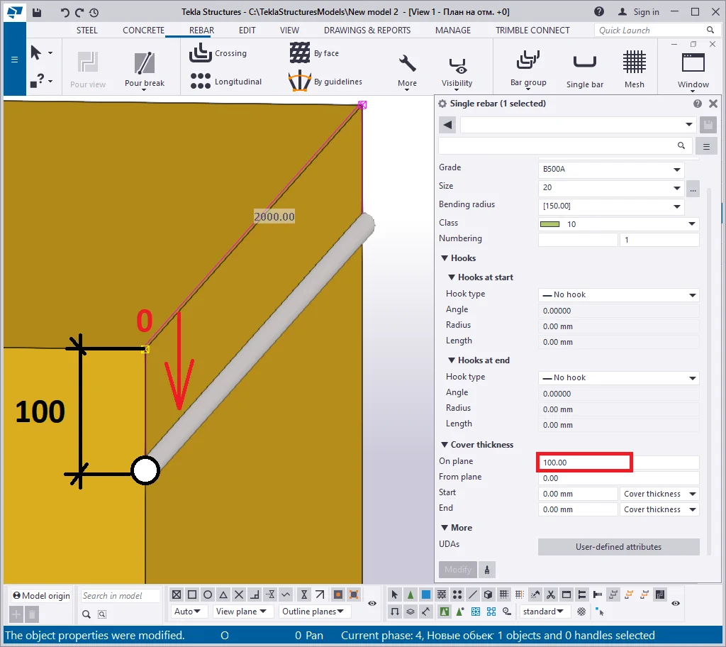
The reinforcing bar was offset vertically into the concrete object's body. The TS does not define the direction for the offset, thus the operation is performed about the local coordinates of the reinforcing bar. Thus users shall every time check on the offset result.
Indicate a negative value for the "On plane" offset to make
Restore the "On plane" offset value to 0. Configure the "From
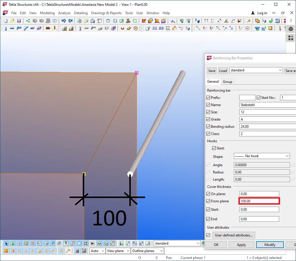
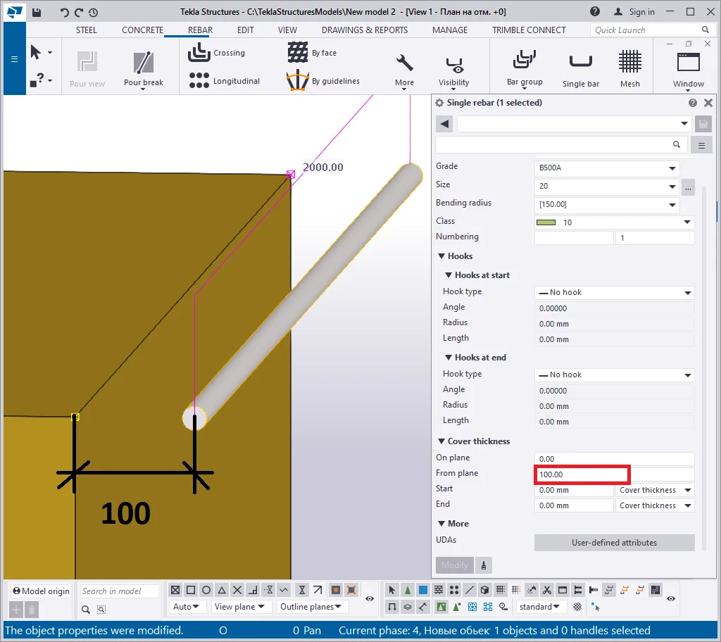
As you can see, the reinforcing bar offset is done by another axis. This
Indicate the unconfined concrete offset equal to 25 in all the directions in the way to get hidden into the concrete object body. Note that reinforcement is defined by a radius to be configured by the user. Thus the distance to the reinforcement edge is not equal to the reinforcement center. The "Cover thickness" section defines the distance to the reinforcement edge. The reinforcement center is defined by other coordinates, which are greater at the value of the reinforcement radius.
Never confuse the distance to the reinforcement center and the reinforcement
On updating the diameter of the reinforcing bar, the TS automatically offsets the reinforcement center to adjust the reinforcement bar allocation according to the "Cover thickness" section values.
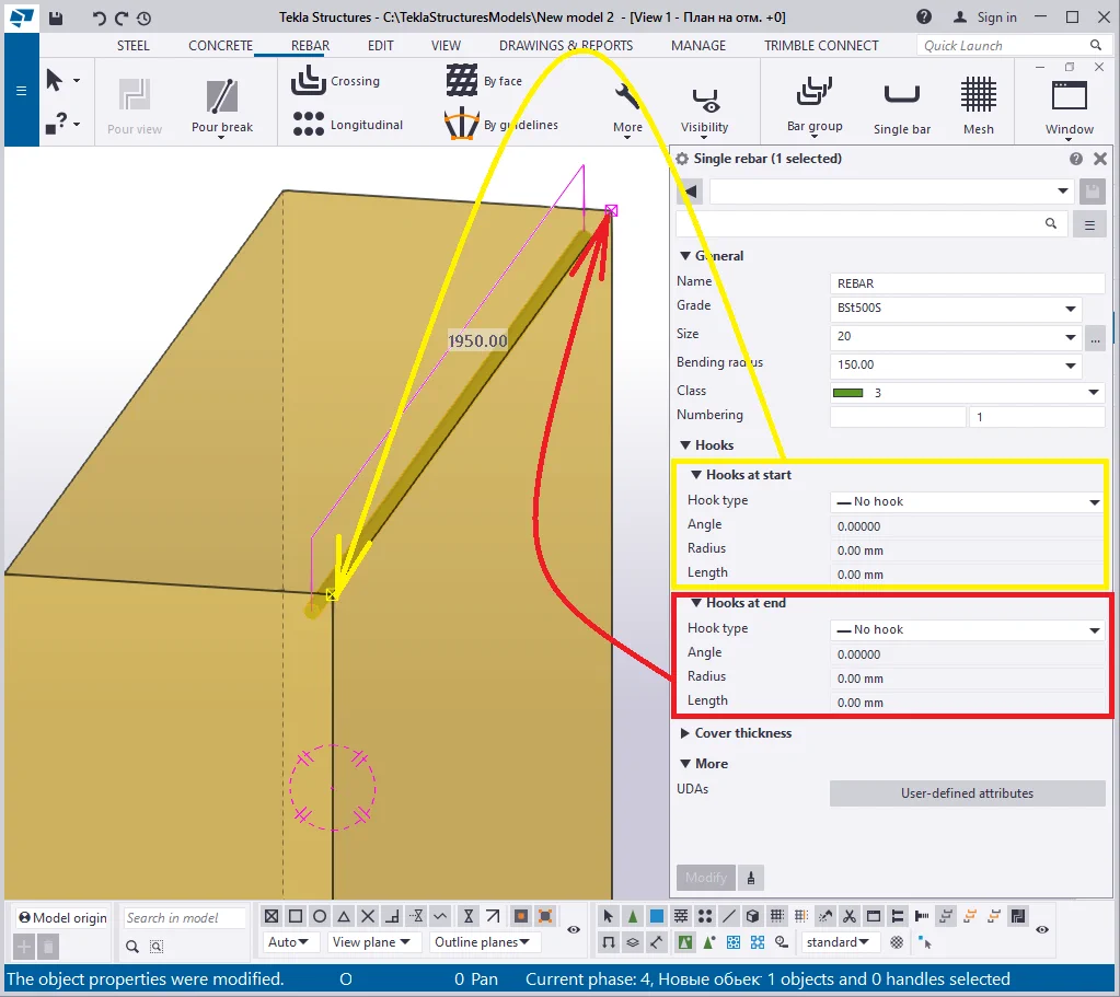
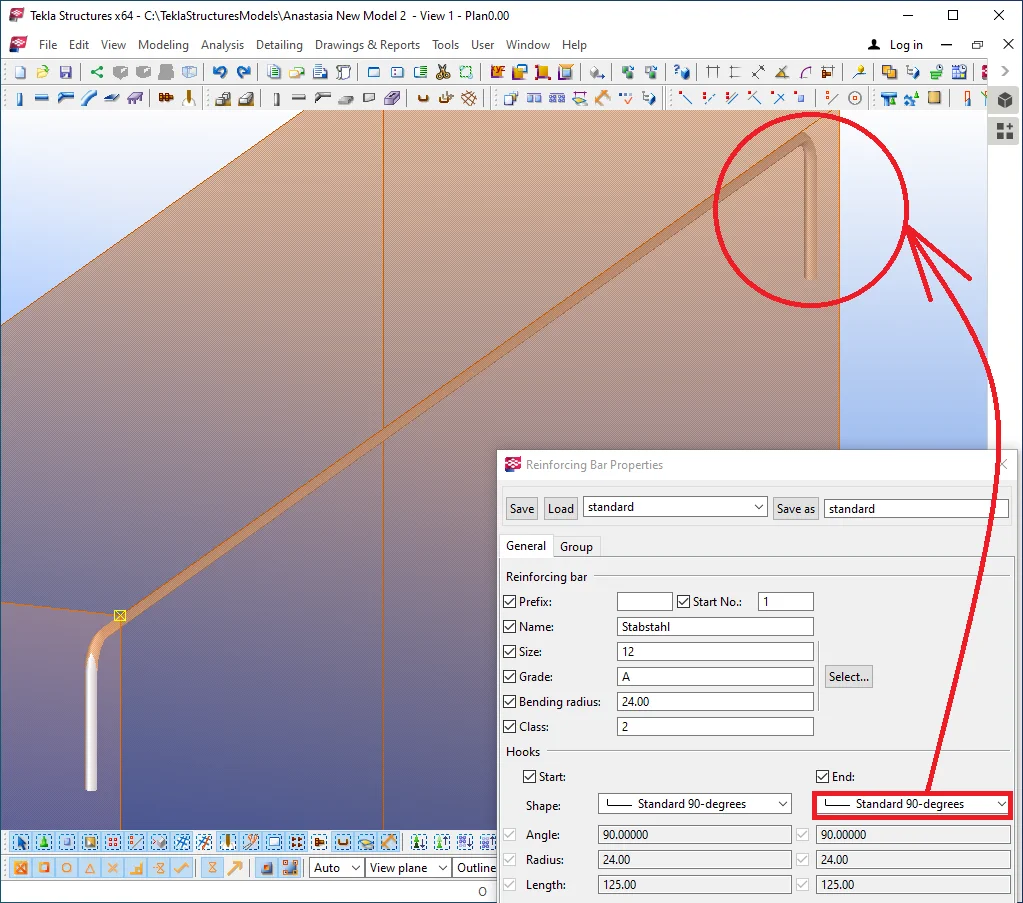
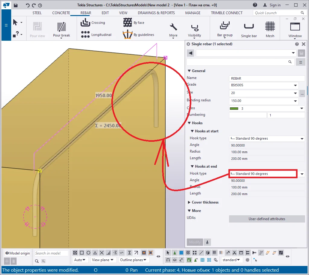
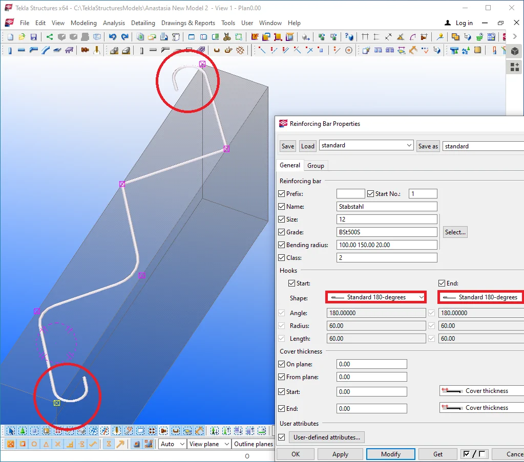
The “Hooks” section cambers the starting and endpoints of the reinforcing bar basing on the standard or user-defined options.
The reinforcing bar starting point is marked with yellow, but its endpoint
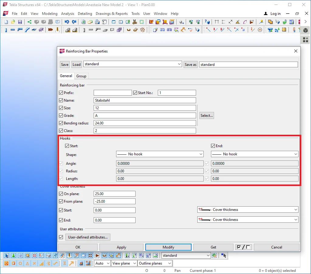
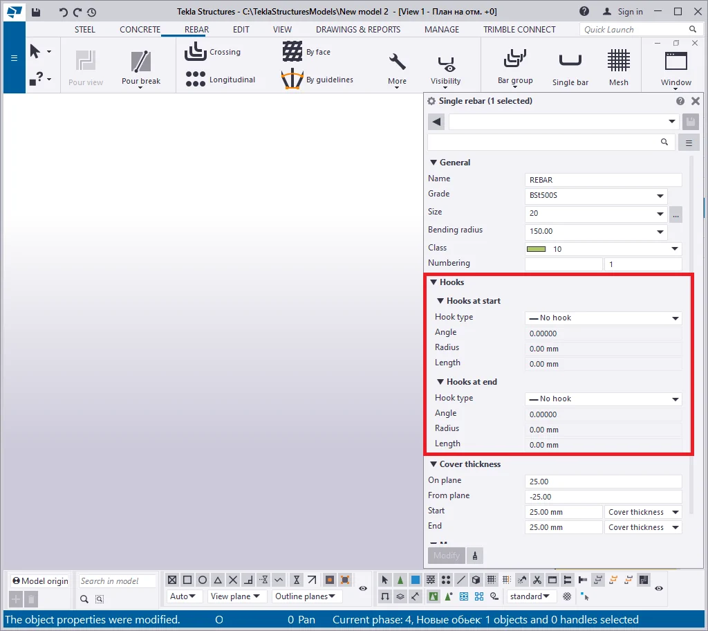
Let’s clarify which parameters of the "Hooks" section
Configure the hook type at the start as "Standard 90-degrees".
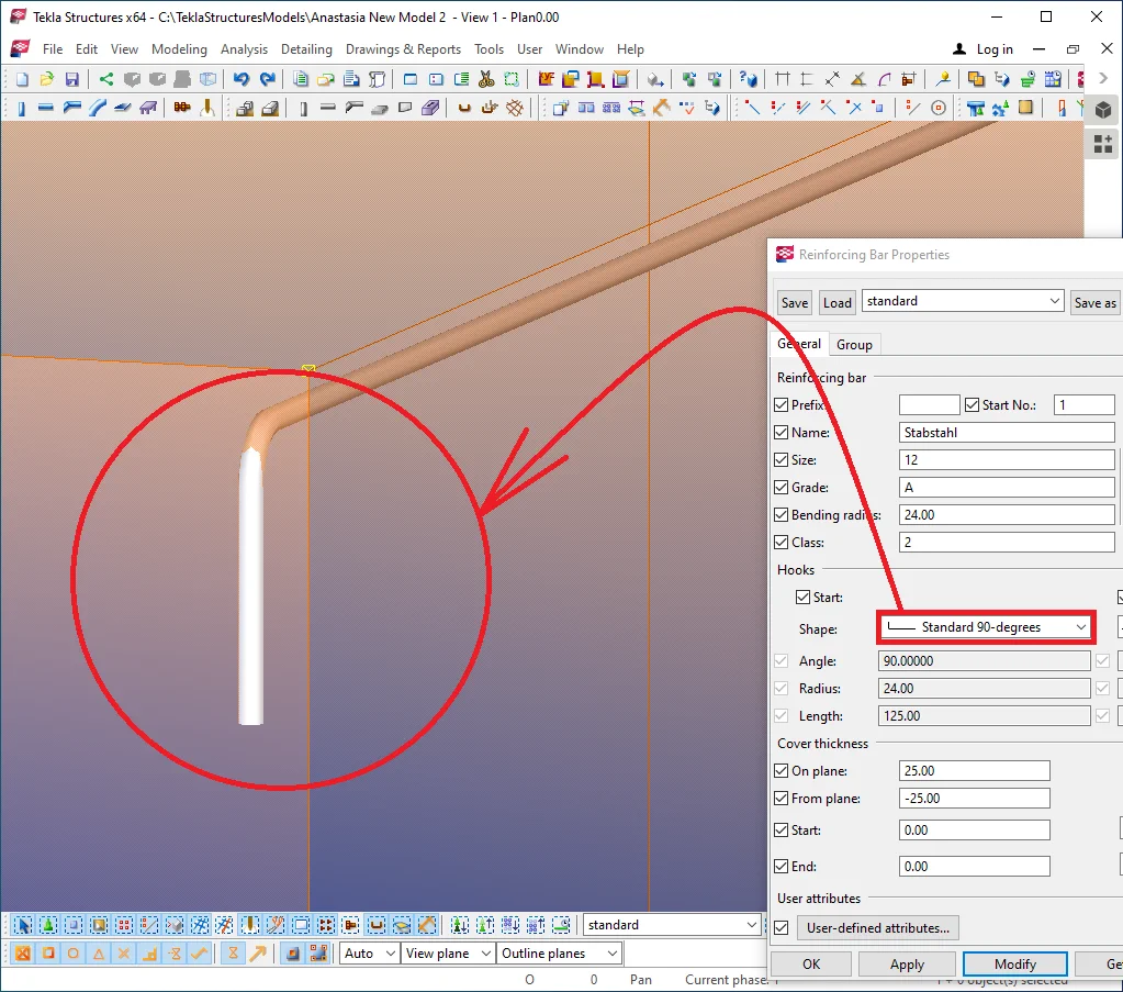
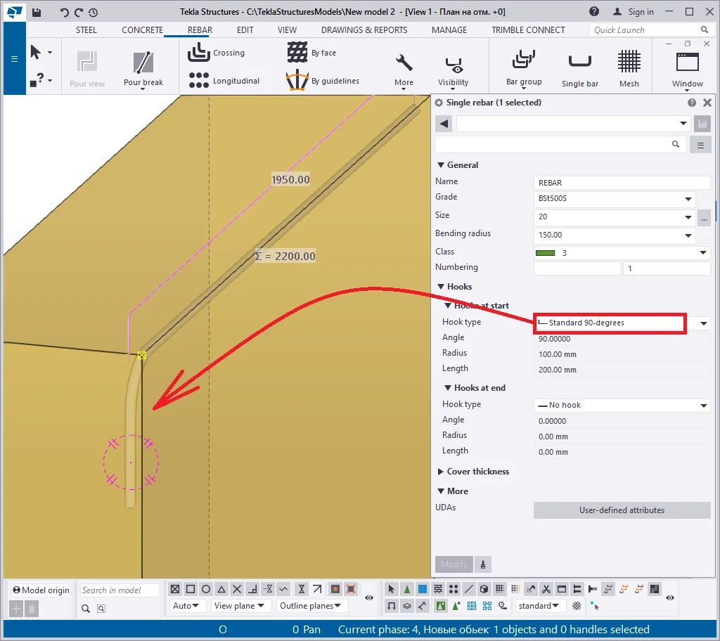
As you can see, the reinforcing bar was extended and cambered at its starting point at the standard value indicated in the respective parameters section. The standard values for hooks are defined by the localization package and do not need to be introduced manually.
Also, the values of parameters are automatically changed upon the size
Unfortunately, it is not possible to realign the reinforcing bar hooks in the opposite direction. Thus only creating a reinforcing bar defined by opposite configurations allows directing the hooks outside the concrete object's body.
Let's exercise the above by creating one more reinforcing bar.
Though the settings for creating the reinforcing bars are the same, the users can not control the direction of the hooks' ends. The reason for this is that the direction is defined by the local coordinates of the reinforcing bar.
|
|
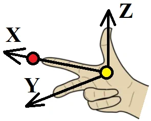
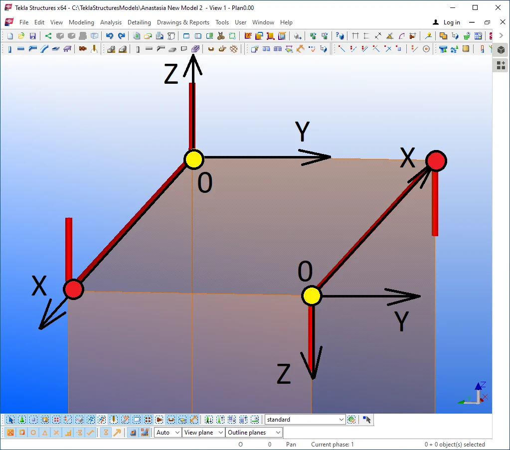
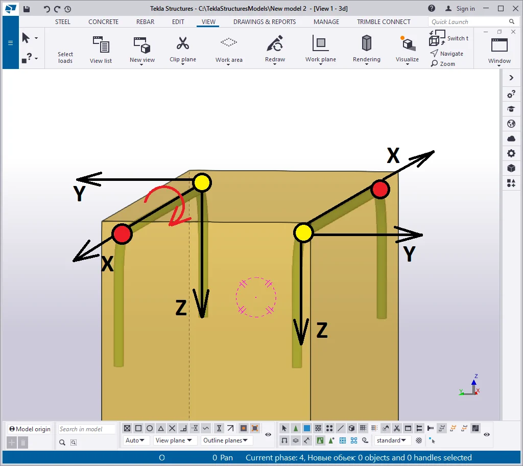
Imagine a coordinate system defined by the axes X, Y, Z. The starting point of the reinforcing bar is the coordinate system origin. The second (endpoint) indicates the direction of the X-axis and the reinforcing bar. The other axes' directions are easily determined by the "right-hand rule". By this rule, the right hand's first finger indicates the X-axis direction, the thumb pulled at 90 degrees indicates the Z-axis direction, and the middle finger bent to 90 degrees into the palm defines the Y-axis direction.
|
Thus you can see that the reinforcing hooks are every time co-directed
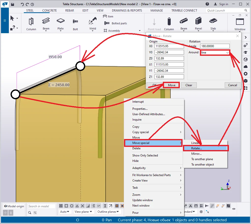
If you need to control the direction of the hooks, use the "Move Special"/"Rotate" tool. Select the reinforcing bar and in the right-click menu, go to the "Move Special"/"Rotate" tool. Indicate the rotation line by two points (the starting and endpoint of the bar), and press the "Move" button.

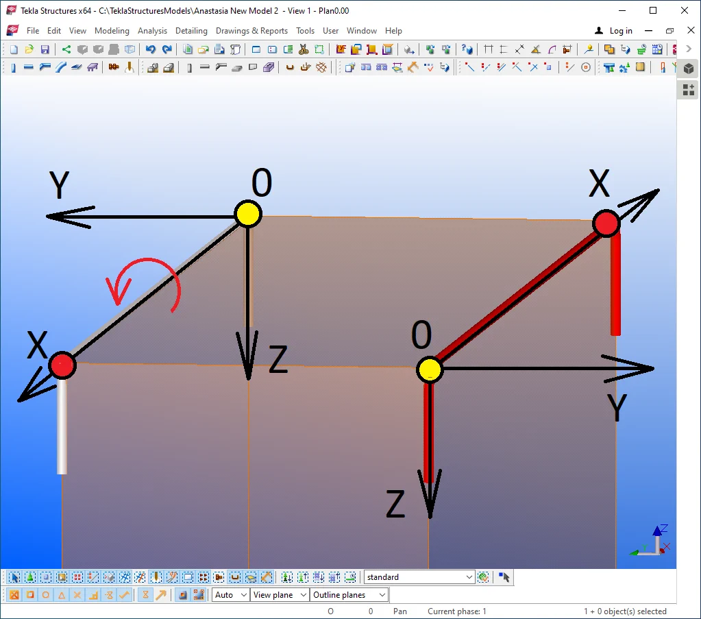
Let's investigate the result: rotating the reinforcing bar caused the rotation of its coordinate system, thus the hooks became uniaxial with the Z-axis, at the same time the direction of the Z-axis is opposite to the respective of the reinforcing bar.
Note that the offset "On plane" and "From plane" values are still moving the reinforcing bar along the axes. Thus one and the same reinforcing bar created from left-to-right differs from the one created from right-to-left by the configurations to be applied to assure the similarity. Every time consider the direction of the axes when modeling structures.
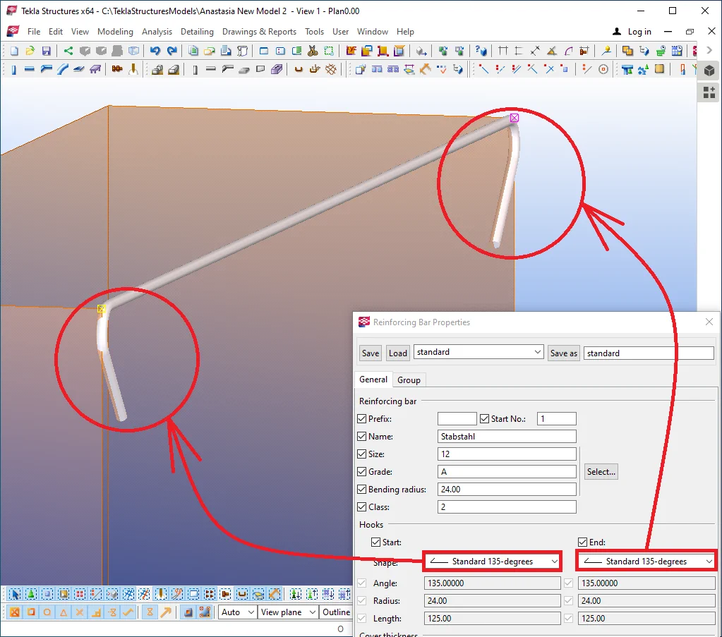
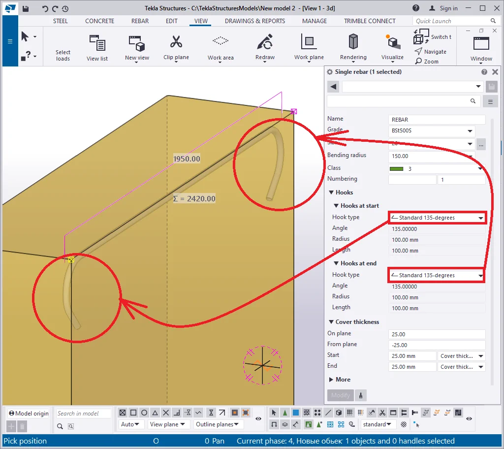
Delete the second reinforcing bar. Get back to the "Single rebar Properties" menu and configure the hooks type to "Standard -135 degrees". Such a type of hook is not suitable for all the reinforcing bar grades and sizes. Thus it might happen that some of the hook types do not work out. You may toggle between the other "Grade" and "Size" options to create the very hook type required.
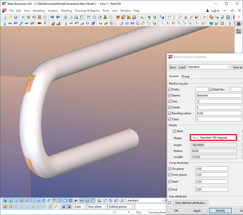
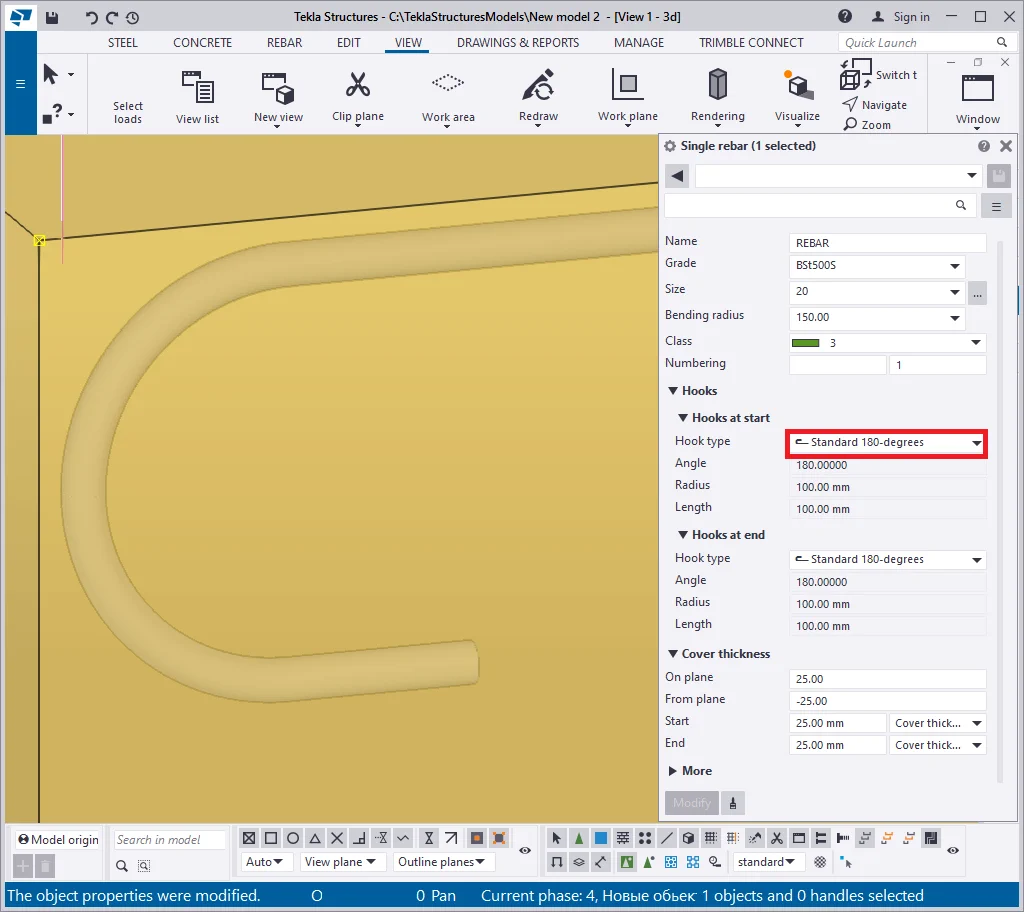
Switch the hook type to “Standard-180 degrees”.
Now switch to the "Custom hook" type. Now the "Angle",
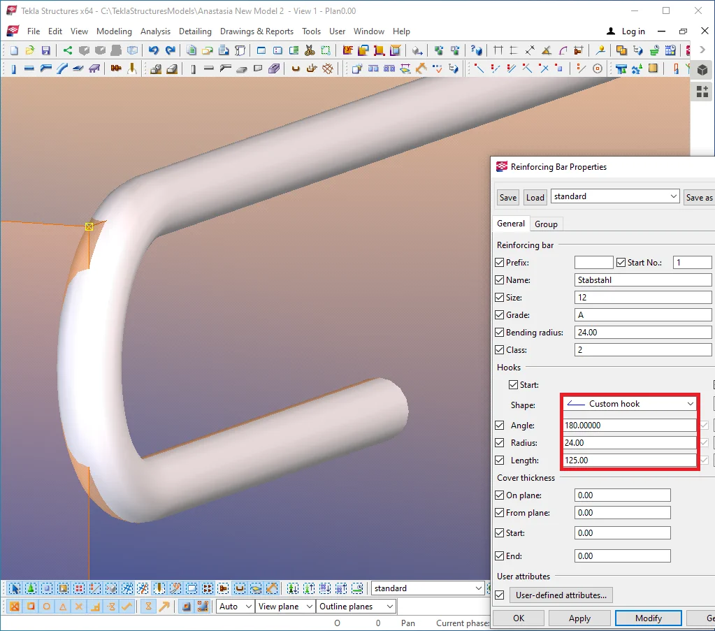
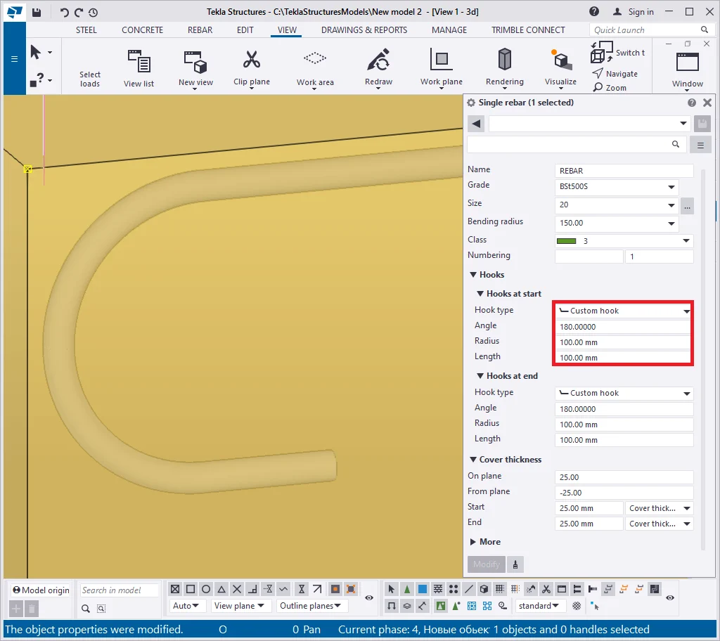
Now on the field values are not automatically set up by the TS, but are to be manually configured by the user to create the required shape of the hook. Let's change the field values and investigate the result.

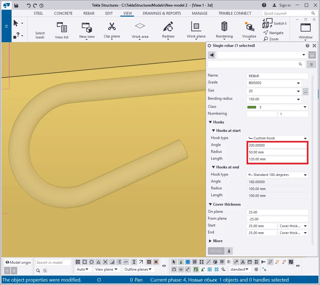
You may not use the "Hook" tools but directly create a reinforcing
The “Bending radius field” defines the bending radius of reinforcing bars.
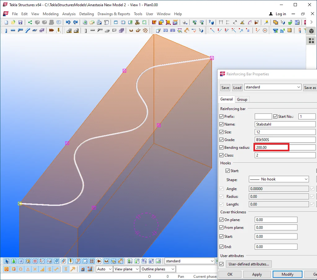
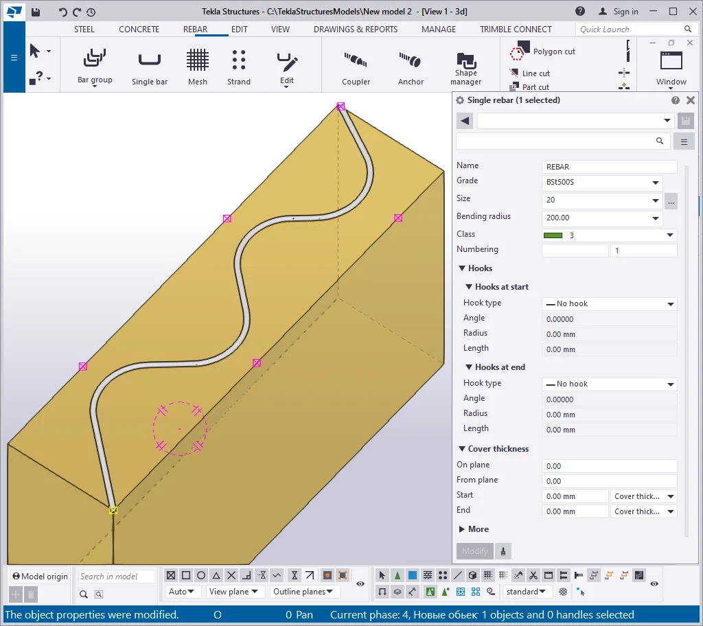
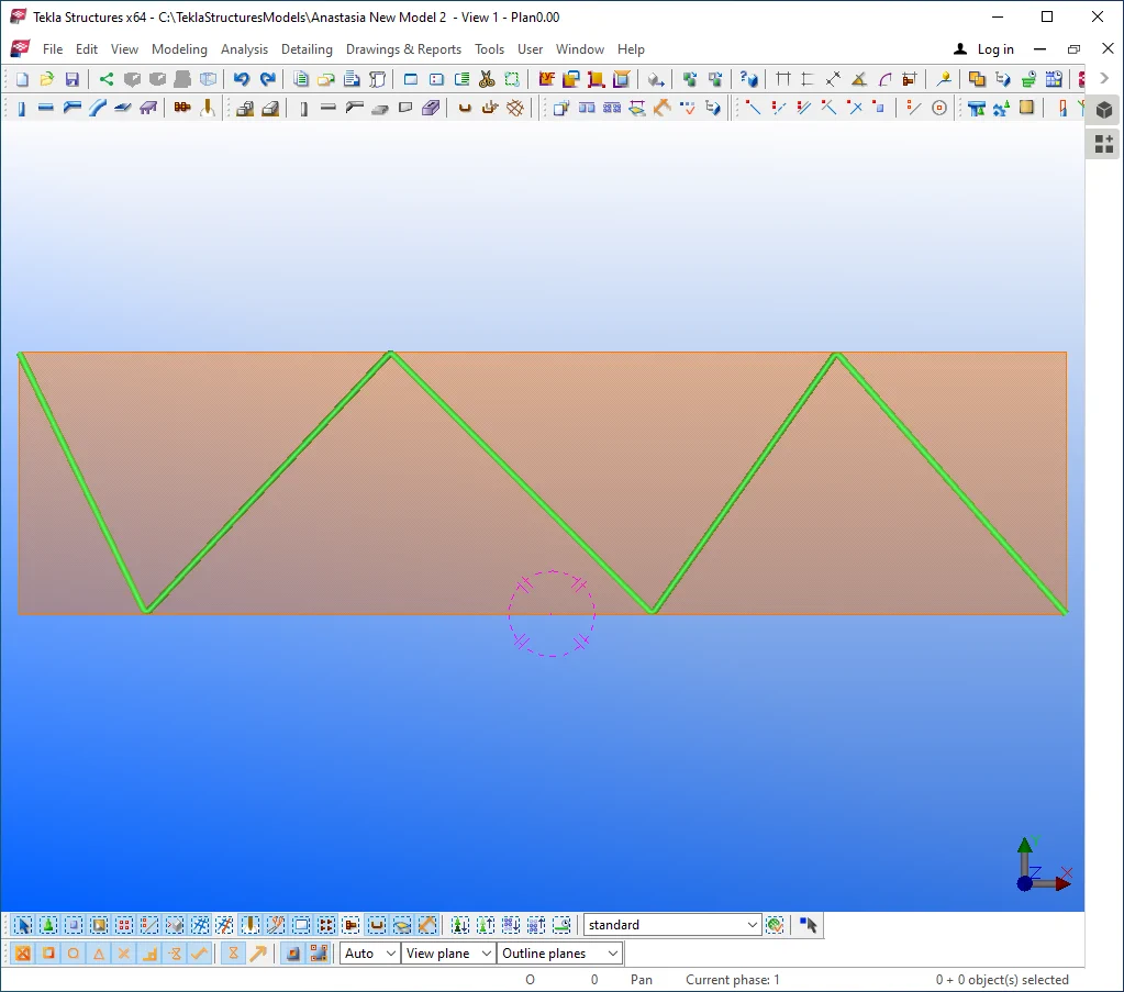
To understand the functionality of this tool, create a reinforcing bar not by a straight line, but by indicating the intermediate points, forming a broken line. Follow the below example:
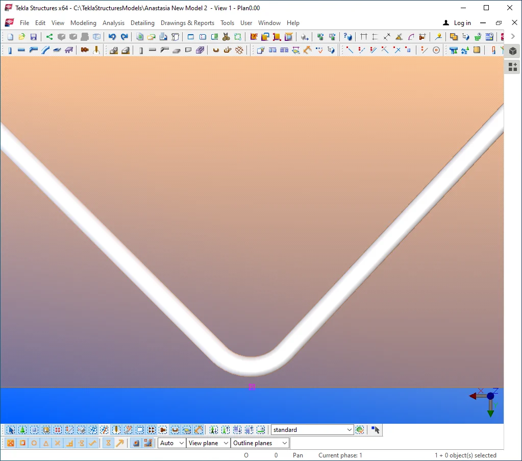
Maximizing the reinforcing bar to its inflection point, you can see its bending part. Exactly its bending radius defines the inflection shape.
Do not forget when finalizing indicating the reinforcing bar points to
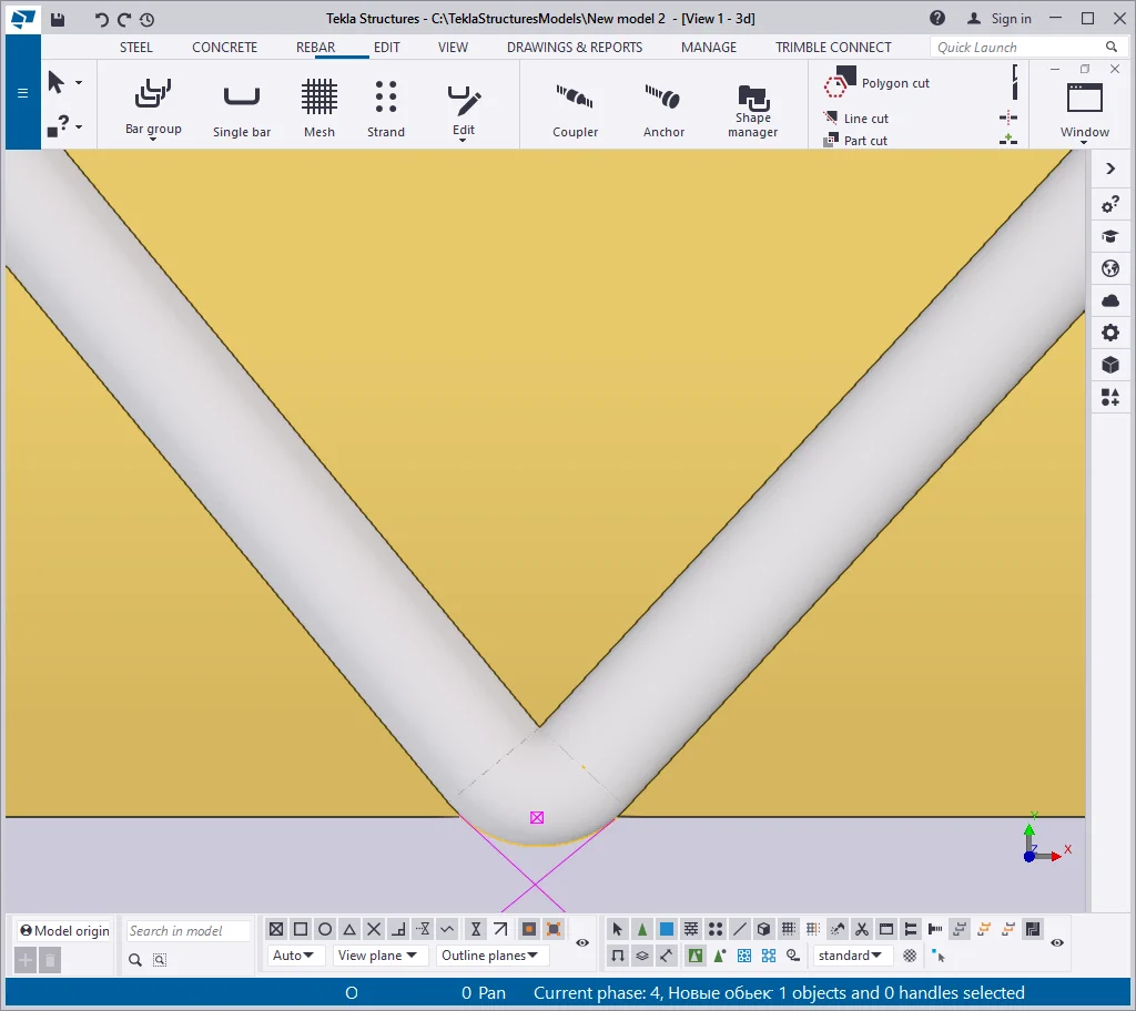
Set out the "Bending radius" value at 200 mm. Thus the shape
Now set out the "Bending radius" value to an extreme value, for example, 1000mm. Considering that the beam's thickness is 500 mm, it is not possible to execute the inflection greater than the distance between neighbor points.
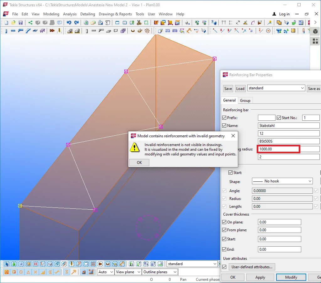
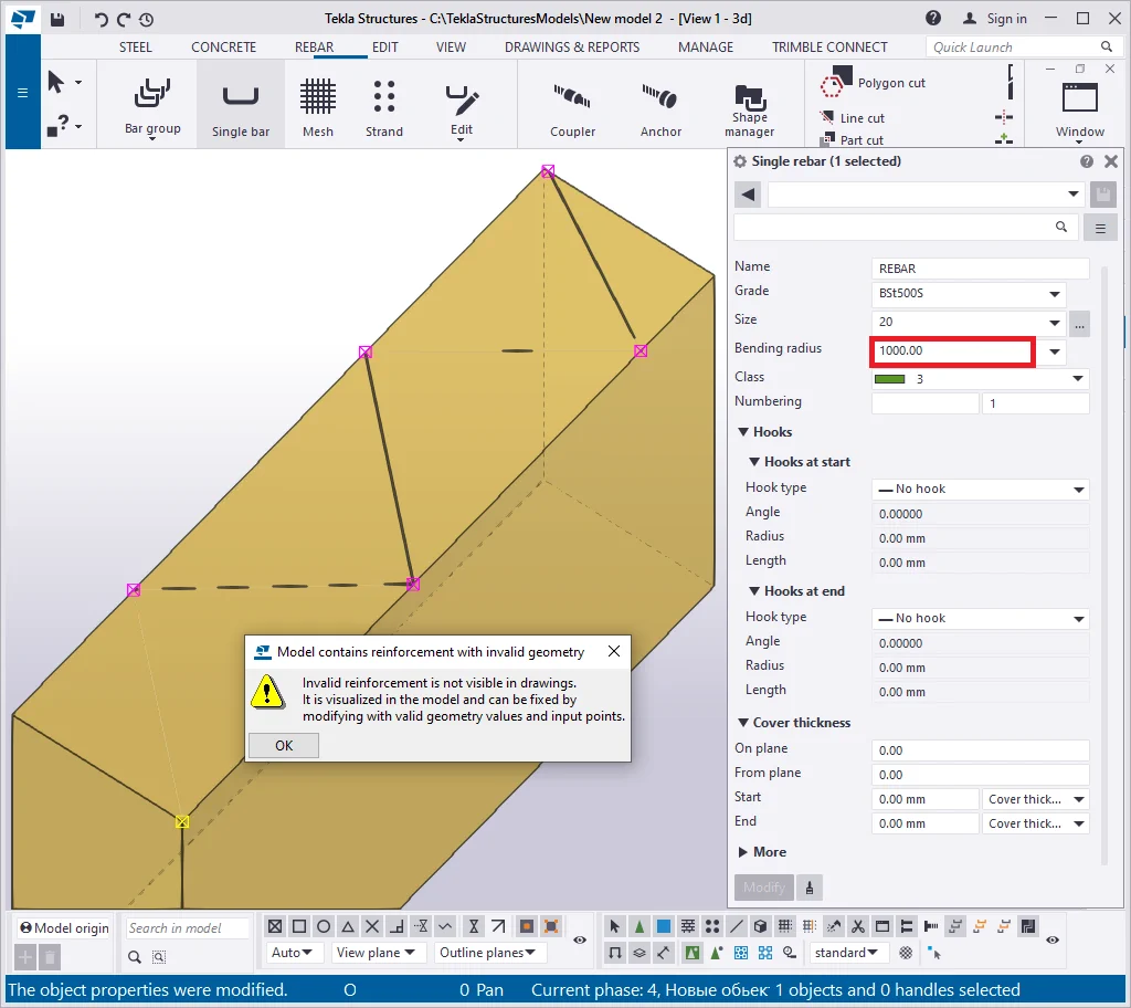
As you can see from the above, the reinforcing bar is rendered in a wrong way, and the TS alerts about the error. Set the "Bending radius" value equal to 0.

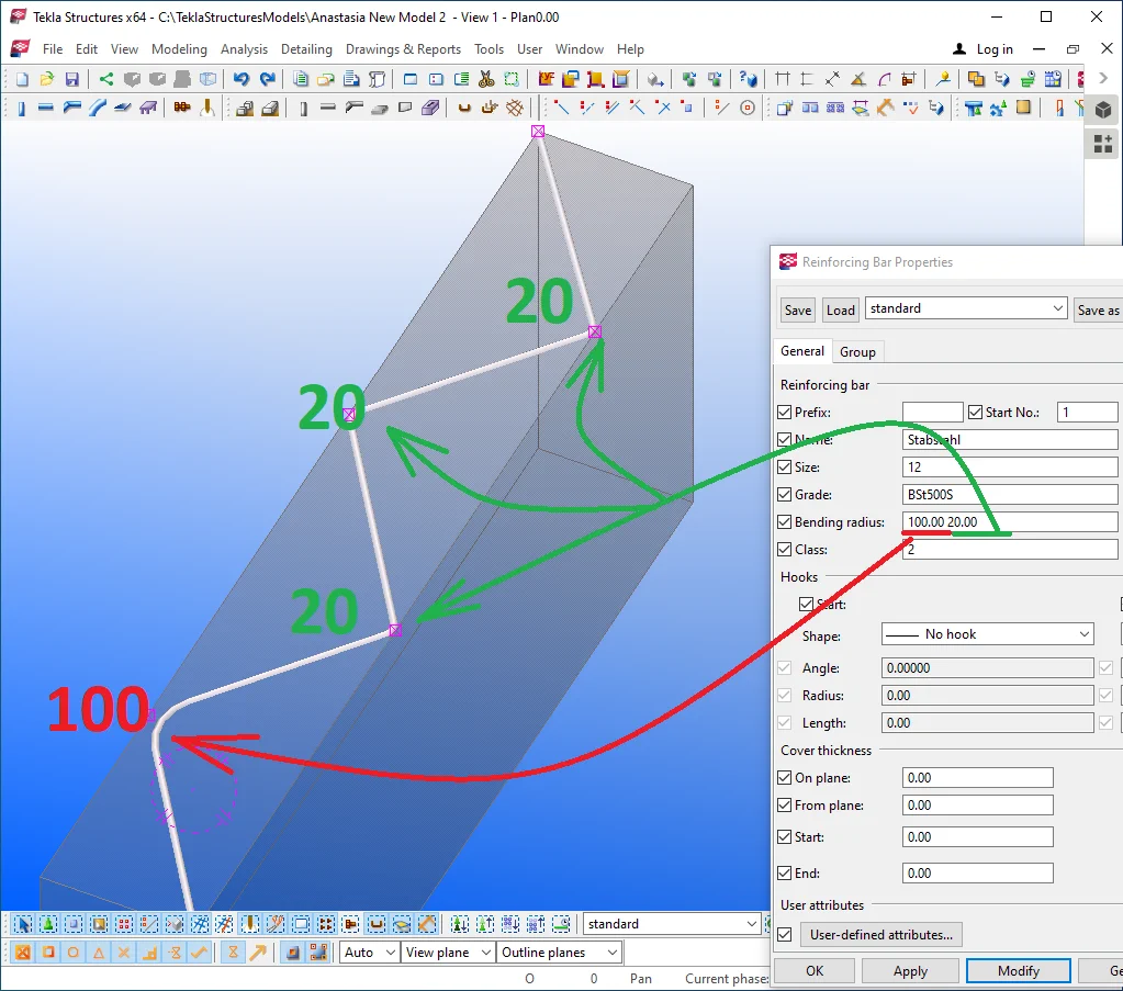
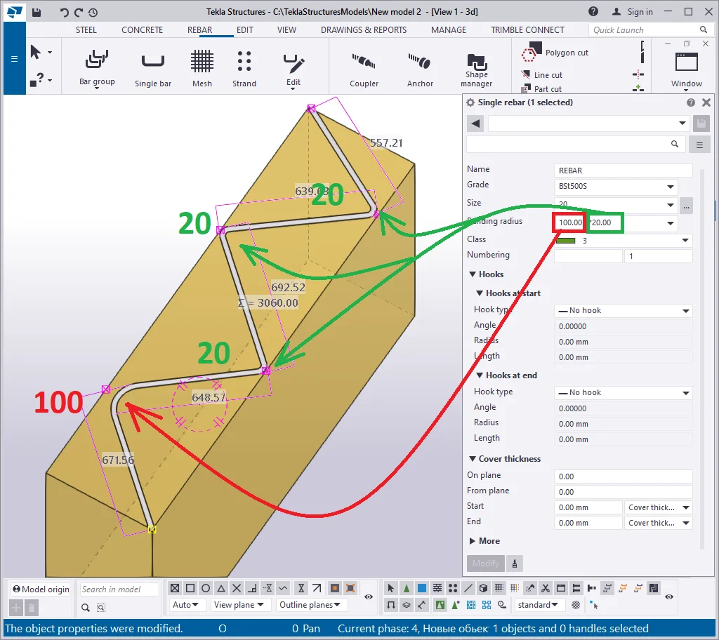
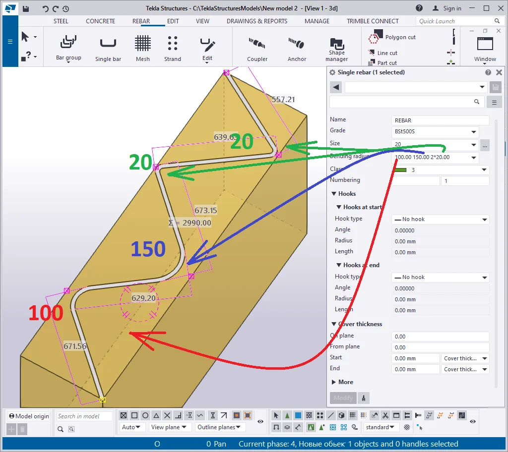
The "Bending radius" value refers to all the inflection points simultaneously. To separately define the "Bending radius" value at every inflection point, it is important to know the starting and the endpoints of the reinforcing bar.
Similar to the steel objects, a reinforcing bar object is defined by a
Thus the "Bending radius" values are indicated in a line by a "Space" separator in the direction from the starting point to the endpoint. The starting and the endpoints are not described by any bending radius.
Let's indicate the bending radius of the first inflection equal to
Now set out the "Bending radius" as “ 100 150 20 ”. In this case, the first inflection radius will be 100 mm, the second one equal to 150 mm, and the third and the following ones of 20mm.
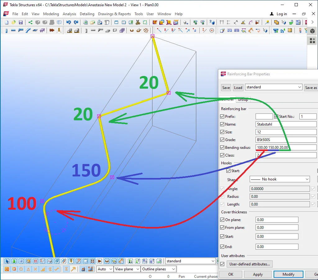
Exercise on your own setting out various "Bending radius" values.
Note that even curvilinear reinforcing bars may contain hooks. However,

The "User-defined attributes" are not standard parameters and are added or removed by the users. As general, the companies developing the localization packages add to the user-defined attributes the parameters considering the local regulations.


We will investigate in detail the "User-defined "attributes when reaching the "Reports and statements" chapter, as basically, these parameters do not influence modeling structures.