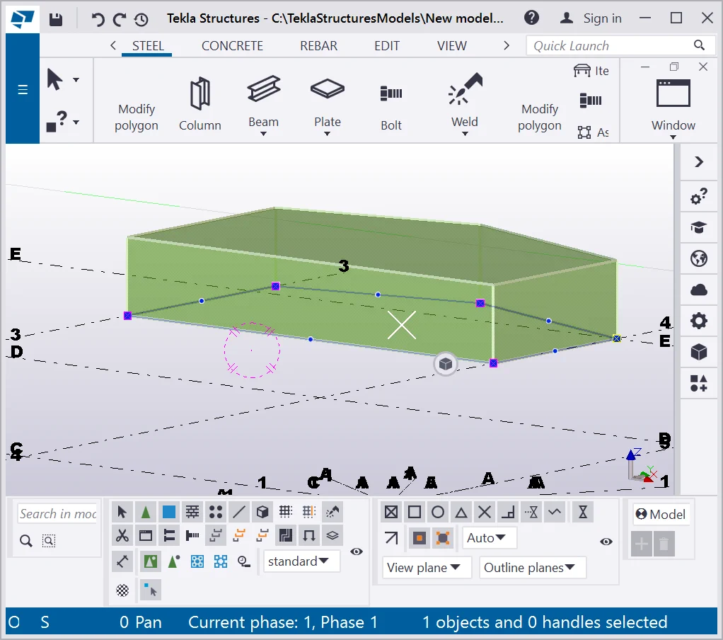
By means of the “Contour plate” tool, it is possible to create a steel plate object in the model. Basically, a steel plate is just an object with a multangular shape, characterized by a definite thickness value.
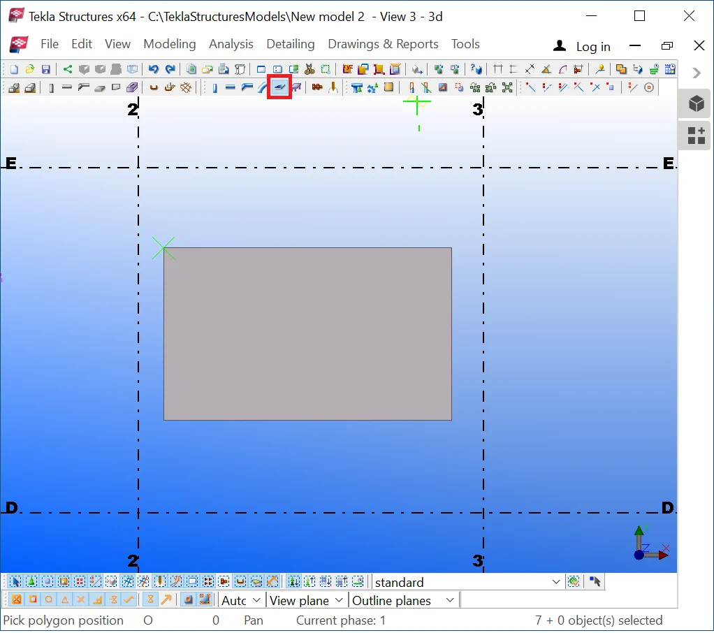
Make sure that the snapping tool
 - “Snap to any position”, is activated, as it allows creating
any construction geometry object at the blank space. By pressing the Ctrl+P
hotkey combination, go to the view plane.
- “Snap to any position”, is activated, as it allows creating
any construction geometry object at the blank space. By pressing the Ctrl+P
hotkey combination, go to the view plane.
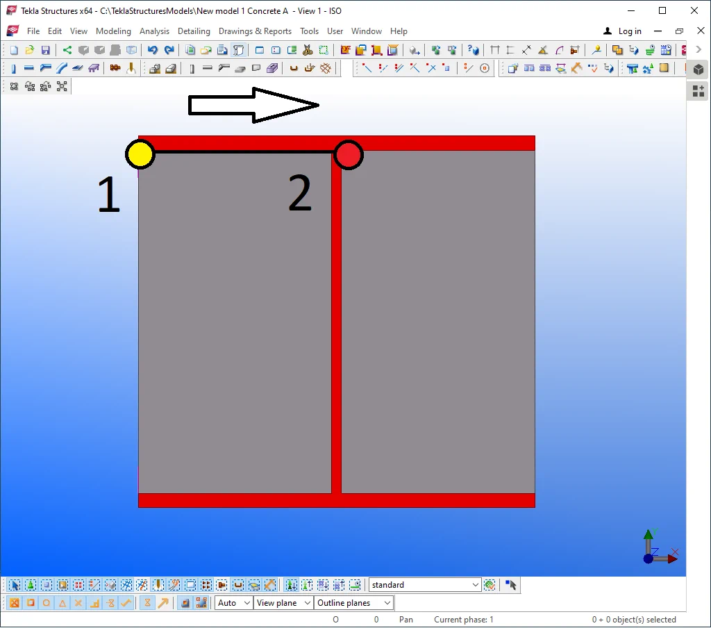
Method one (1): defining the points of a contour plate by using PC mouse
The algorithm for creating a contour plate is as follows:
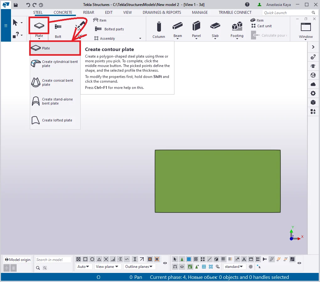
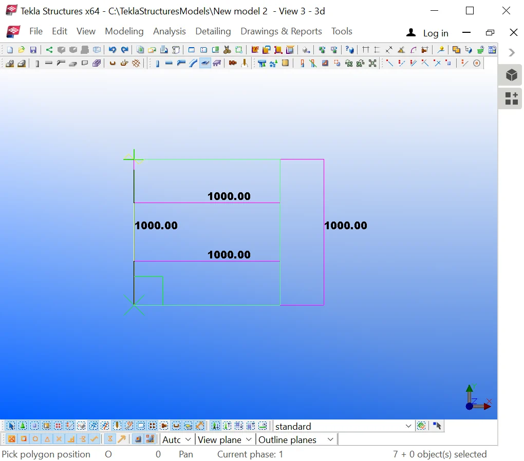
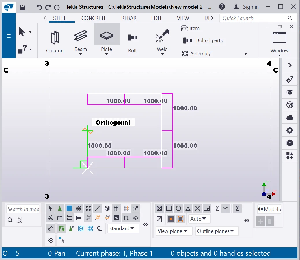
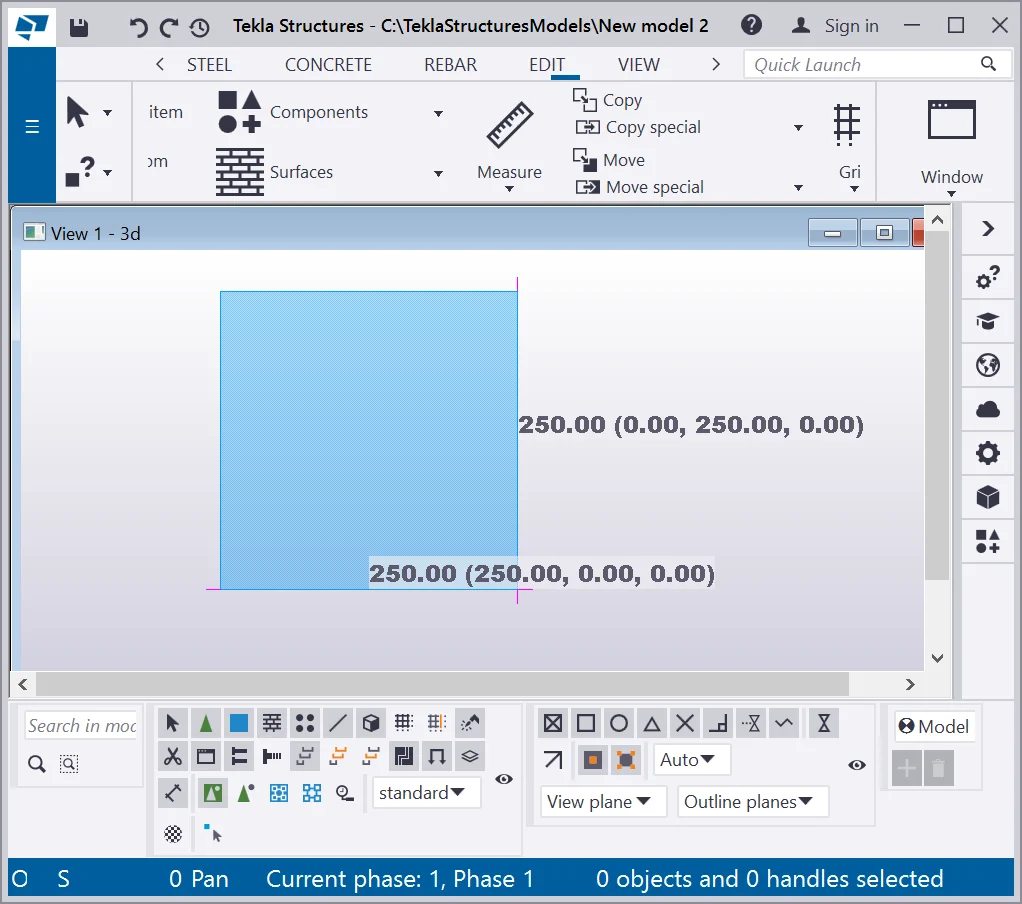
If it is required to create a plate of definite dimensions and of a definite shape, then it is necessary to identify the directions of its polygon sides and introduce the length values of the sides. Create a square shape plate with a side length of 1000 mm.
Method two (2): creating a contour plate by introducing the values of
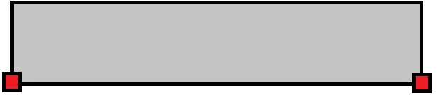
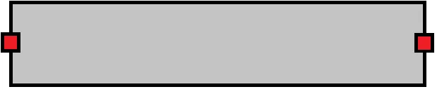
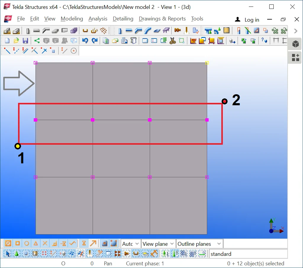
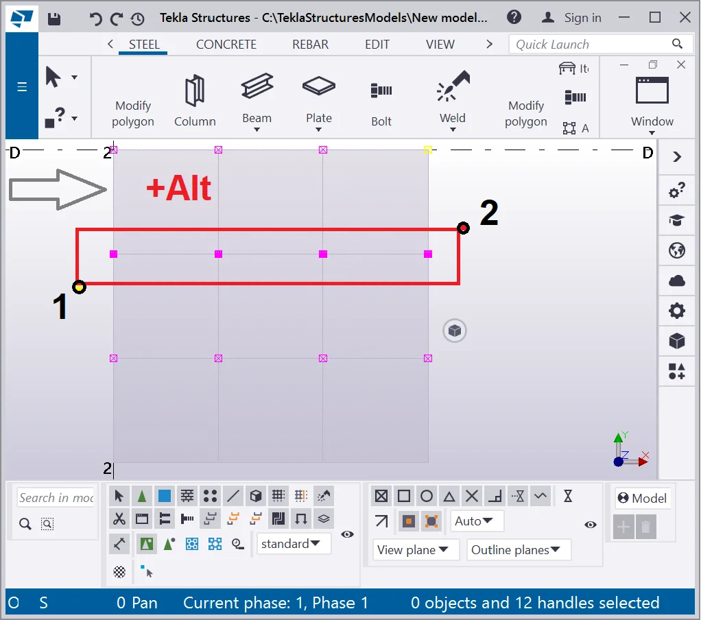
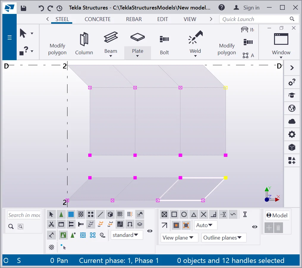
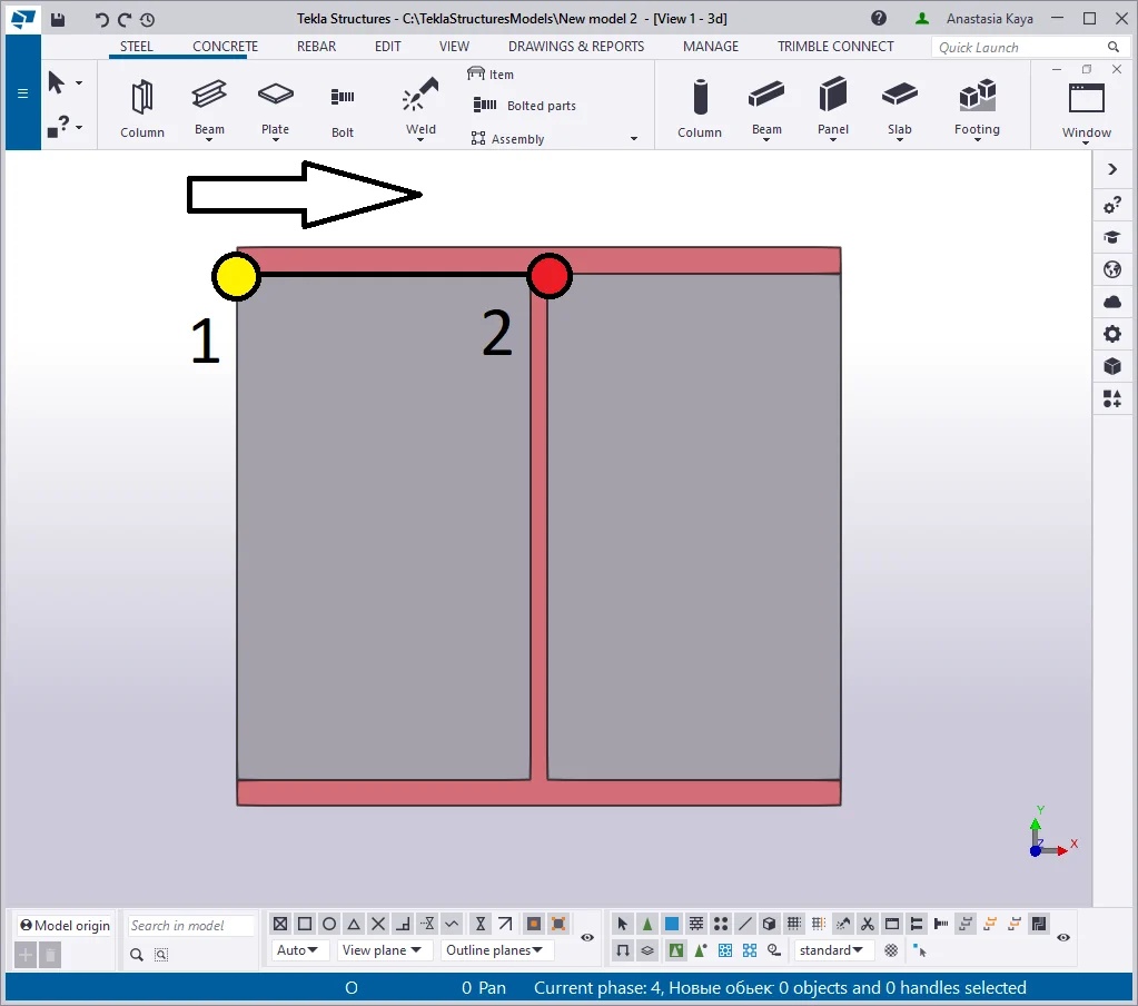
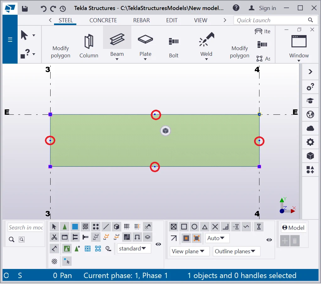
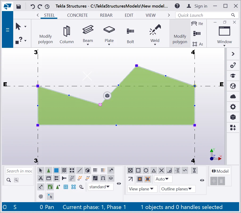
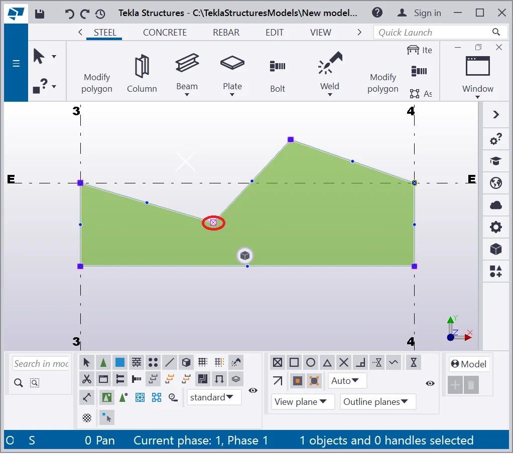
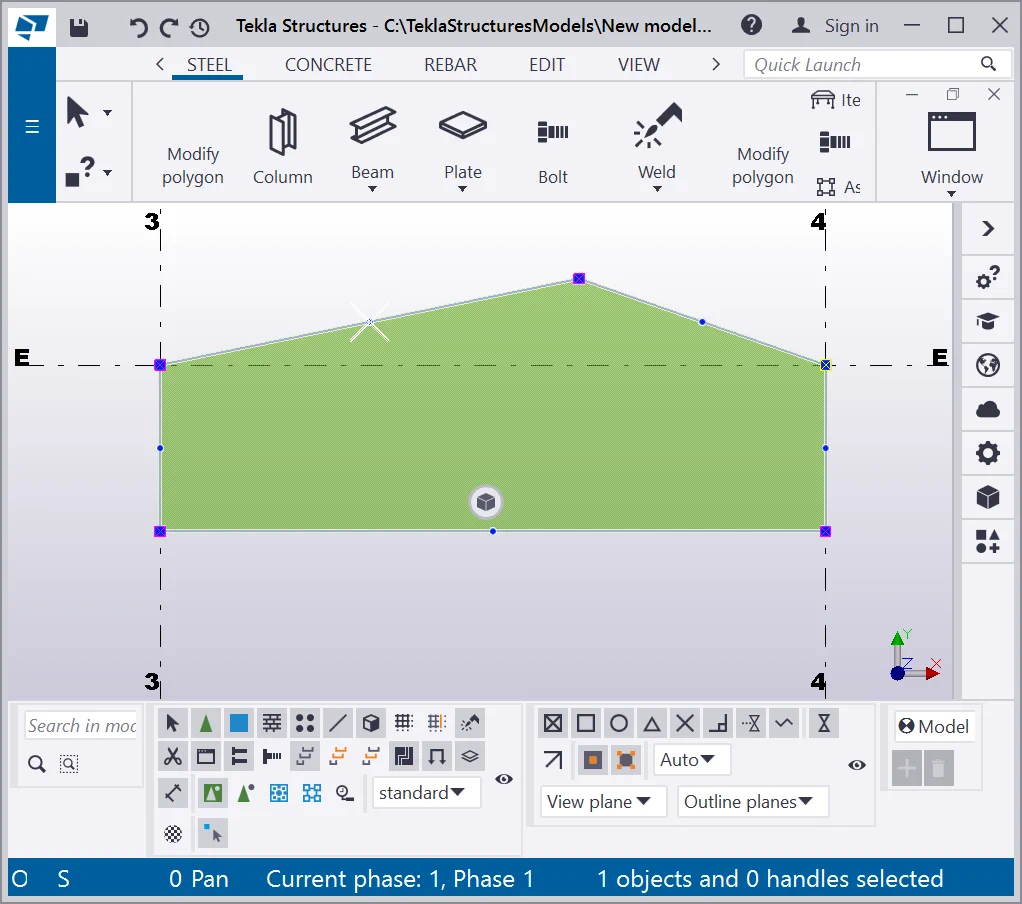
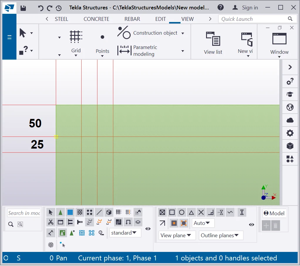
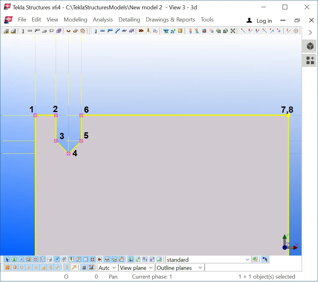
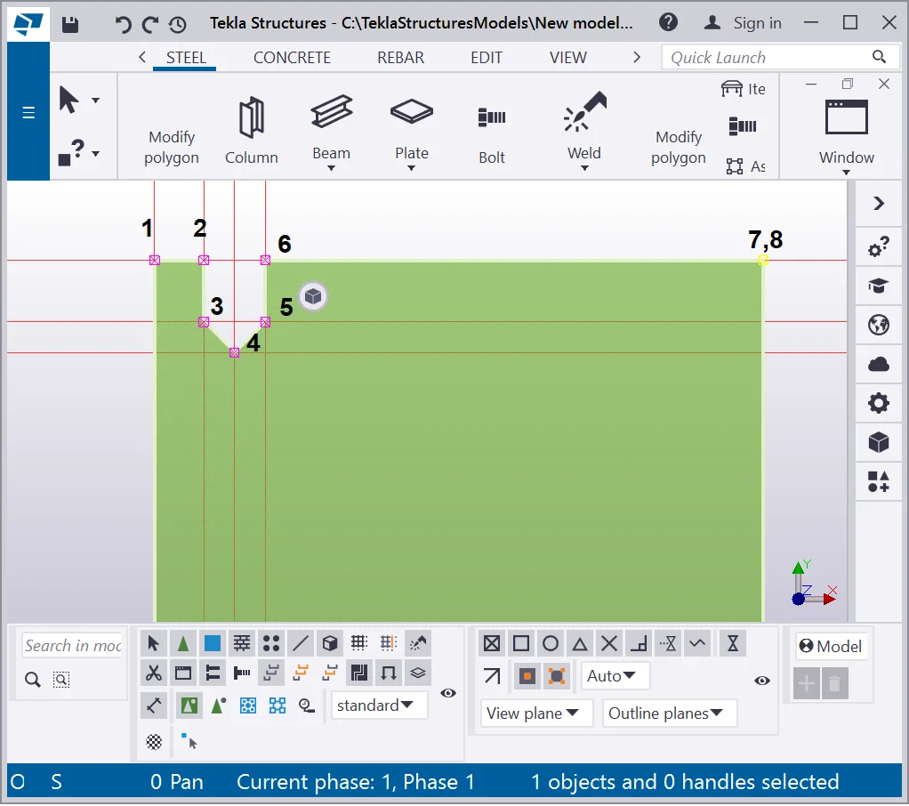
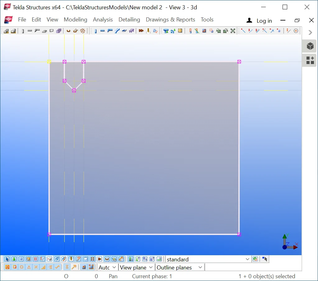
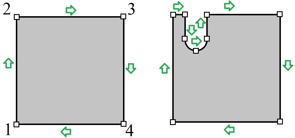
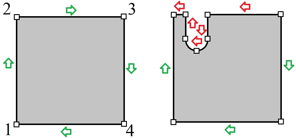
Entering coordinates using the “Ctrl” key allows excluding several points from the trajectory defining the plate’s shape. Refer to the below pictures:
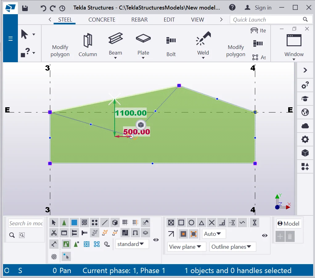
Points marked in red do not make part of the contour plate’s shape and were created by utilizing the “Ctrl” key. Thus it is possible to create contour plates of various shapes without any recourse to a complimentary drawing up.
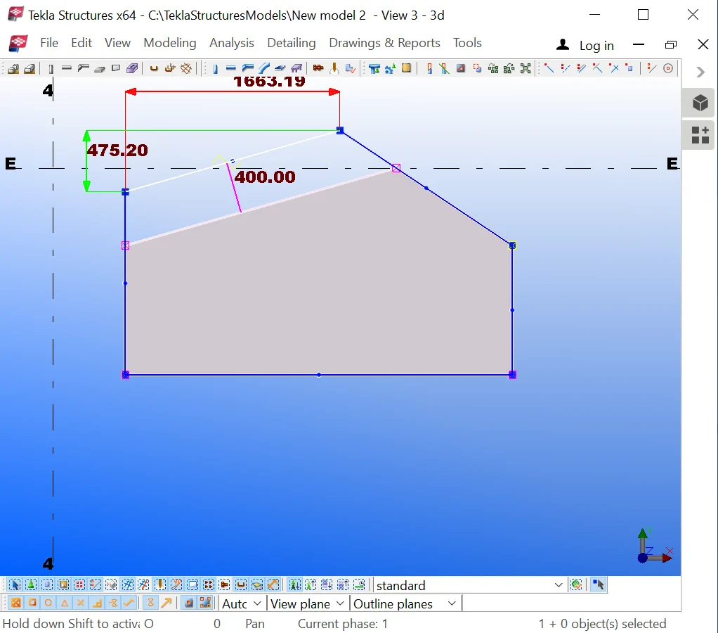
The 1st method: setting coordinates of the contour plates of a complex
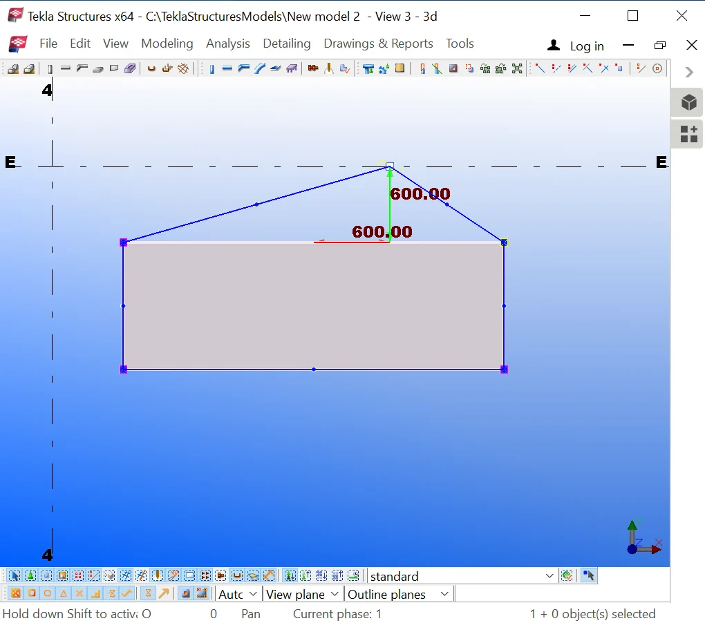
Note, if you set the coordinates of the contour plate by using the mouse cursor, then hold on the “Ctrl” key pressed prior to creating an intermediary point with a left-click at the view plane. Further, release the “Ctrl” key and continue allocating the points of the contour plate. It is important to mention that TS offers the values of step dependent on the scale grade. Maximizing the object makes the value of the step smaller, and vice versa.
The 2nd method: setting values of the contour plate’s sides by means
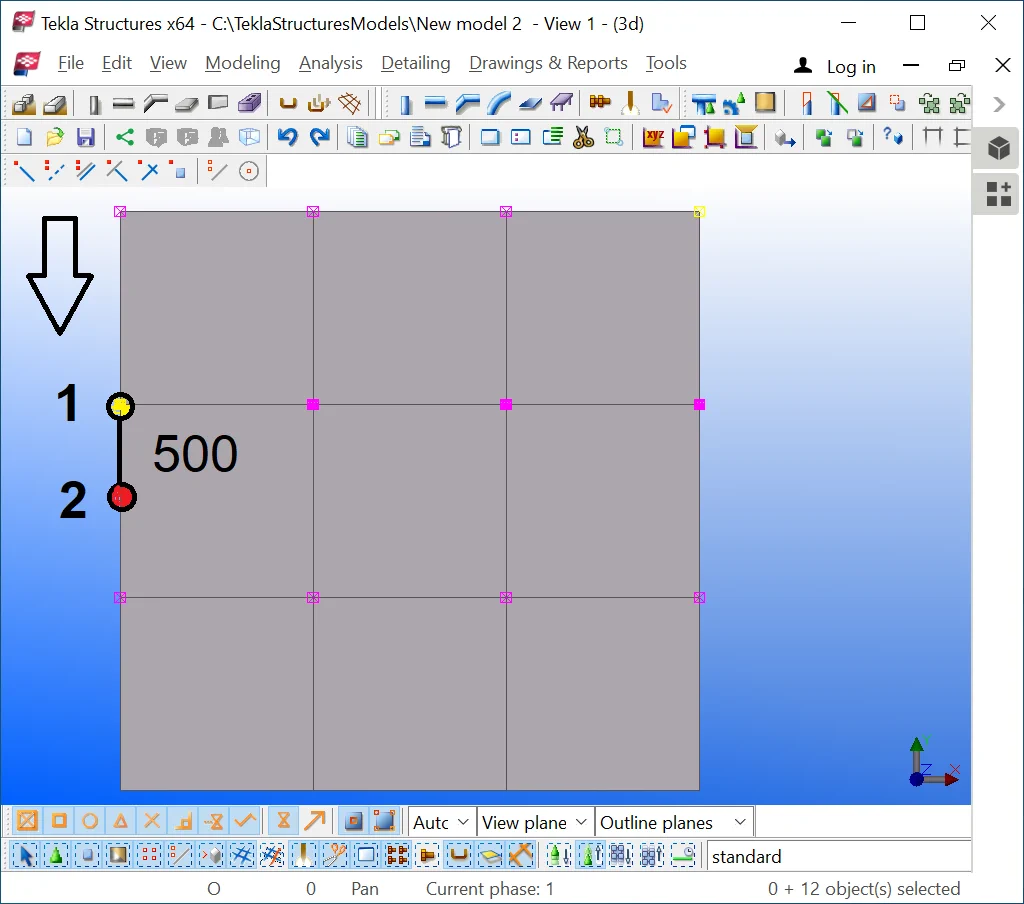
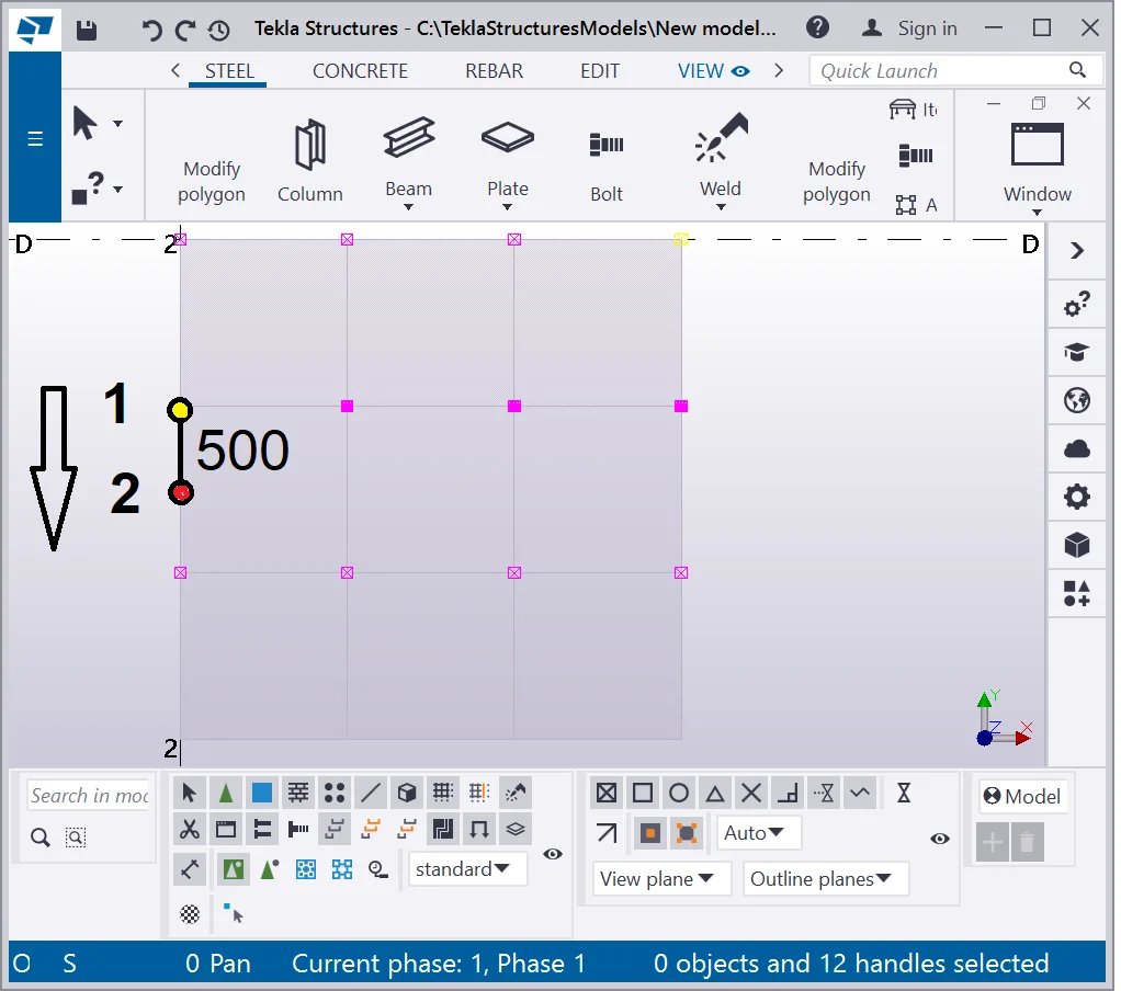
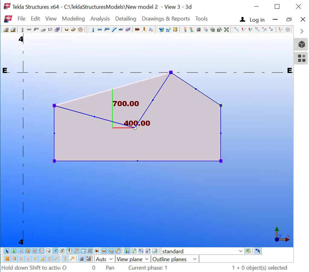
If you enter contour plate coordinates from the keyboard, then firstly type in the value of the side length and subsequently press the "Ctrl" key prior to confirming the operation by the "Enter" key.
Exercise the methods described above.
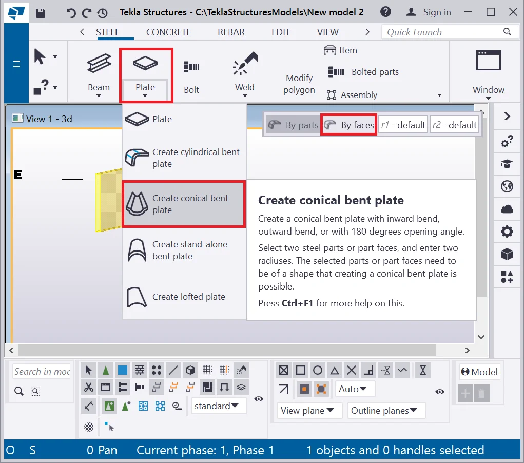
The “Create the conical bent plate” tool allows drawing plates
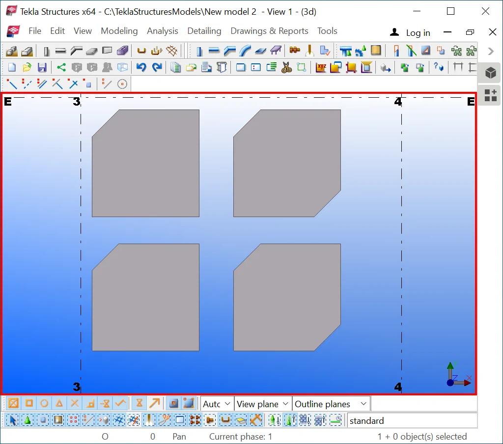
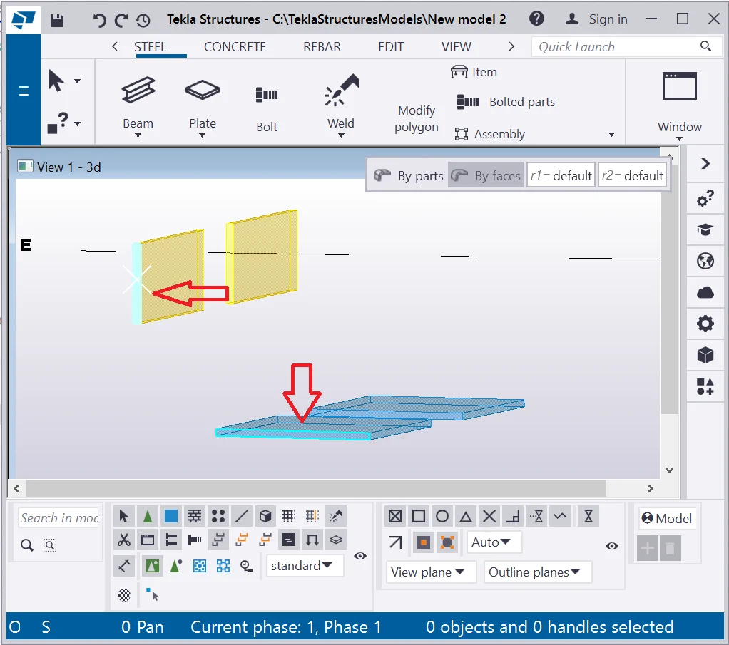
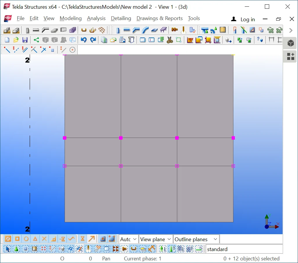
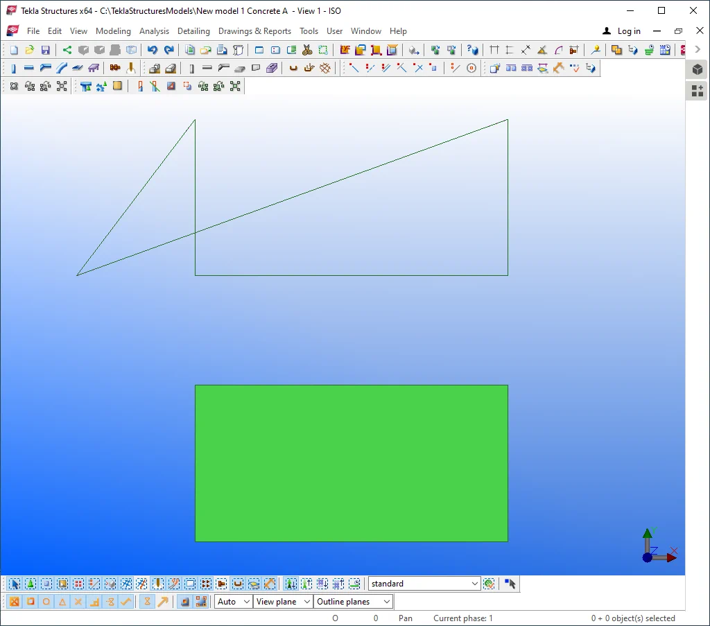
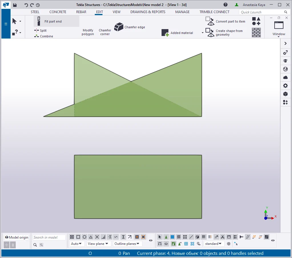
To examine the tool, create two perpendicular plates as practiced in the
Present Tekla Structures version is not available on the “ Create the conical bent plate” tool

The initial test model is shown below:
Present Tekla Structures version is not available on the “ Create the conical bent plate” tool

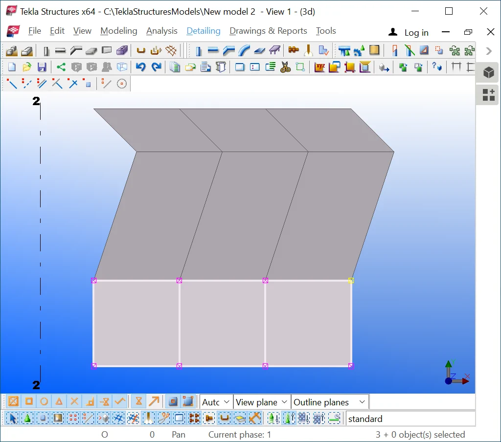
Move the perpendicular by the Z-axis plate plate vertically at 150 mm.
Present Tekla Structures version is not available on the “ Create the conical bent plate” tool

The “Create the conical bent plate” tool works bilaterally:
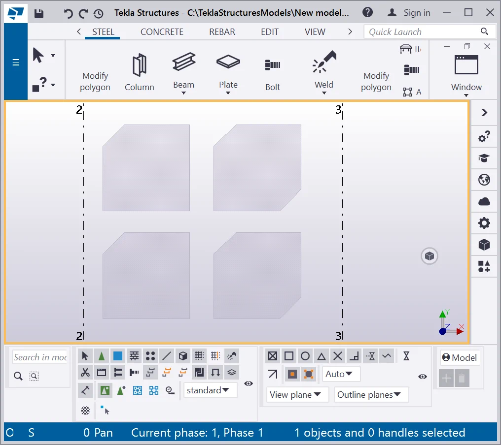
For a comparative analysis, let’s create one more analogical
Present Tekla Structures version is not available on the “ Create the conical bent plate” tool

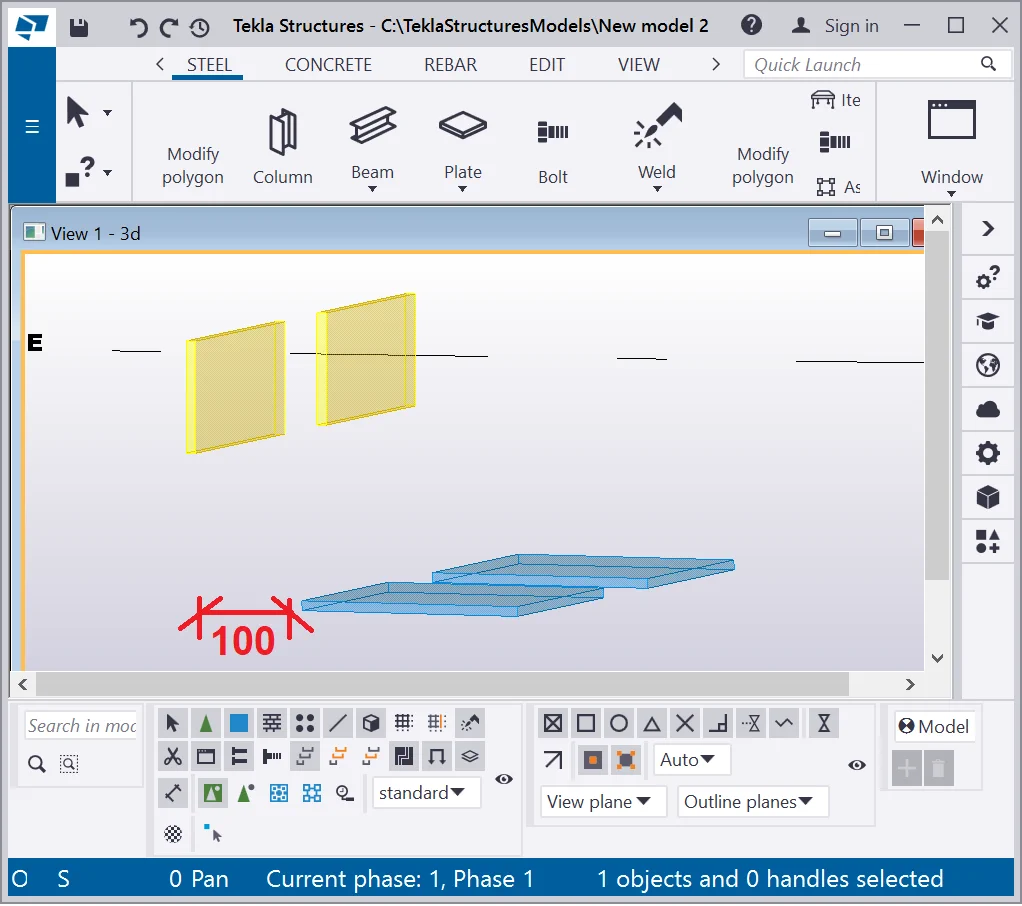
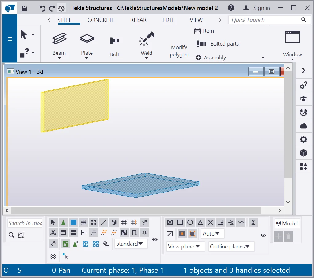
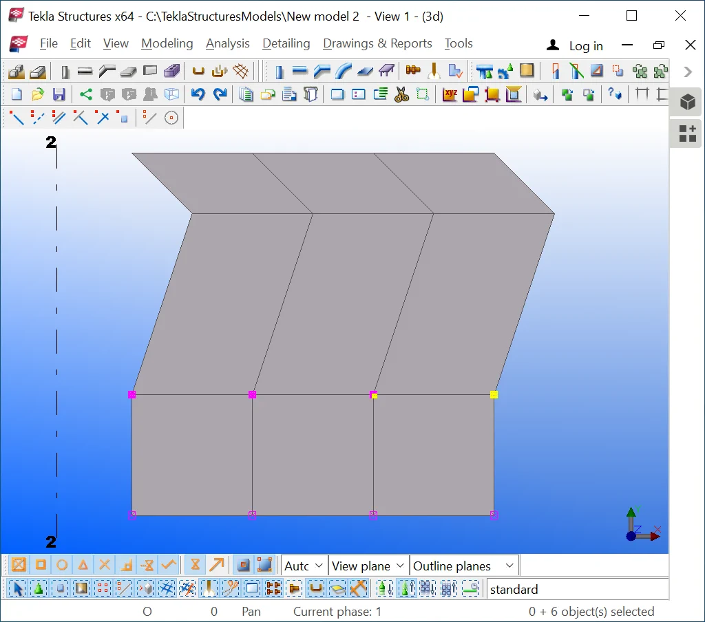
Select yellow plates and move them orthogonally aside at 100mm from the
Present Tekla Structures version is not available on the “ Create the conical bent plate” tool
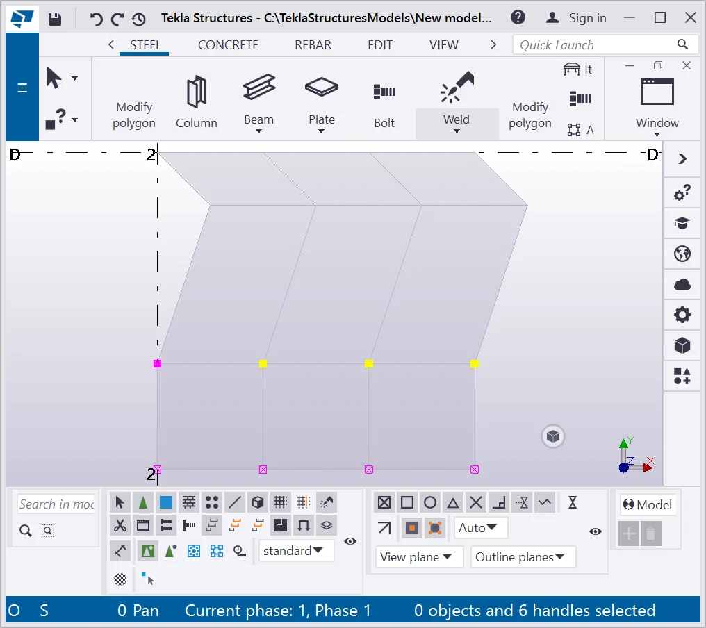
Go to the “Plate” tool drop-down menu and select the “Create conical bent plate” tool, and indicate the “By faces” snapping type.
Present Tekla Structures version is not available on the “ Create the conical bent plate” tool
Click on the faces of the plates:
Present Tekla Structures version is not available on the “ Create the conical bent plate” tool
If you carried out all the operations correctly, then your results are
Present Tekla Structures version is not available on the “ Create the conical bent plate” tool

Let’s examine the “Create the conical bent plate” tool
Present Tekla Structures version is not available on the “ Create the conical bent plate” tool
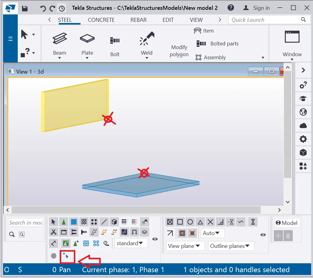
Activate the “Direct modification” tool and delete the points by using the “Delete” key, by referring to the below. Plates changed their shape to a triangle one.
Present Tekla Structures version is not available on the “ Create the conical bent plate” tool
Activate the “Create a conical bent plate” tool and indicate
Present Tekla Structures version is not available on the “ Create the conical bent plate” tool

Compare your results to the below:
Present Tekla Structures version is not available on the “ Create the conical bent plate” tool

This tool allows creating a plate of a complex shape, not derivable from
Present Tekla Structures version is not available on the “ Create stand-alone bent plate” tool
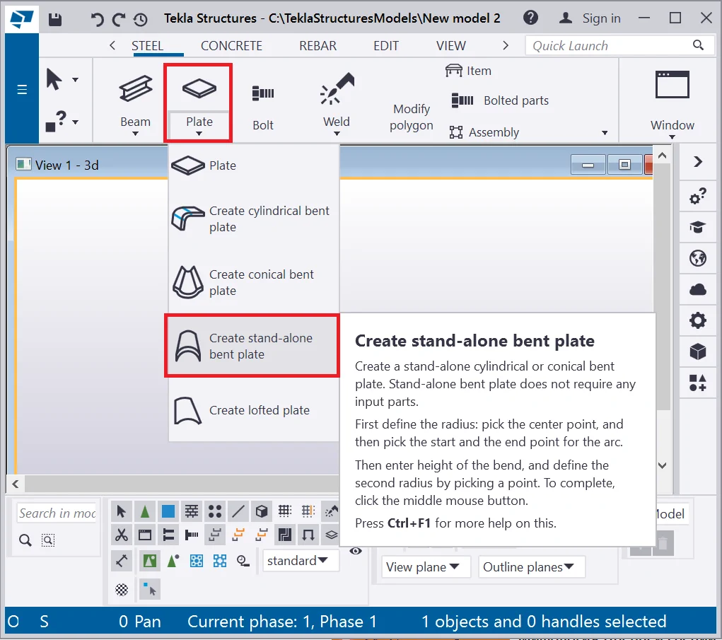
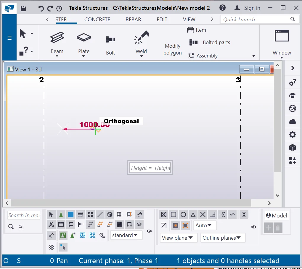
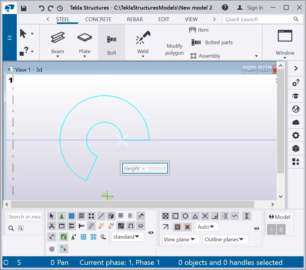
Enable the tool and specify the starting point, and the endpoint, at a
These points will outline the radius of a cone base.
Present Tekla Structures version is not available on the “ Create stand-alone bent plate” tool
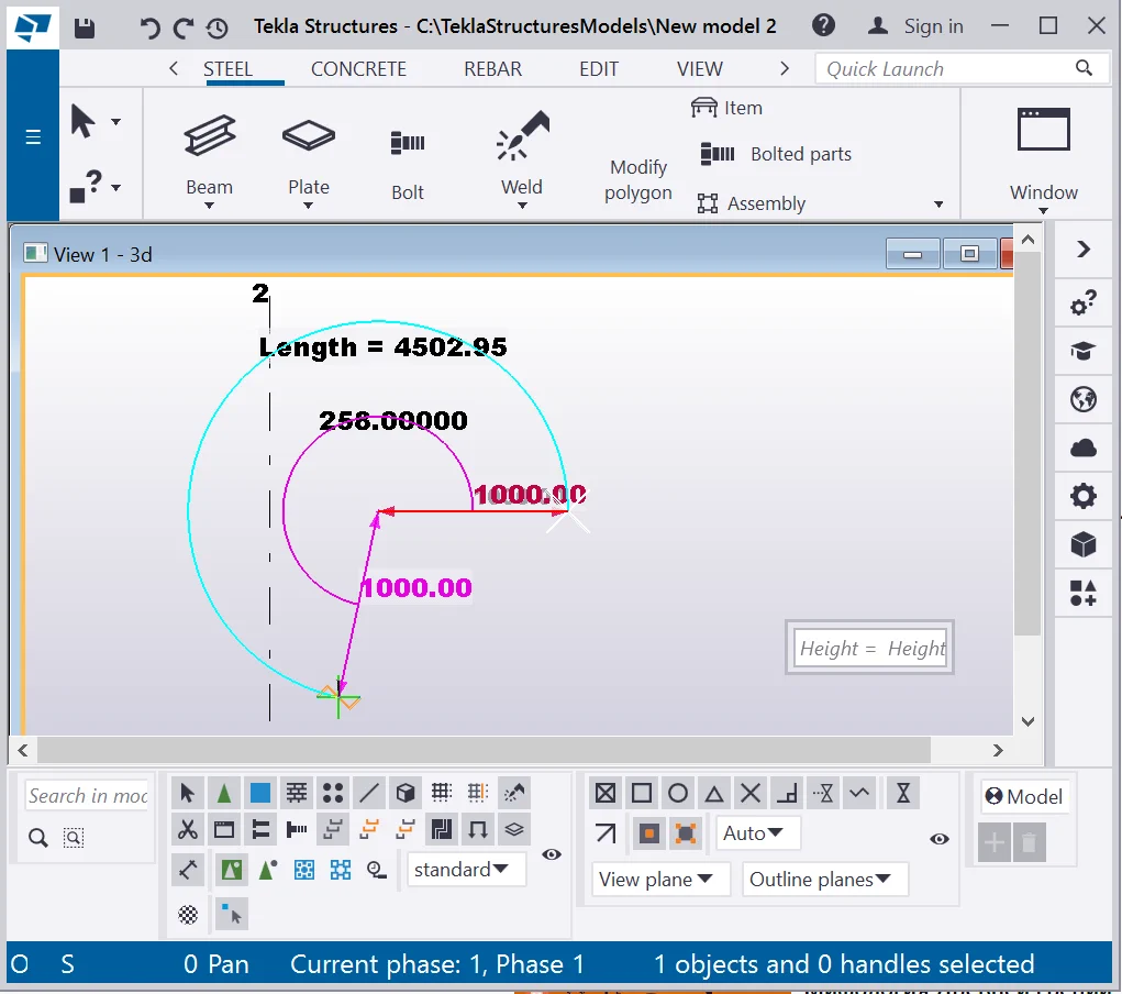
Indicate the minute of the object base arc, by pointing it out as shown
Present Tekla Structures version is not available on the “ Create stand-alone bent plate” tool
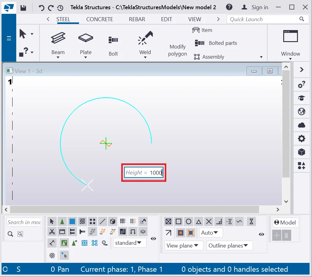
Type in the “Height” value of the object into the dialog box
Present Tekla Structures version is not available on the “ Create stand-alone bent plate” tool
Next step stands for determining and specifying the second radius -the
Present Tekla Structures version is not available on the “ Create stand-alone bent plate” tool

All specifications are done by the left-click.
Present Tekla Structures version is not available on the “ Create stand-alone bent plate” tool
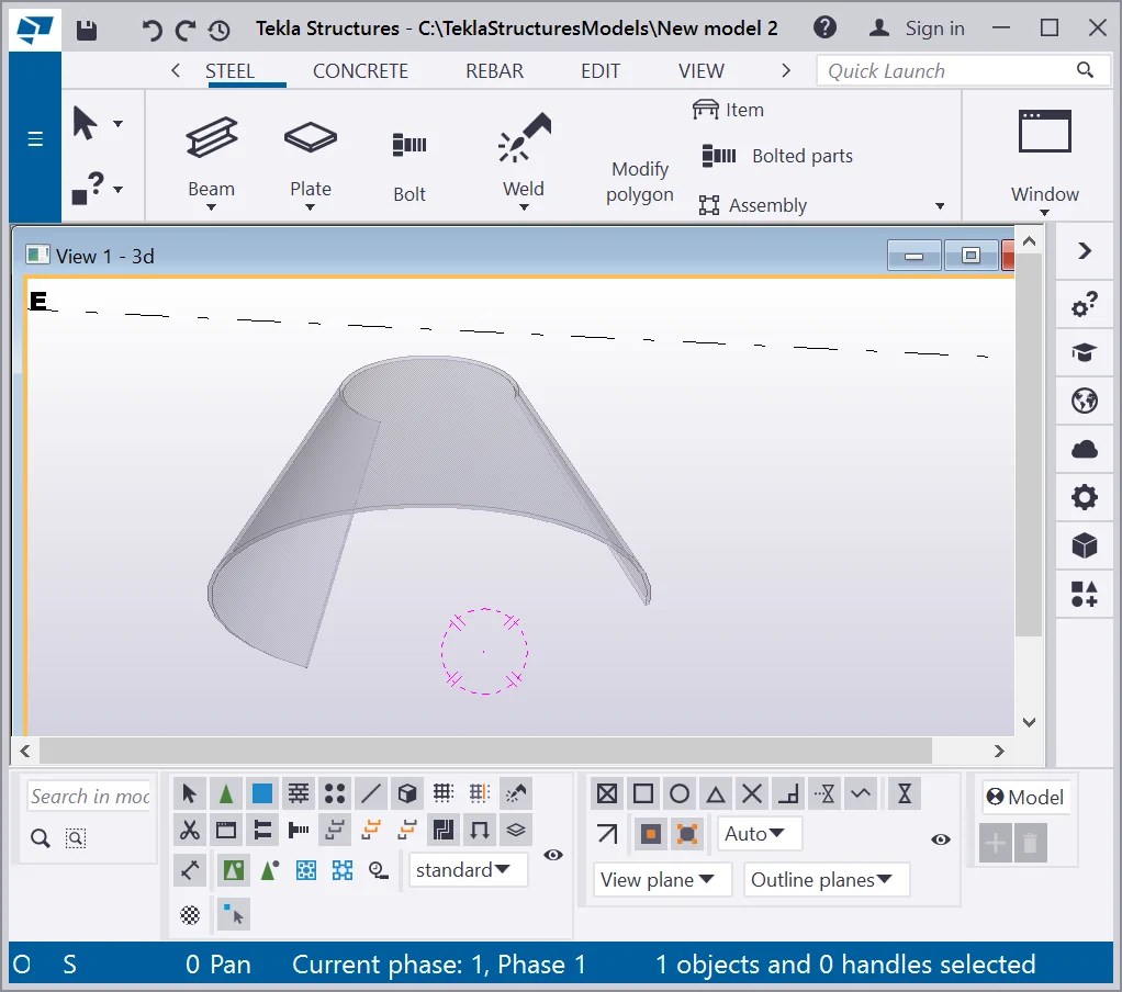
Press the mouse wheel button upon completion.
Present Tekla Structures version is not available on the “ Create stand-alone bent plate” tool

Rotate the view to see the object created.
Present Tekla Structures version is not available on the “ Create stand-alone bent plate” tool
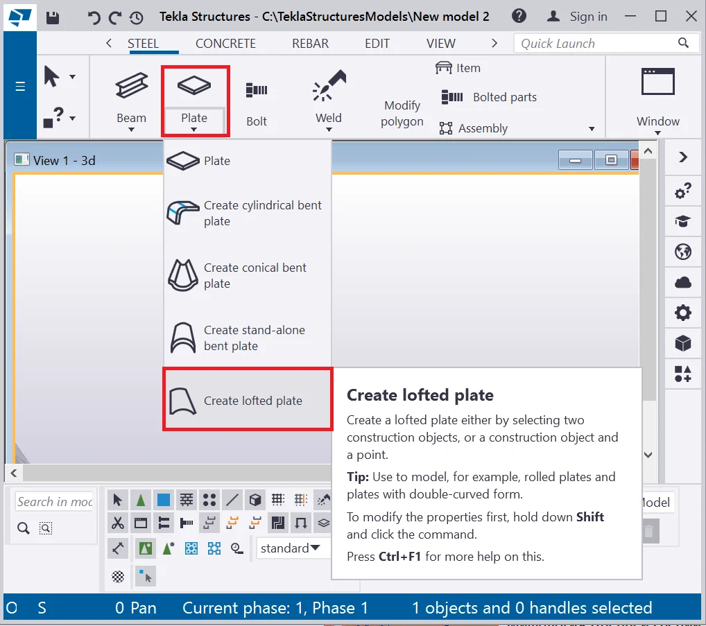
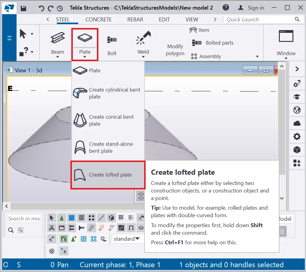
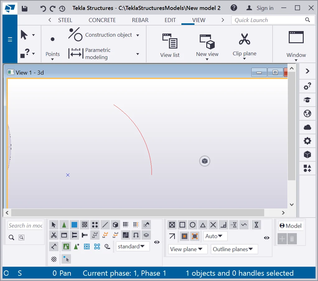
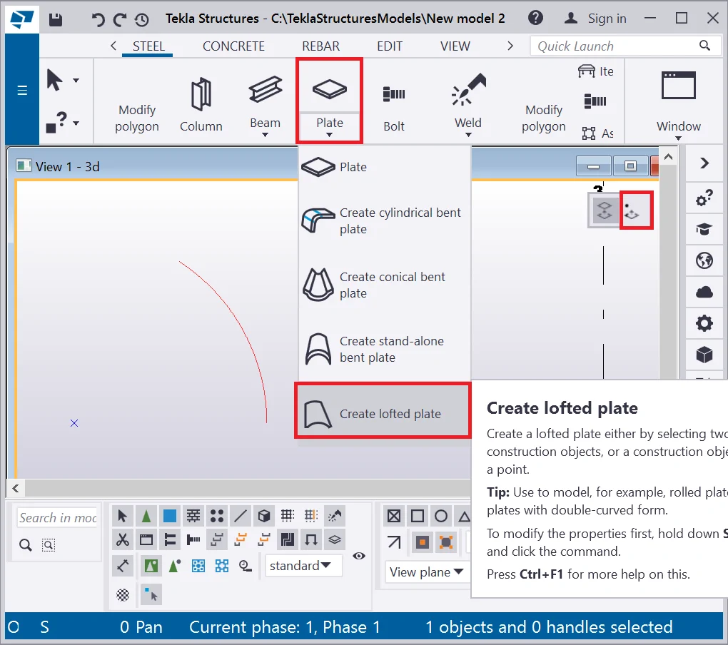
This tool allows creating a plate of a complex shape, not derivable from
Present Tekla Structures version is not available on the “ Create lofted plate” tool
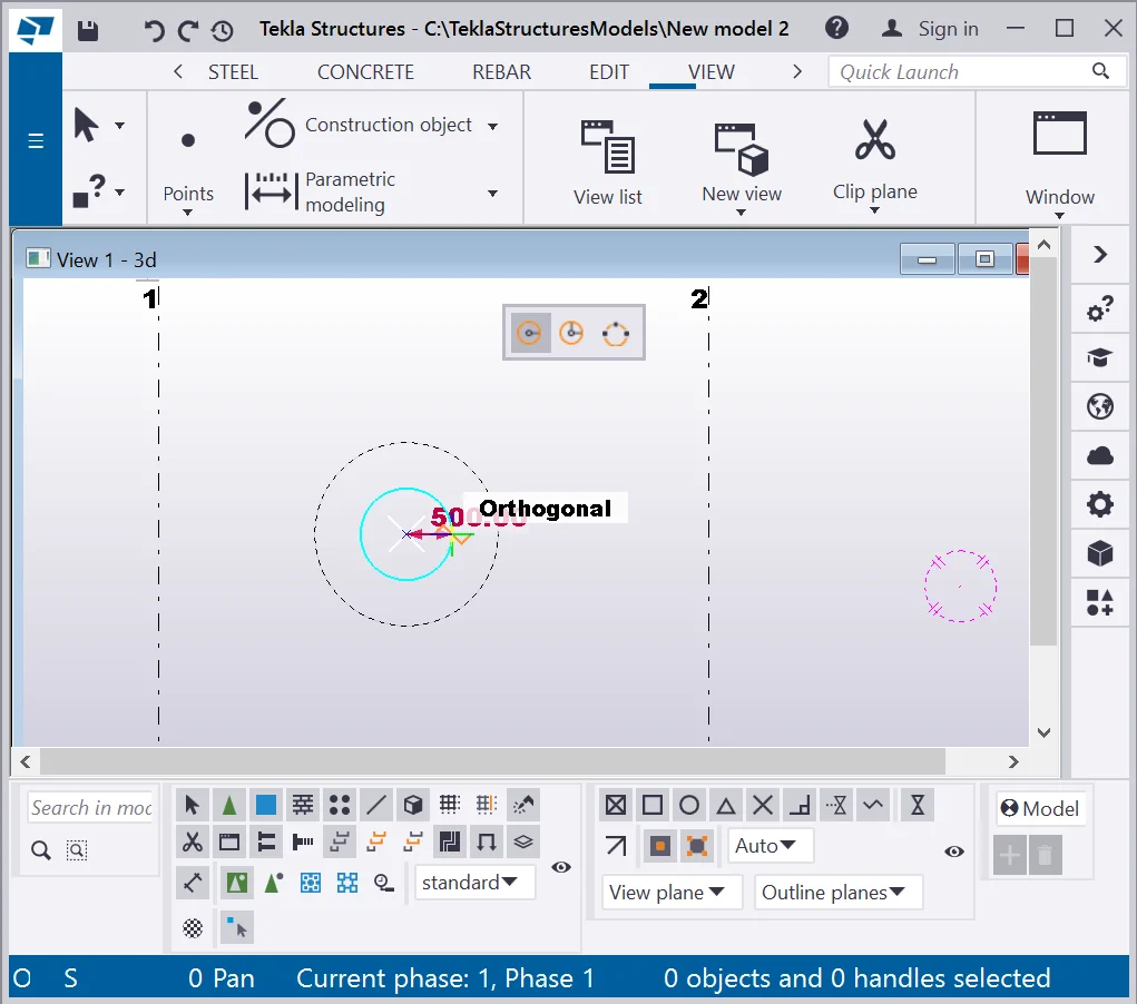
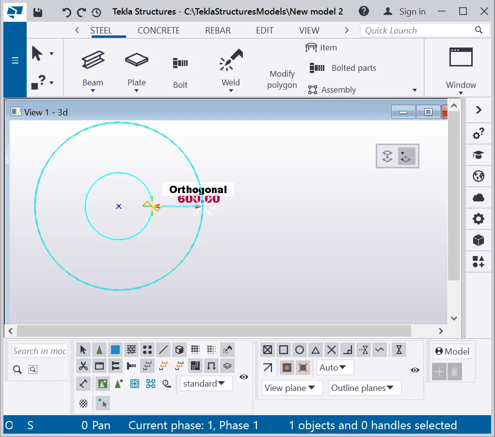
To examine the tool we will additionally use the construction geometry
Present Tekla Structures version is not available on the “ Create lofted plate” tool
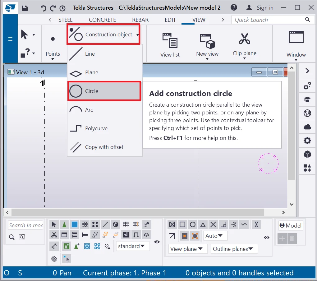
Create one more circle with a radius of 500mm.
Present Tekla Structures version is not available on the “ Create lofted plate” tool
Allocate the circles one above the other using the “Move Special” tool. Select the smallest circle and in the right-click menu select the “Move Special/Linear” tab. In the dialog box indicate the Z-axis value of 500mm and press the “Move” button.
Present Tekla Structures version is not available on the “ Create lofted plate” tool
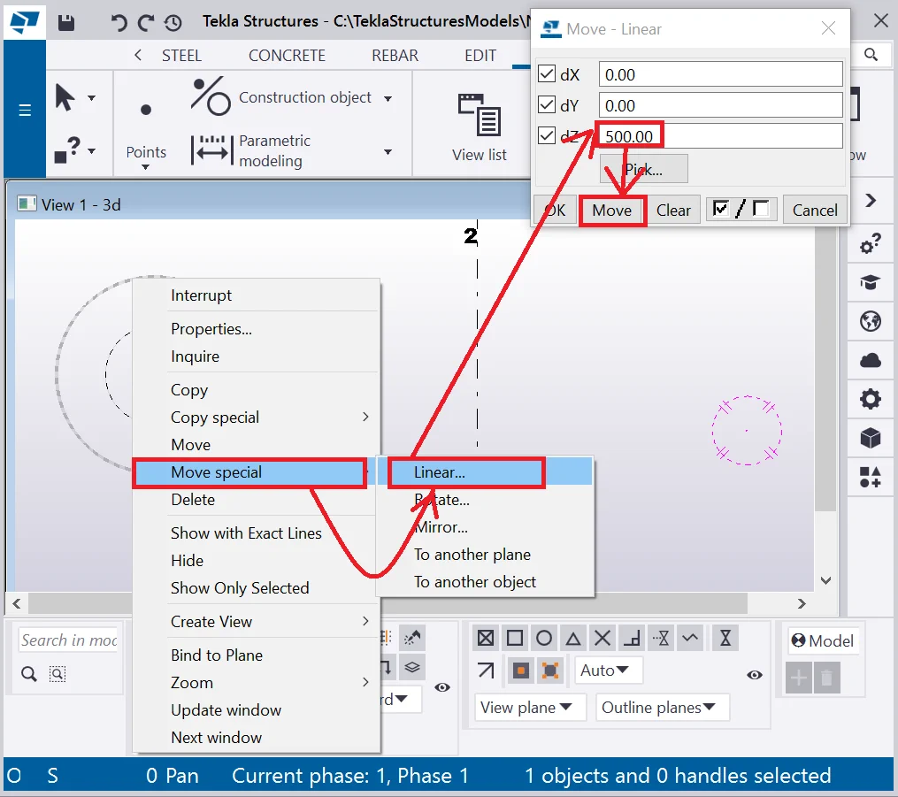
Thus one of the circles has moved 500mm upwards.
Present Tekla Structures version is not available on the “ Create lofted plate” tool

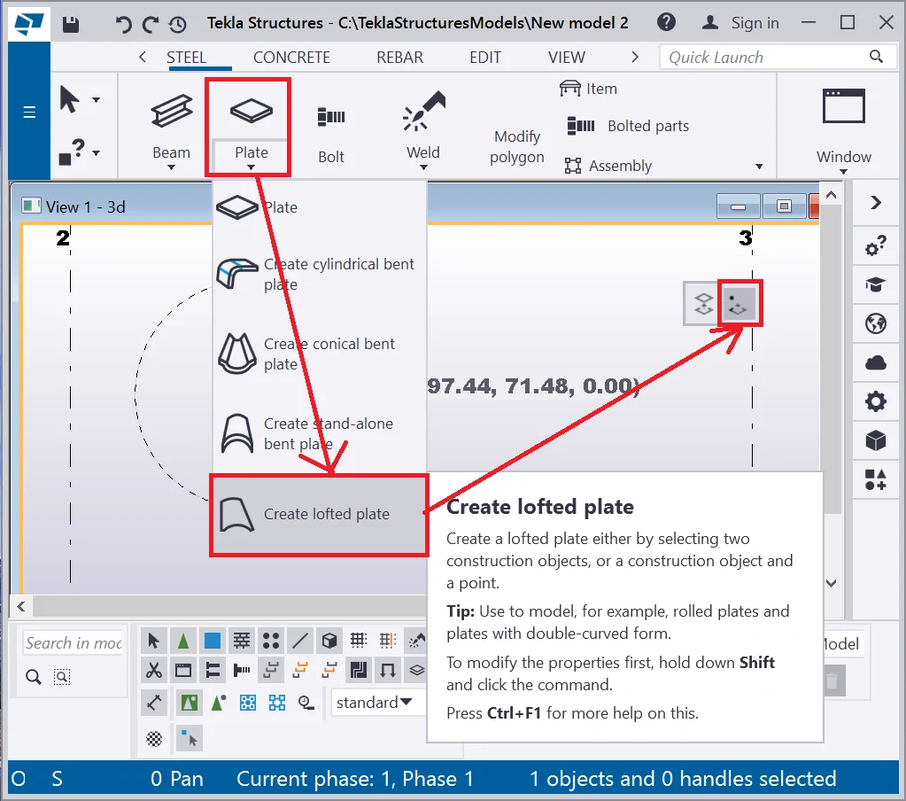
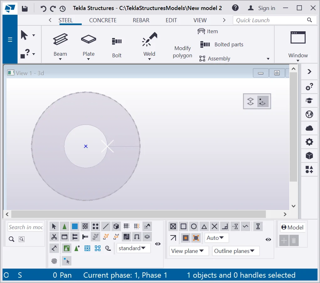
Go to the “Plate” drop-down menu and select the “Create lofted plate” tool, specify the “Create using two construction objects” options and click on the circles.
If you carried out the operations in a correct way, then you have got
Present Tekla Structures version is not available on the “ Create lofted plate” tool
Let’s examine creating a lofted plate by using the “1 construction
Present Tekla Structures version is not available on the “ Create lofted plate” tool

Select from the “Plate” drop down menu the “Create a lofted plate” tool and specify “Create using 1 construction object and point”.
Present Tekla Structures version is not available on the “ Create lofted plate” tool
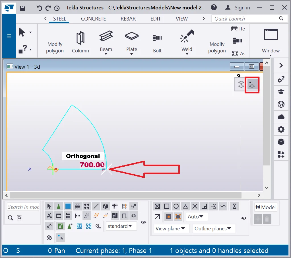
Indicate the second circle’s radius by pointing it using the mouse
cursor. Refer to the picture below:
Present Tekla Structures version is not available on the “ Create lofted plate” tool
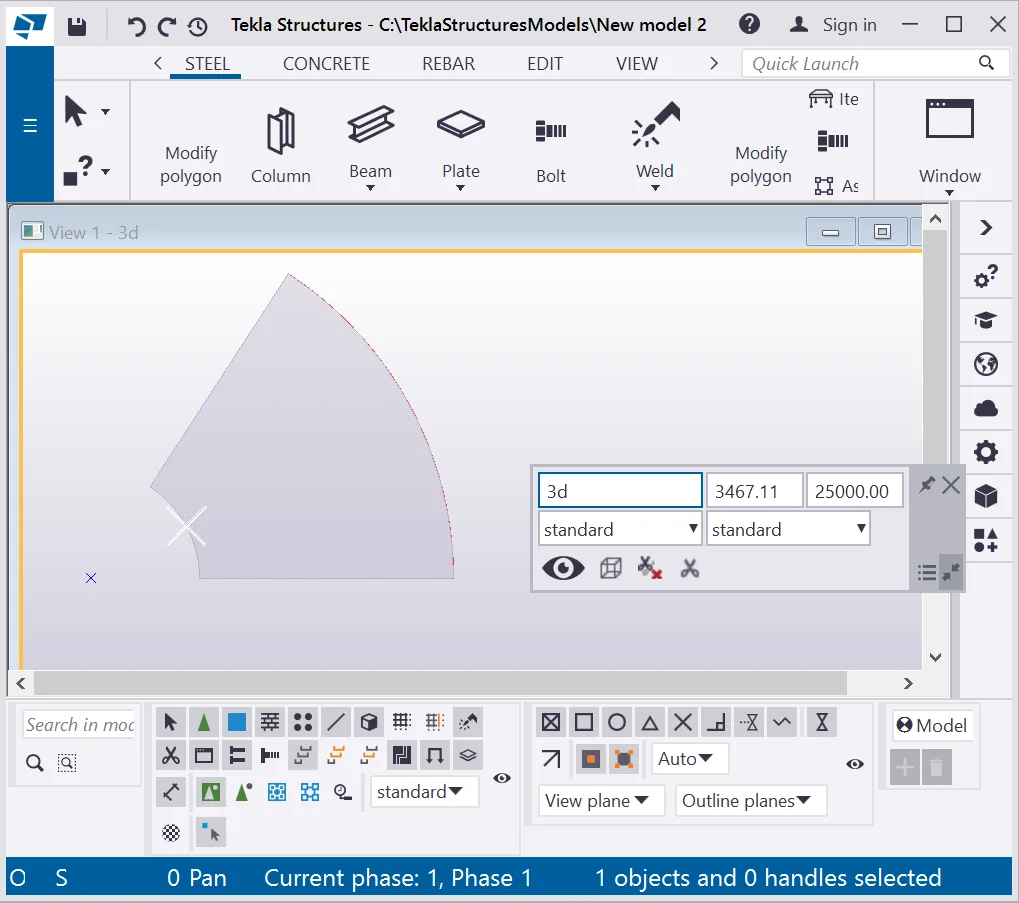
The following plate results of enabling the tool:
Present Tekla Structures version is not available on the “ Create lofted plate” tool
The “Create lofted plate” tool works with various construction
Present Tekla Structures version is not available on the “ Create lofted plate” tool

Indicate the arc circle center, and the arc circle radius of 1000mm at
Present Tekla Structures version is not available on the “ Create lofted plate” tool
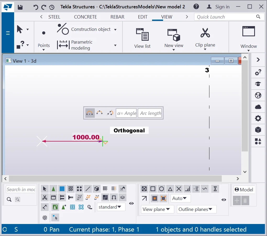
Specify the construction arc minute.
Present Tekla Structures version is not available on the “ Create lofted plate” tool
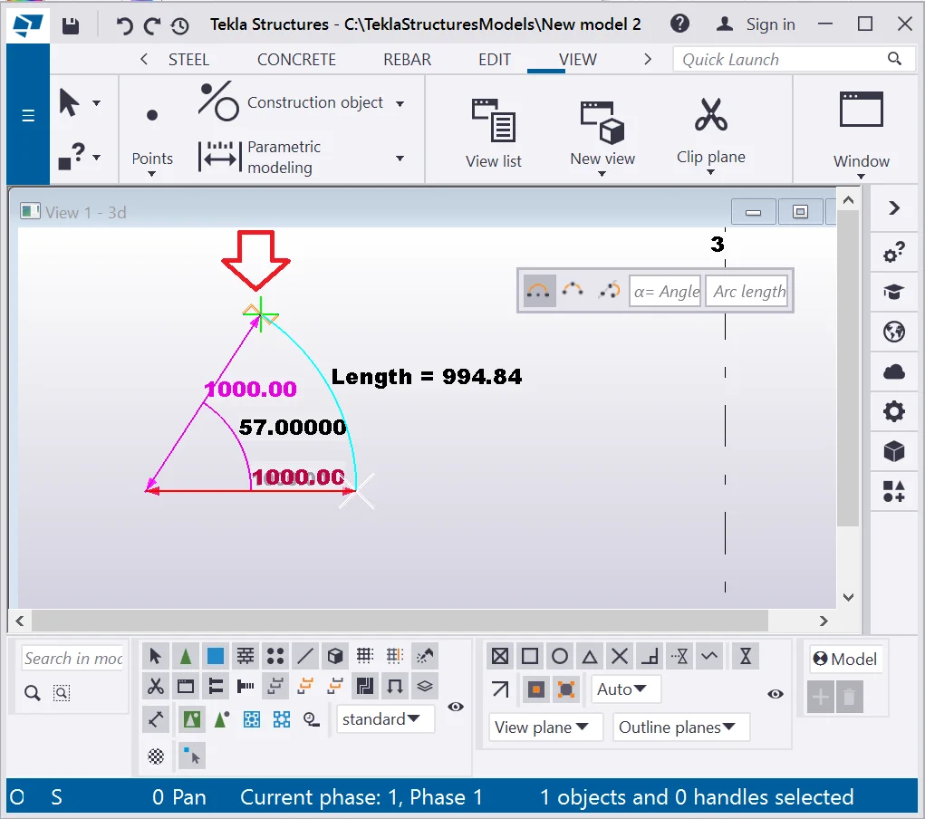
The following construction arc was created.
Present Tekla Structures version is not available on the “ Create lofted plate” tool
Enable the “ Create lofted plate” tool, of “Create using
Present Tekla Structures version is not available on the “ Create lofted plate” tool
Select the construction arc.
Present Tekla Structures version is not available on the “ Create lofted plate” tool
Indicate the second radius of the complex geometry object. Refer to the
Present Tekla Structures version is not available on the “ Create lofted plate” tool
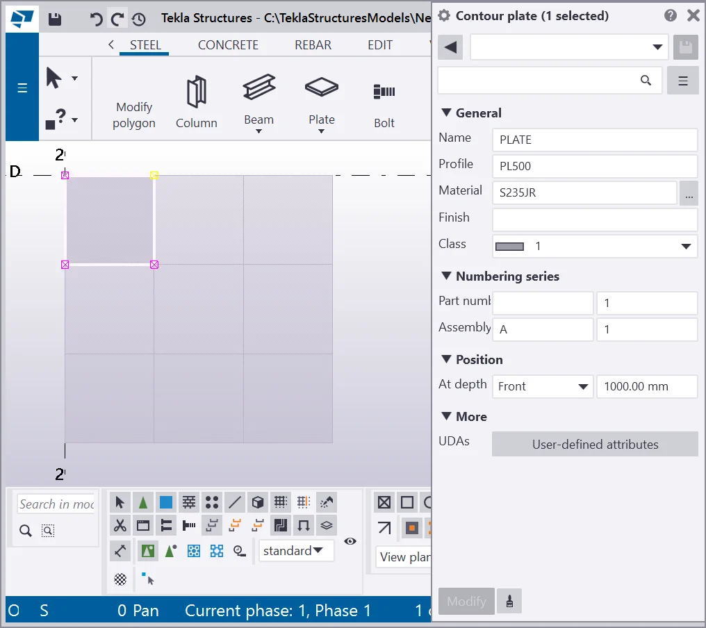
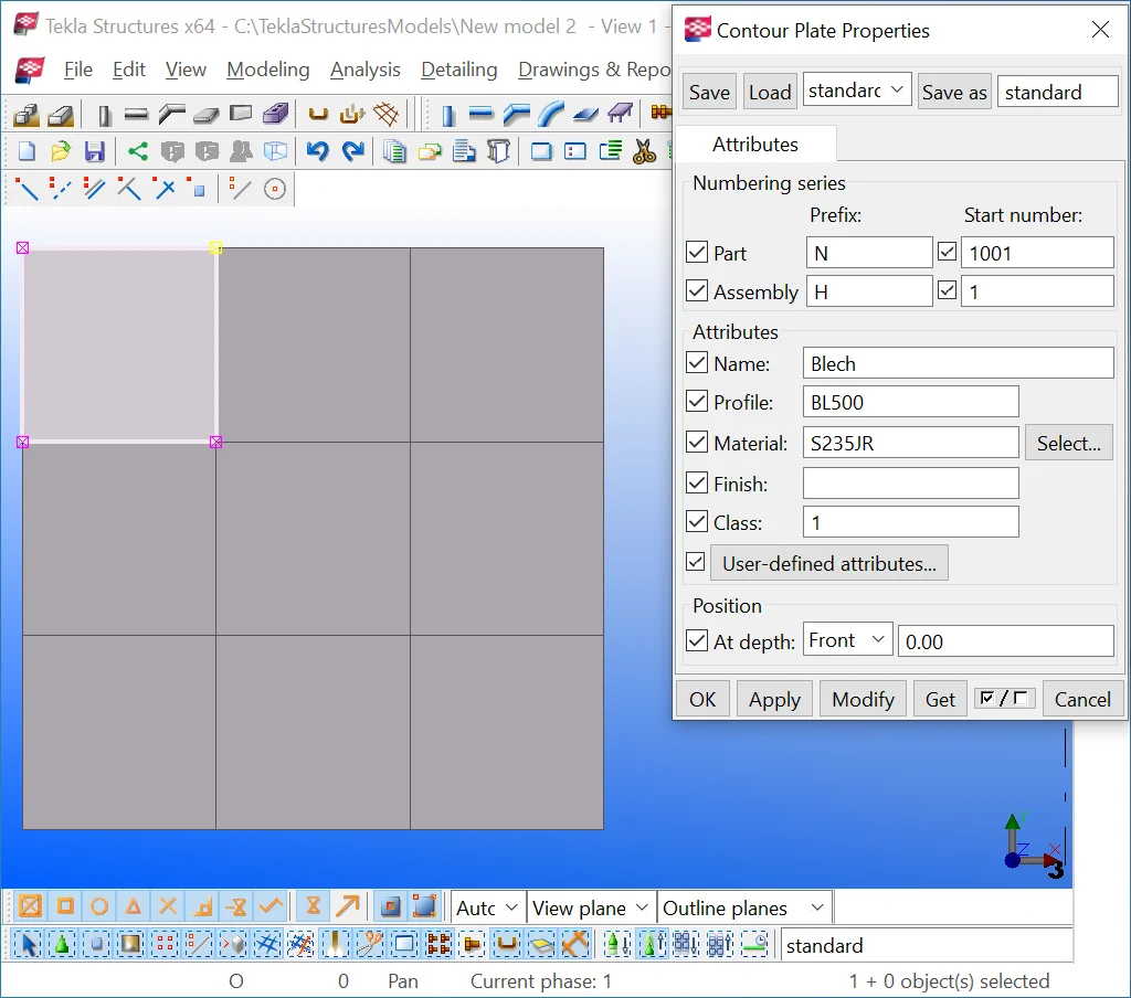
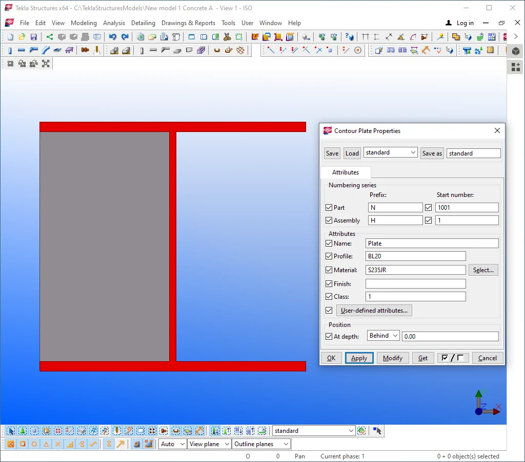
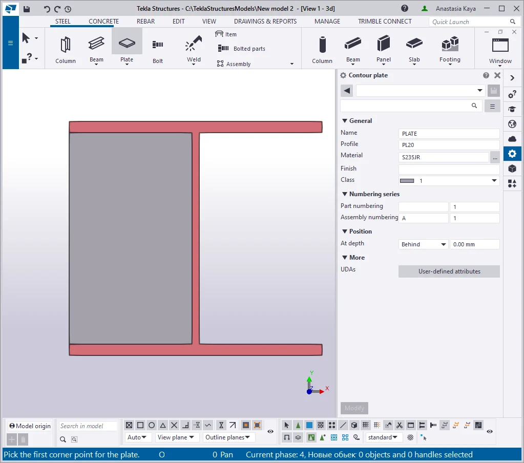
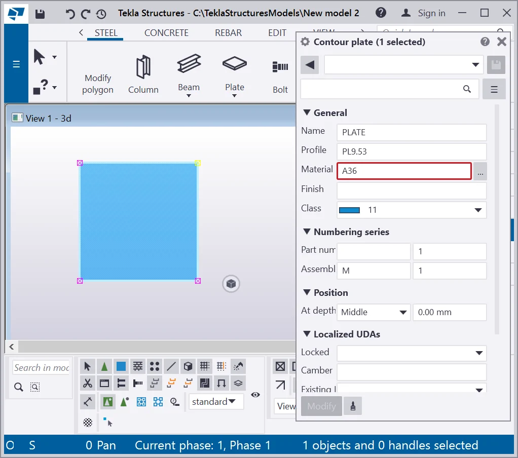
Go to the contour plate properties menu.
The majority of its fields are similar to the column object (see below).

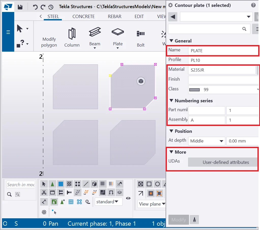
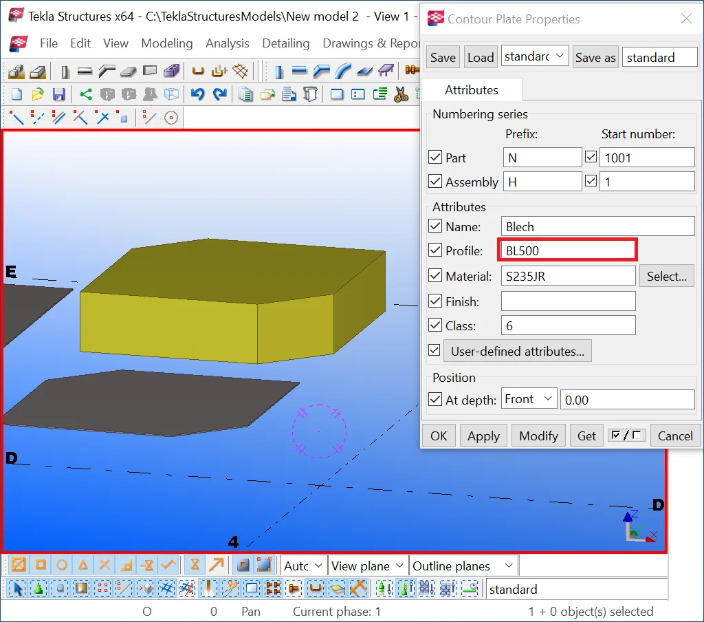
The “Profile” field defines the steel sheet title to be reflected in the bill of materials and title numeric part stands for the steel sheet width parameter value.
Note that a profile title is composed of its width value and a symbol/ symbols combination forefront it. Missing out the symbol does not affect the contour plate representation, but it is considered an error on the reason that the bill of materials will be defined by just a number at the respective profile field.
Different countries have their own steel sheets marking. The most
frequently used nomenclatures for the steel sheets profiles are as shown
below:
|
Eng |
|
|
PL10 |
BPL10 |
|
PL-short form of “plate” Note there is no space between textual and numeric symbols |
|
Rotate the view in the way to see the plate from its width perspective.
Select a plate and set its profile width value to - 500 (do not edit any
Also, modify its “Class” type to assure a better representation

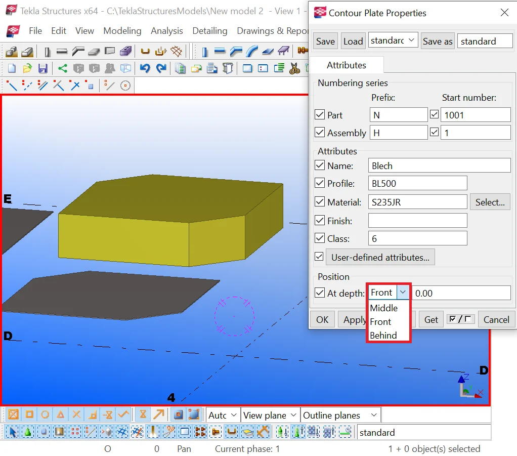
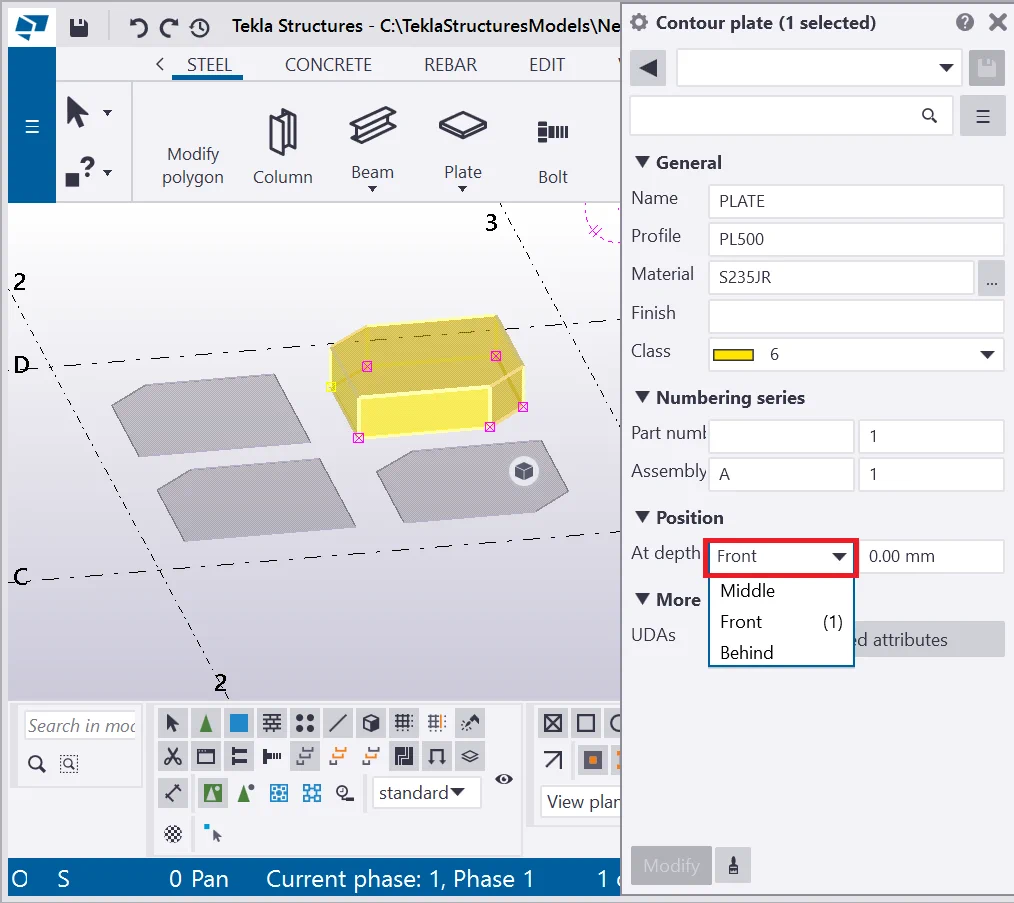
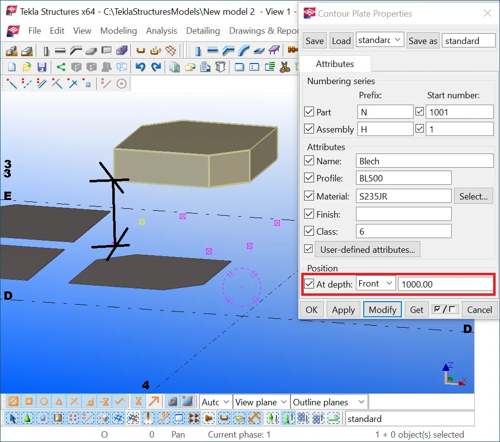
The “Position” field brings in/out the contour plate into 3 (three) different positions as respects to the points created.
|
Front |
Middle |
Behind |
|
|
|
|
Exercise switching the contour plate positions to Middle, Front, Behind.
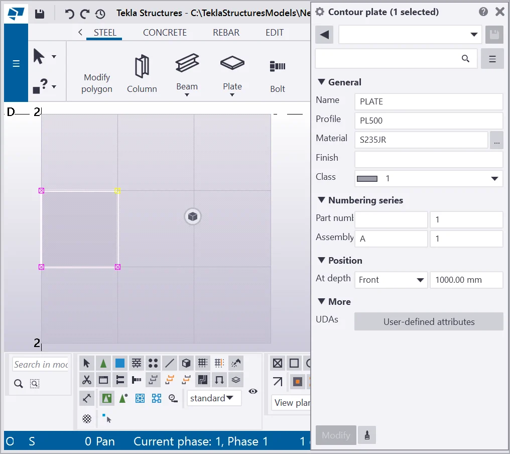
The “Depth offset” box correspondent to the “Position” field specifies the offset value of the plate as regard to the plane defined by the initial points.
This parameter is not of frequent use. Let’s edit its value to 1000 and subsequently to -1000 and examine the results. Do not use this field to displace a plate.

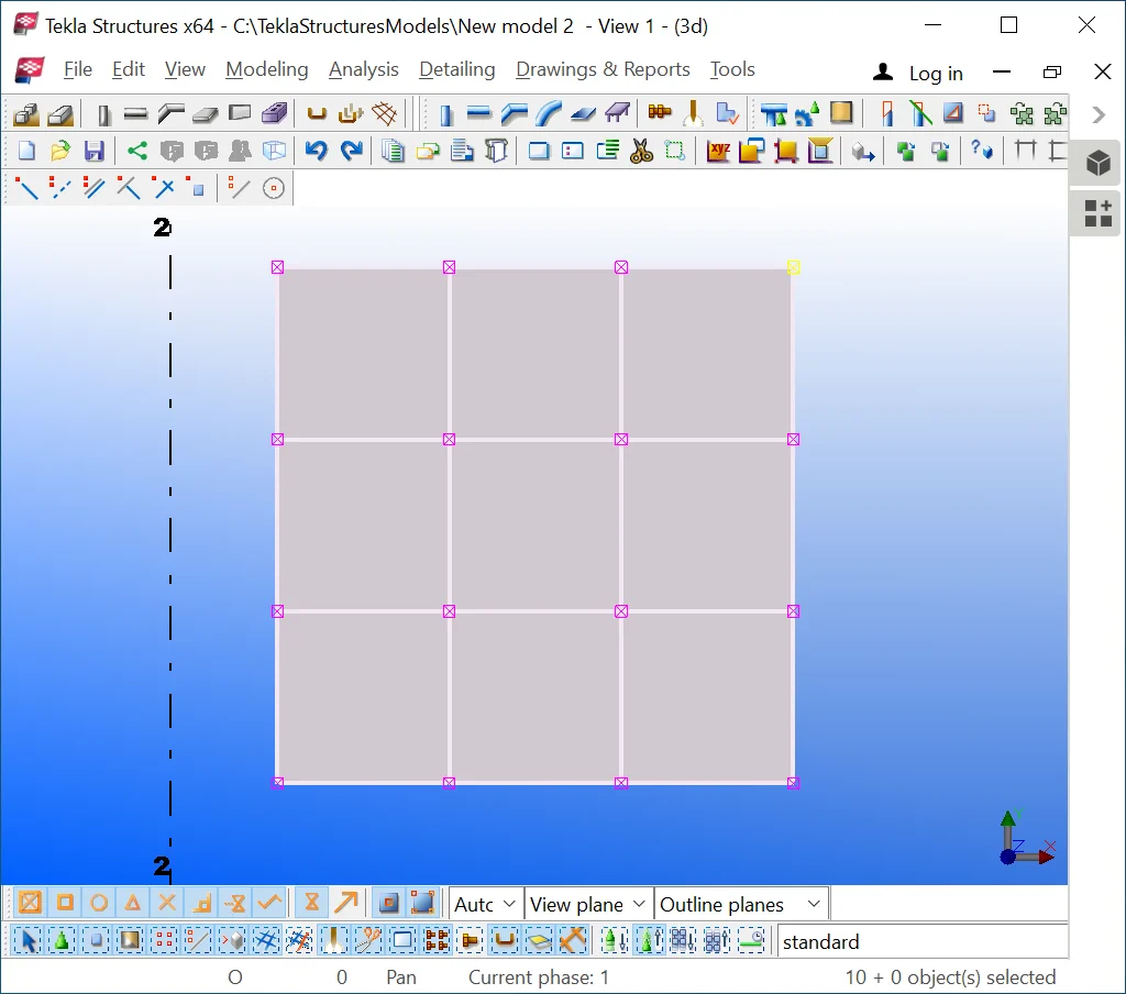
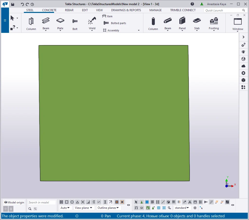
Delete the objects and create a new plate with dimensions of 1000 x 1000mm
Using the Ctrl+C key combination, execute copying the contour plate

Selecting a point from the contour plate surface allows editing the geometry
To select a point, make sure that the “Direct modification”
tool is switched off.
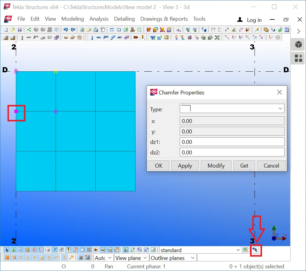
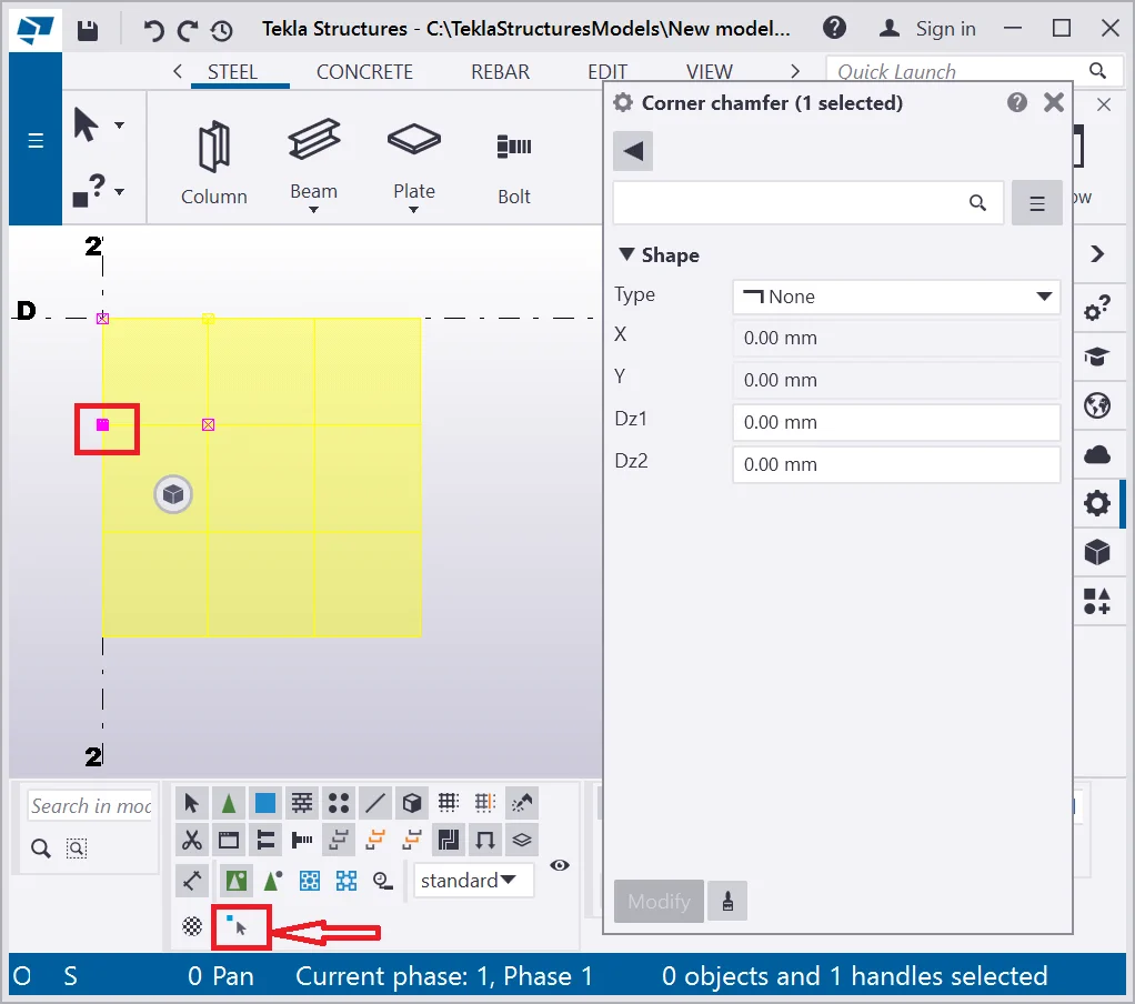
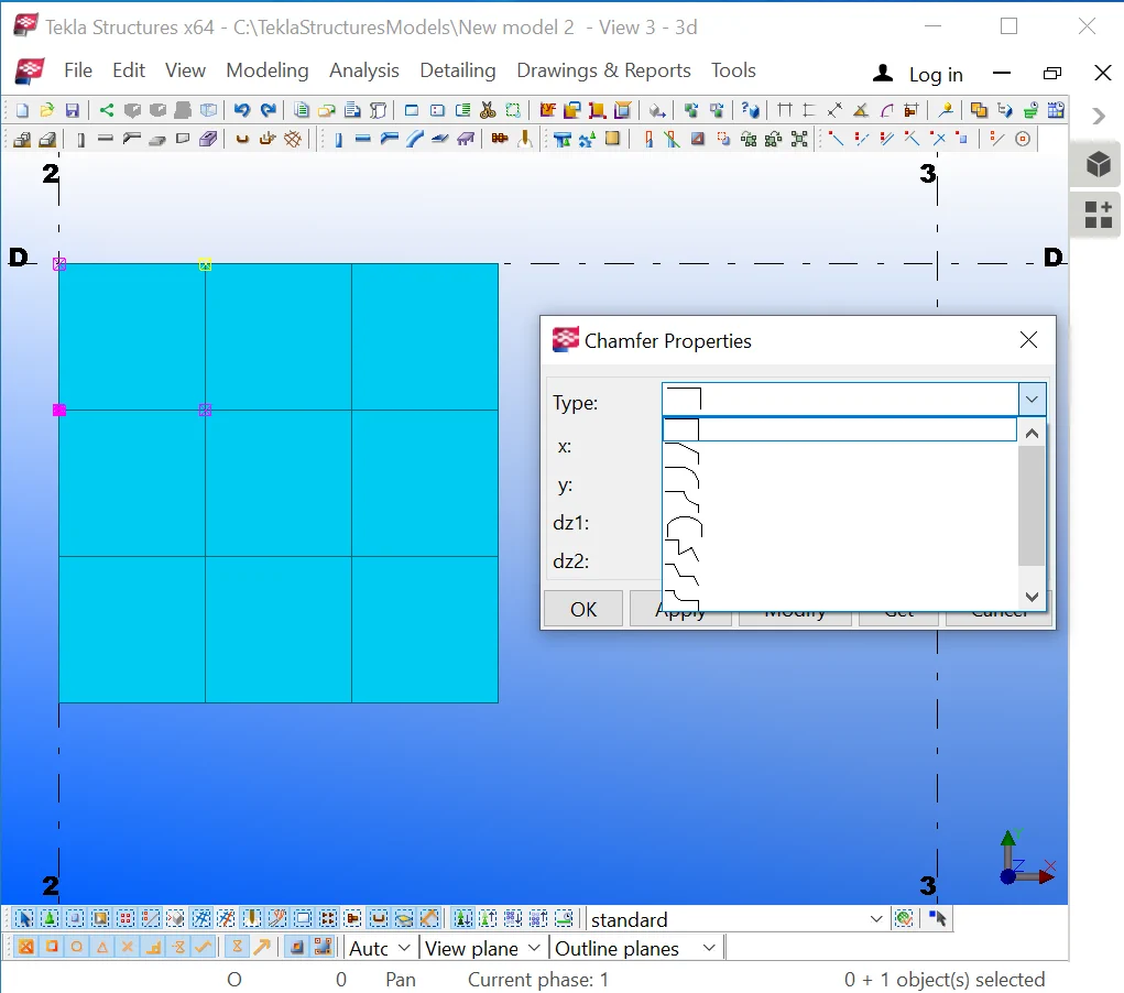
The “Chamfer” tool allows editing the contour plate geometry
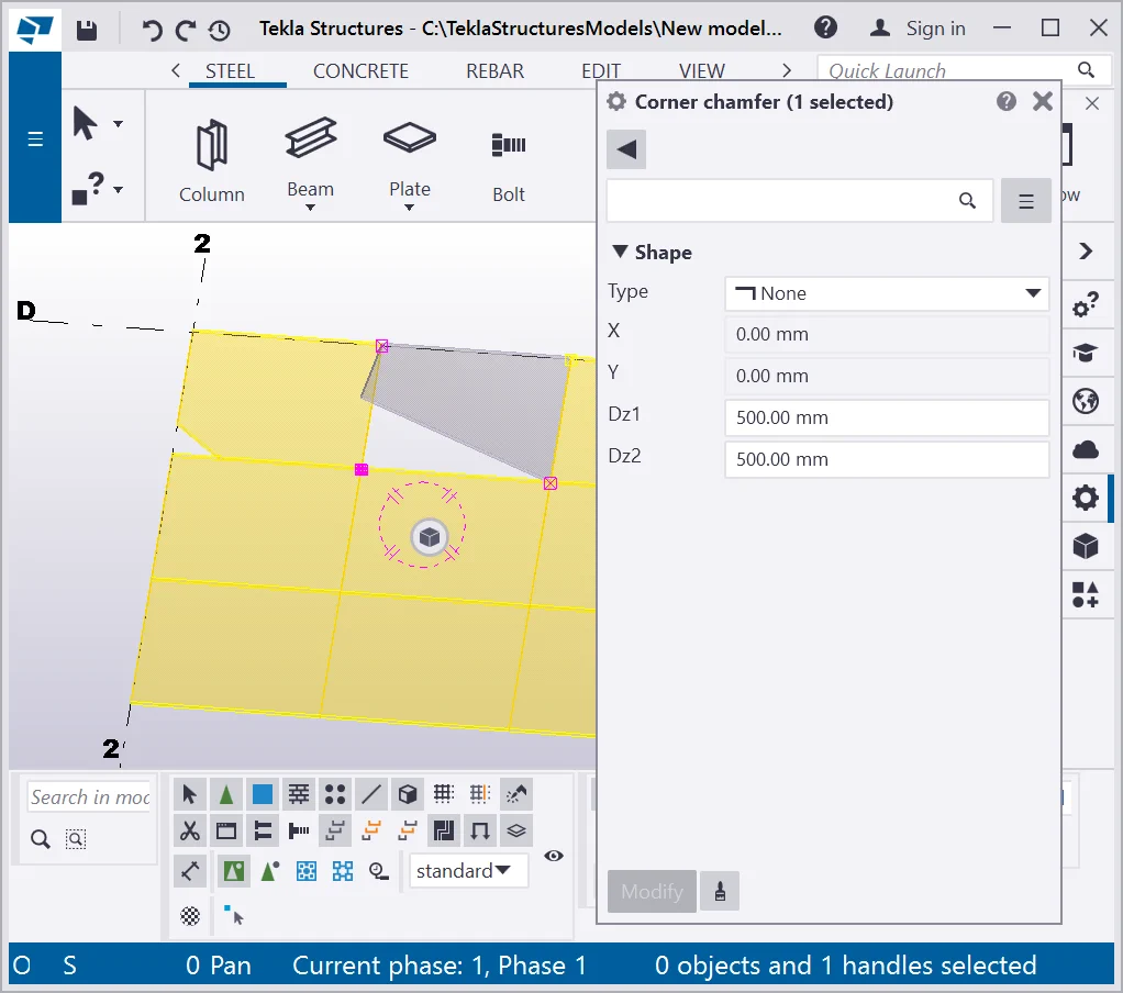
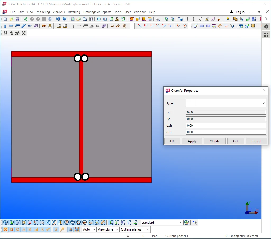
Making a double-click at a plate point opens the “Chamfer Properties” dialog window, where at the “Type” field, there are many chamfer options available. By default, chamfers are set at the “None” type, with the other fields, such as X, Y, Dz1, Dz2 deactivated.

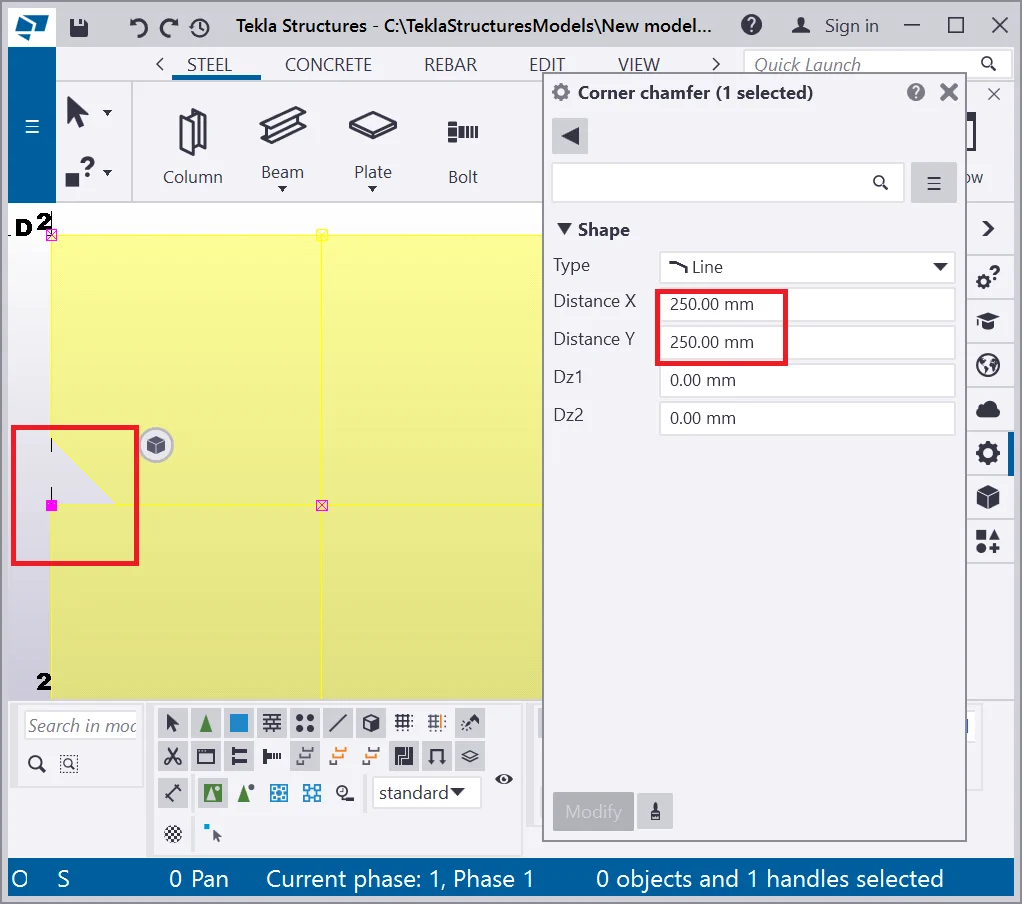
Let’s set the chamfer type to the “ Line” (hollow chamfer)
option.
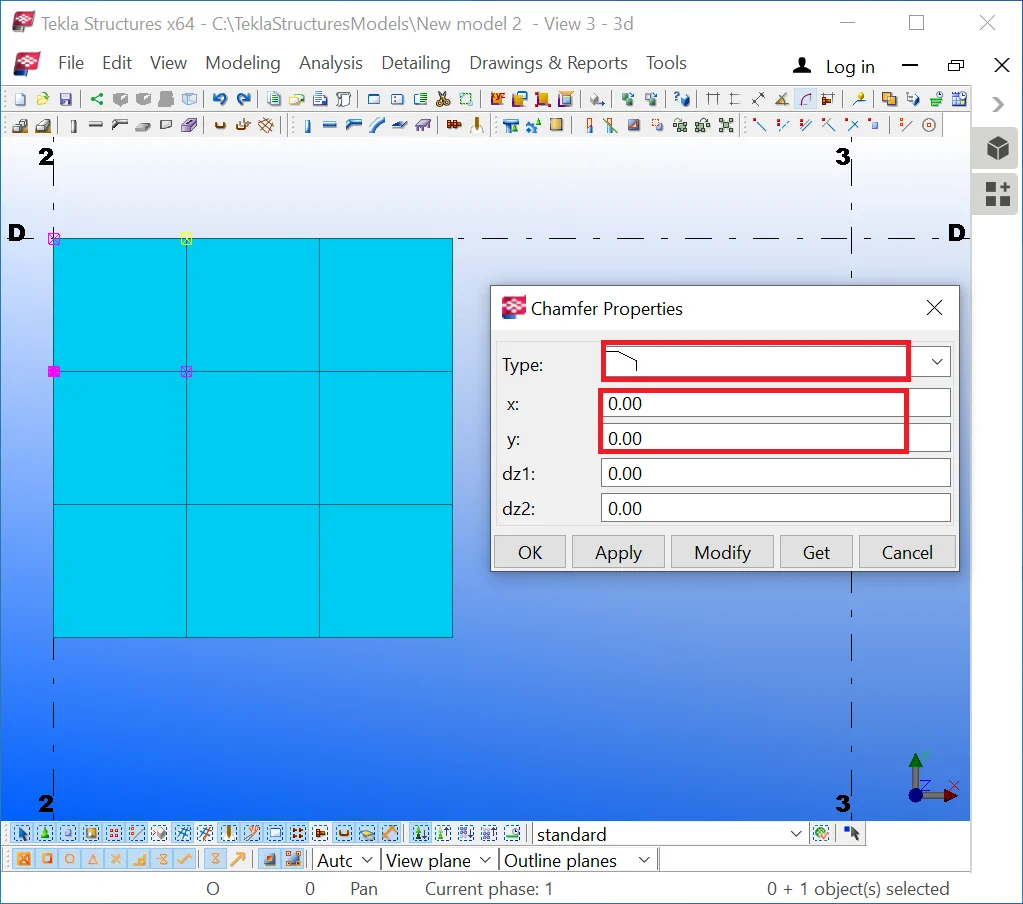
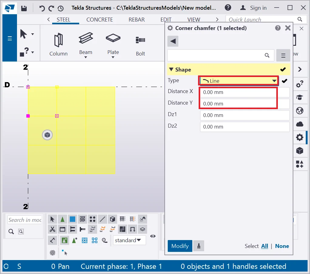
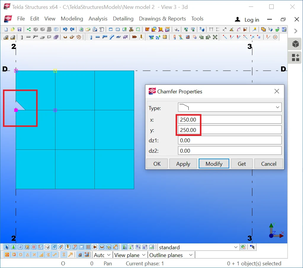
Updating the chamfer type activates the “X”, “Y” fields. Please specify into these fields the value of 250 mm. Compare your results to the below:
Exercise applying various chamfer types for other points as well.
The “Dz1” and “Dz2” fields change the width value of a plate in a point. It is a rarely used tool, as manufacturing a metal sheet of this type requires executing forge works, rarely used in construction.
Though this tool is frequently used for grounding modeling as it allows
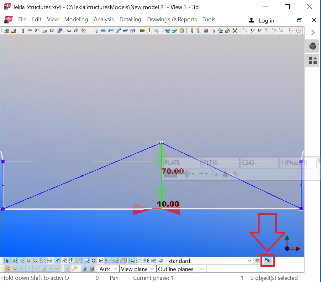
Let’s select any arbitrary point and edit its Dz1 field value to 500 mm.
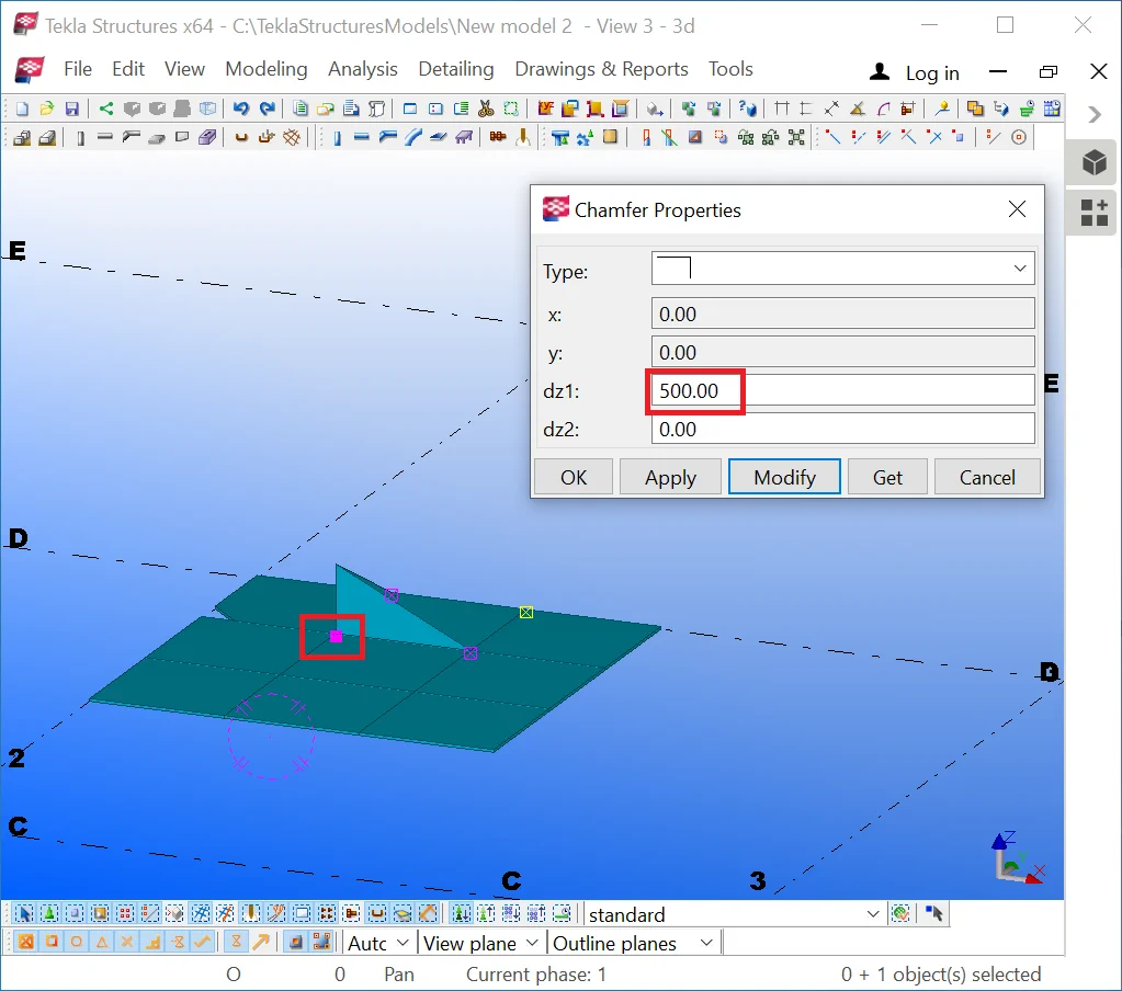
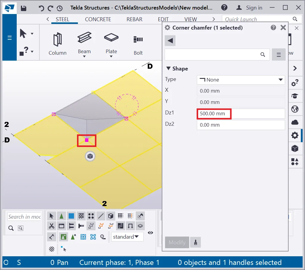
Rotate the view and examine the result: the contour plate width became
Edit the Dz2 value to 500mm and examine the object created. It is a curved plate of a constant thickness.

Exercise editing the above field values and examine their function. Note
Bring the model to the initial position as it is shown below.
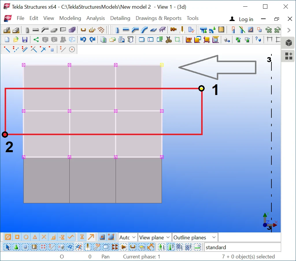
It is important to mention that selecting points at a contour plate is not the same as selecting the contour plate as an object. To select several points hold on the “Shift” key pressed and subsequently click on the points using the mouse cursor. This method is applicable for a small number of points. For a large number of points proceed on selecting by framing. It is really important to consider the direction of selecting the objects by frame in TS, thus creating a frame from right-to-left and left-to-right directions brings different outputs.
The right-to-left framing direction allows selecting an object entirely.
Thus, partial selection of an object ( or its points) is available by
The algorithm for selecting a large number of points by framing is as
Let’s move the points selected to 500mm downwards by using the “Ctrl+M”
(Move) hotkey combination.
Compare your results to those presented below:

Now let’s move the points selected at 1000 mm upwards.


Now, realign the points to the right at 500mm.


To remove the selection, click at any blank point of the view.
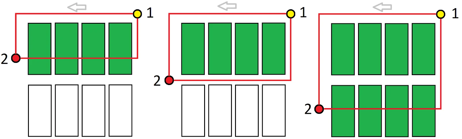
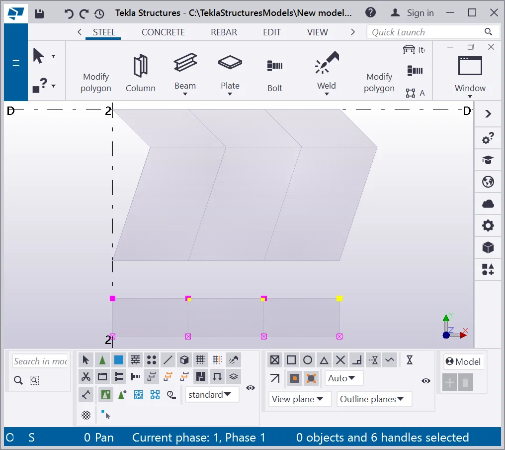
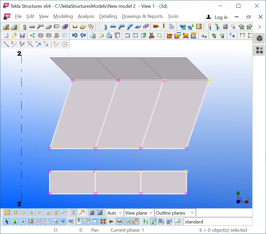
Now, select the top points of the plates as presented below. First of all select the objects where the points are located, thus we will highlight only the points of the bottom squares, without picking superposed ones.

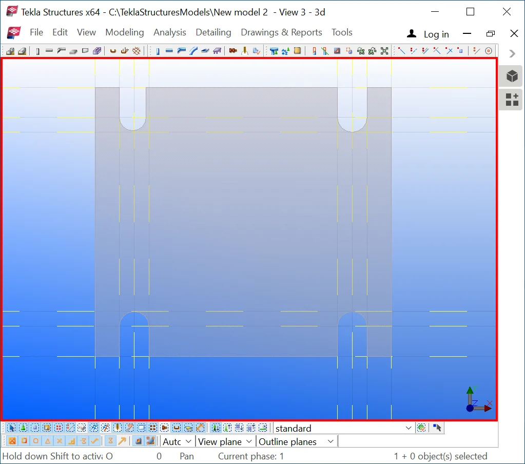
Move the points at 500mm downwards.
As a result, only the bottom plate squares got displaced.
If you fail on getting the same result as it is shown in the picture

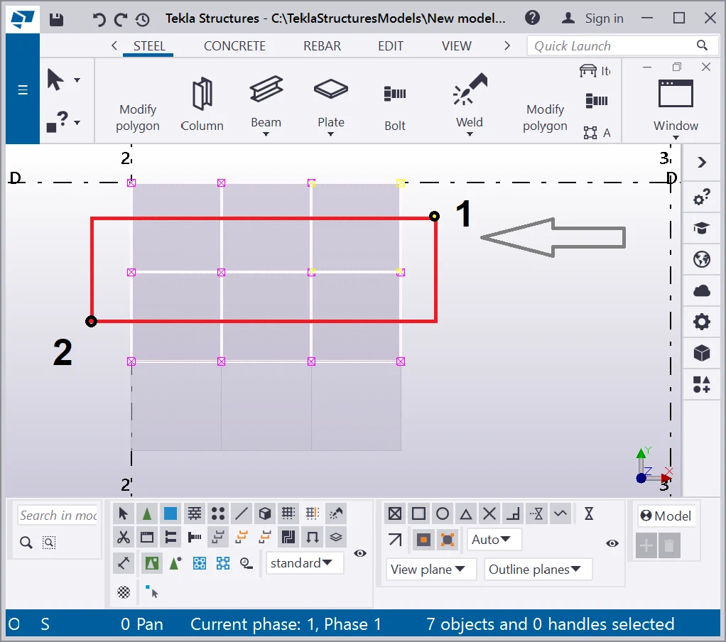
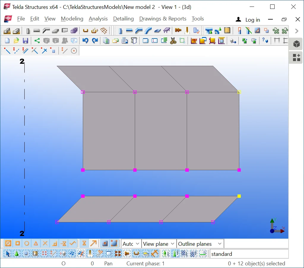
Now, select the objects as it is shown below.

Select the points at the objects as it is shown below, by using the left-to-right
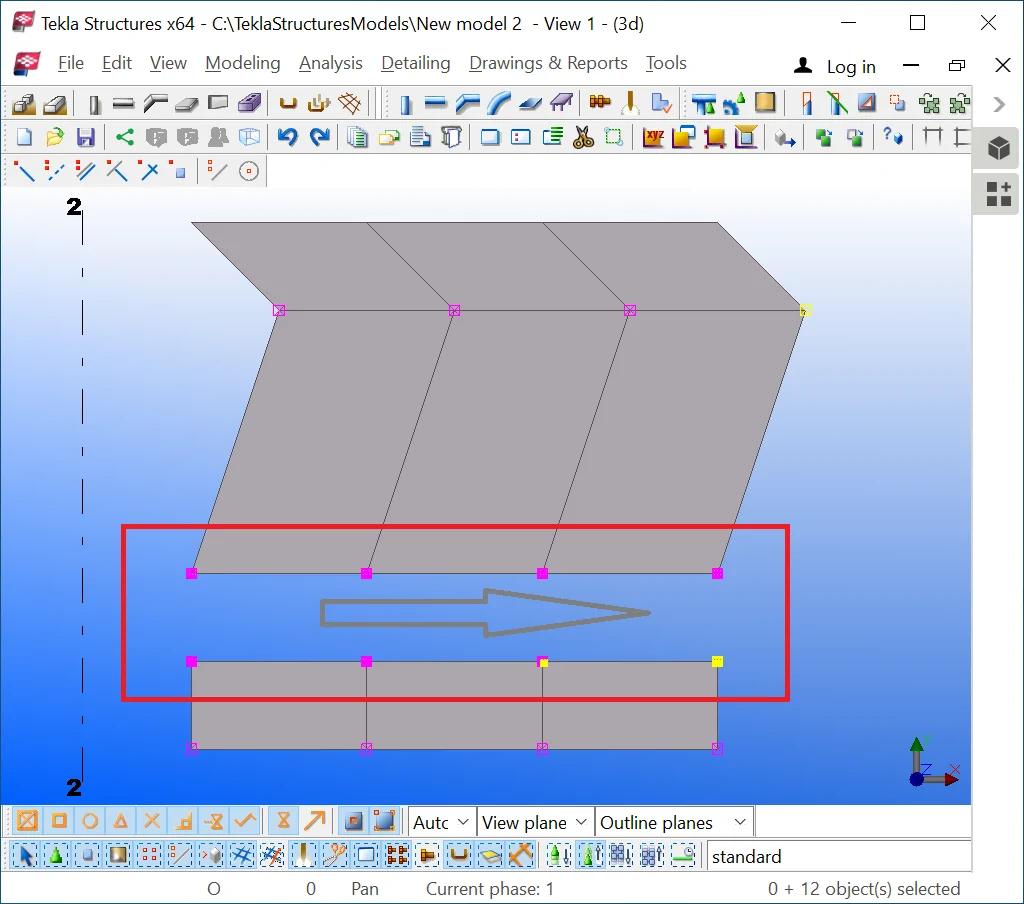

Move the points at 500mm to the right.
Selecting a large number of points is a very needful and frequently used
Try exercising by yourself selecting various groups of points and displacing them. Note that copying or deleting points by using this method is not appropriate.
Upon exercise completion, delete all contour plates and create new ones.
Simultaneously setting up the properties for several chamfers.
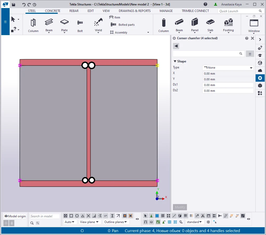
Select all the points of the plates in the following sequence: select the objects, press and hold on the “Alt” key and select the points. Pay attention to the selection scheme direction.
Simultaneously setting up the properties for several chamfers is done in the "Chamfer Properties" menu by editing values of parameters in the respective fields. However, if you try opening the "Chamfer Properties" menu by double-clicking at a point, other points' highlights will get removed. Exercise the above and see yourself.
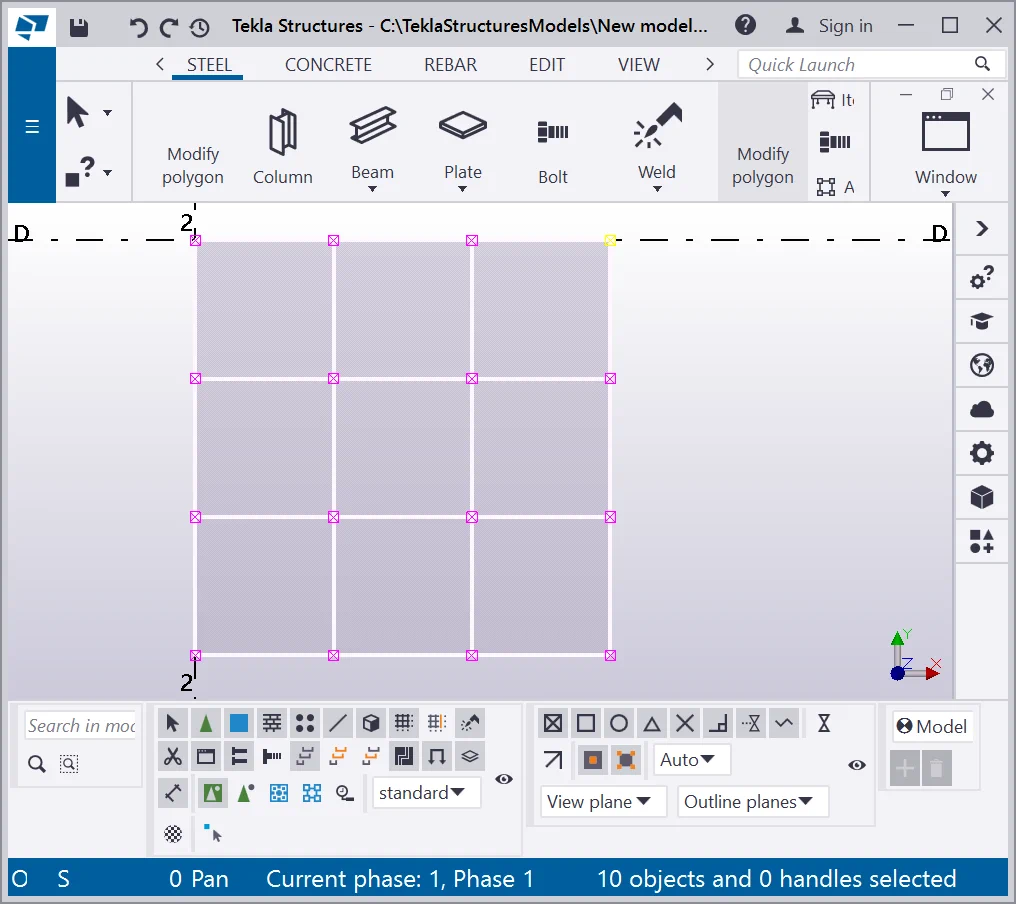
So as to not remove the highlights of the points, press and hold on the “Shift” key prior to accessing the "Chamfer Properties" menu.
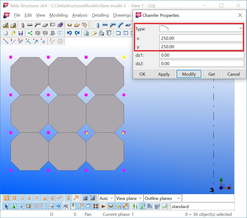
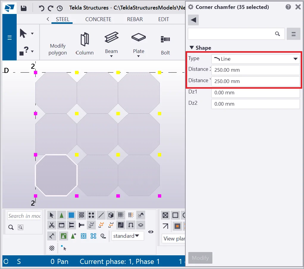
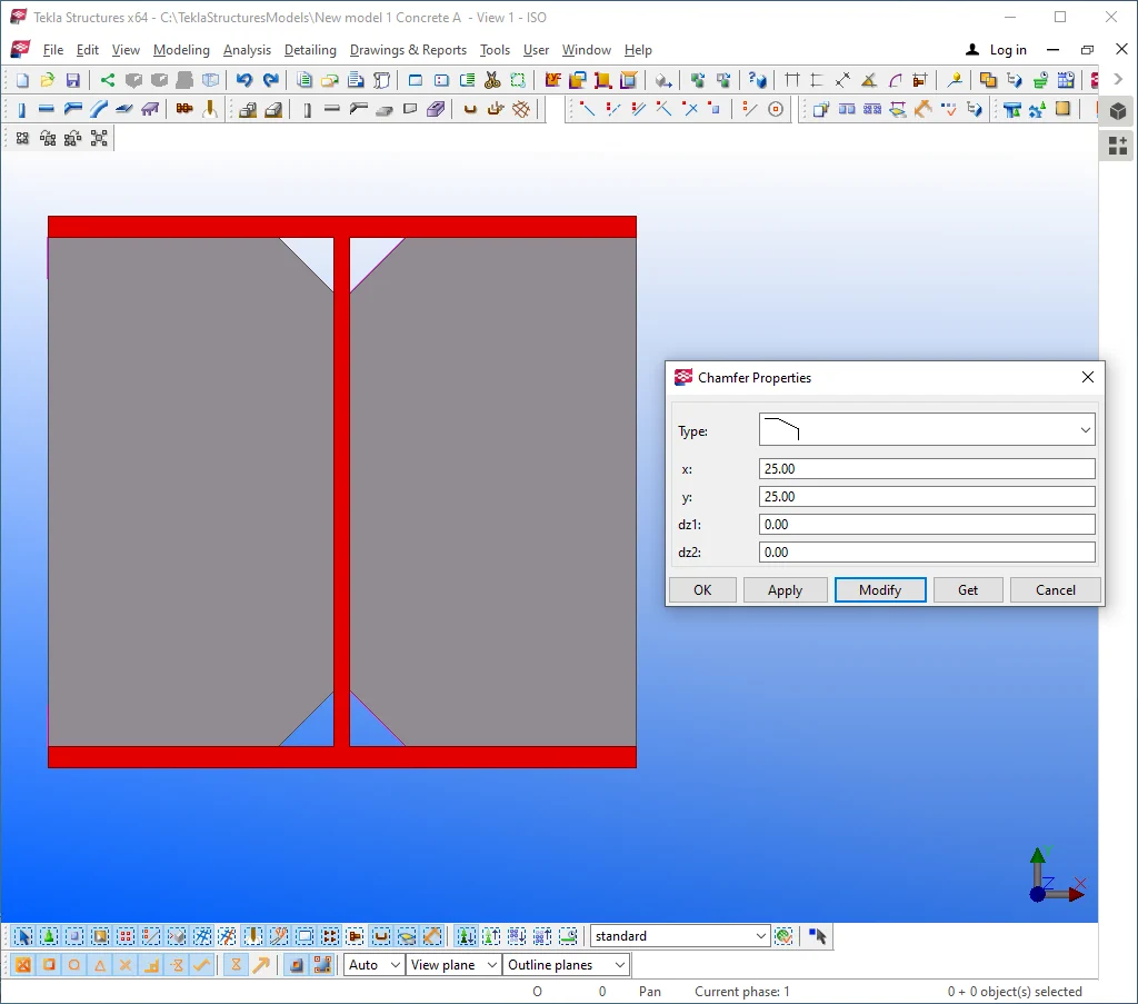
Change the Chamfer Type value to the “Line” (hollow chamfer), and the “X” and “Y” values to 250 mm. Compare your results to the below:
Let’s examine the chamfer type value “Arc with point” which rounds off chamfers, this being the very right method for drawing up a contour steel plate of a circle shape.
Let’s exercise by applying this chamfer type. Note that the
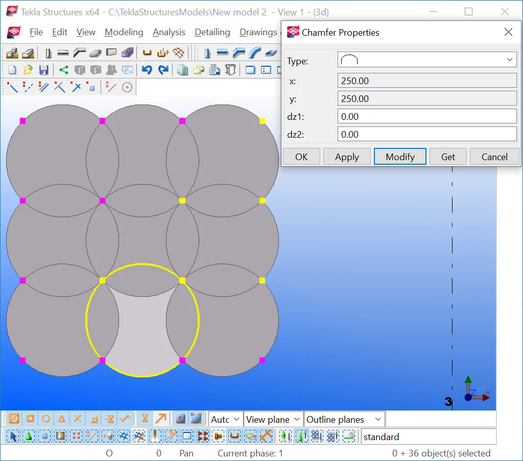
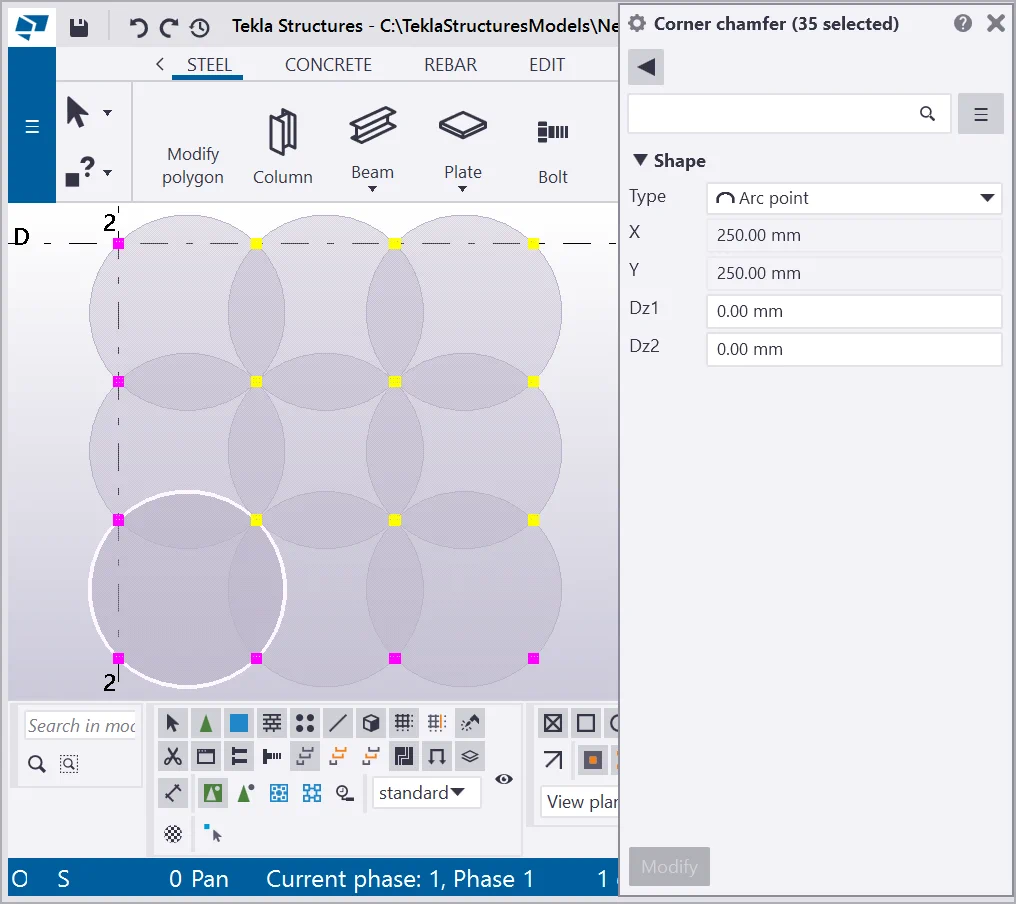
Navigate the Chamfer Type field menu and try out all the options available.
Creating a reinforcing plate
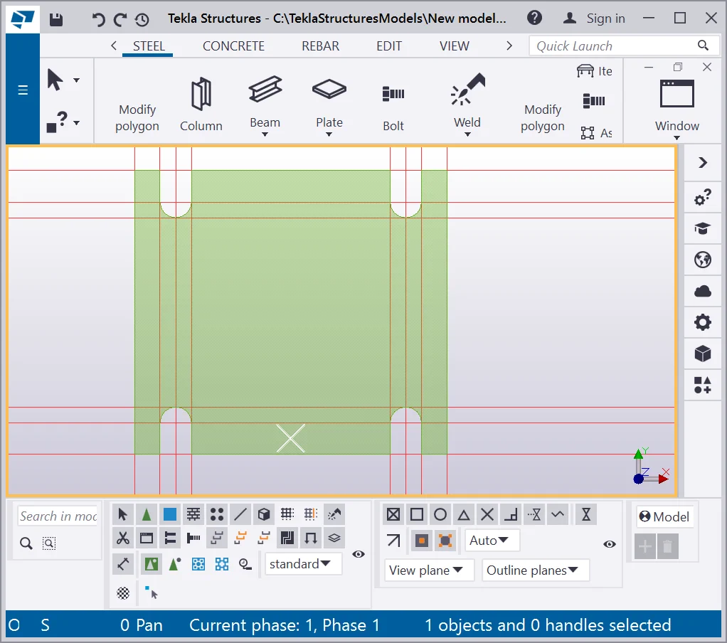
Go to the plane view and create a contour plate as it is shown below.
Make sure that “Snap to geometry lines/ points” tool is switched
on (v2021
 ,v21.1
 )
, allowing snapping construction objects to the profile's geometry.
)
, allowing snapping construction objects to the profile's geometry.
Copy the contour plate by using the Ctrl+C hotkey combination.
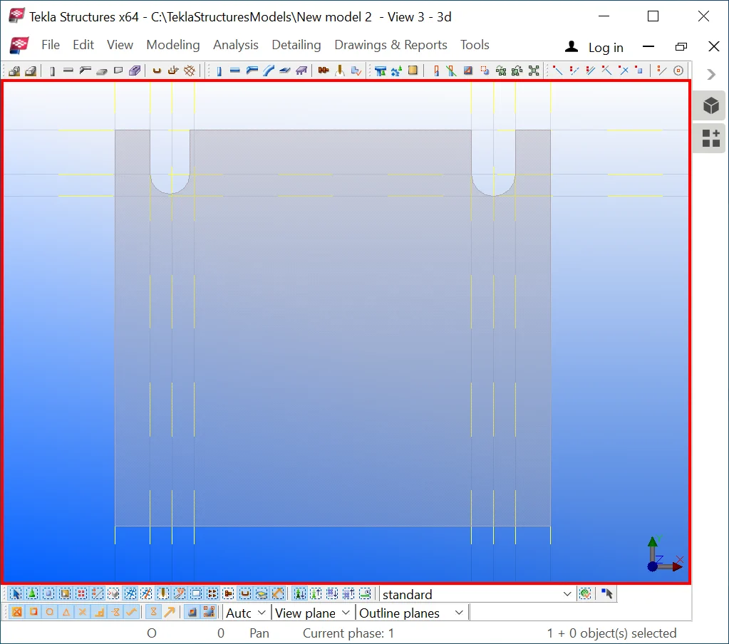
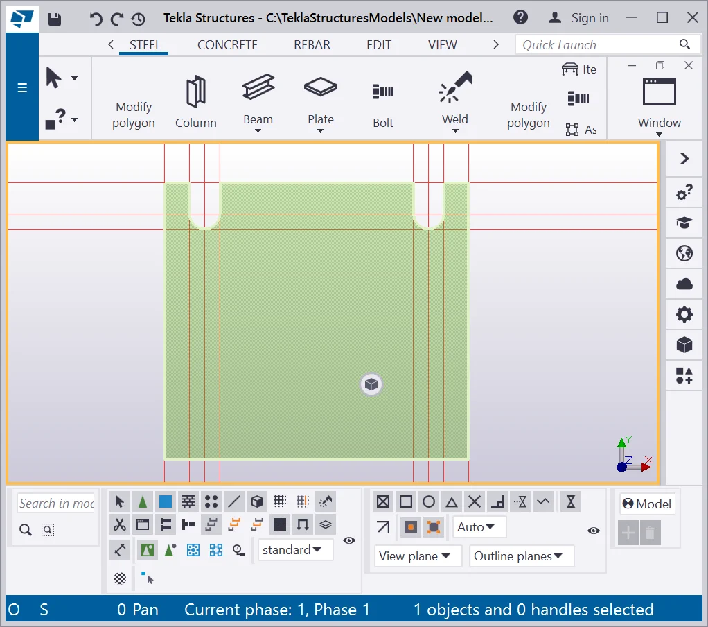
Select the points adjacent to the column wall by using framing schemes
Open the “Chamfer properties” menu (do not forget to hold on to the “Shift” key pressed to keep the entire points selection), and specify the type value to “Line” (hollow chamfer), X and Y values of 25mm.

It is one of the examples of using chamfers for modeling the reinforcing plates during structural engineering and design. All the similar structural parts are designed exactly by configuring chamfers.
Adding points
The first method for adding/deleting points
This method allows adding/deleting a point by specifying the points interval

Point two can be inserted to any place on the condition that the new contour
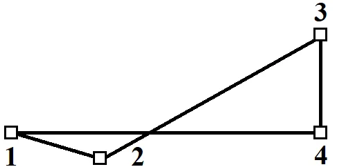
If a new contour does not possess the right building-up trajectory of
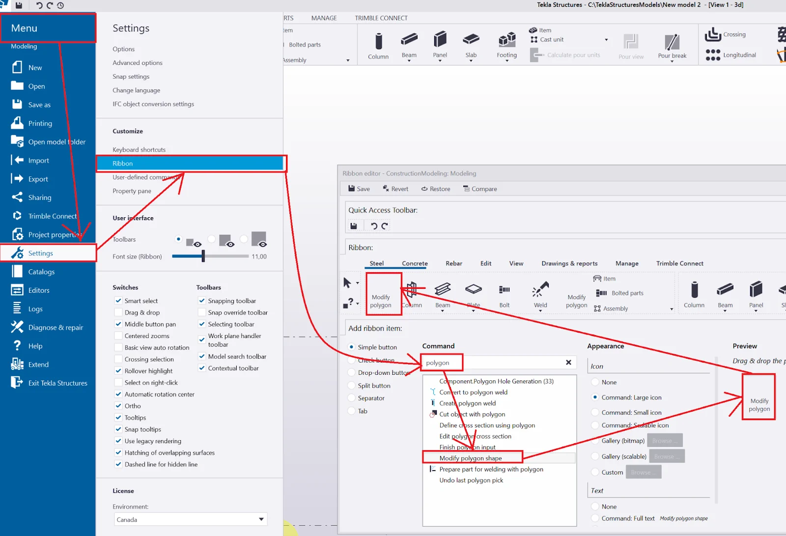
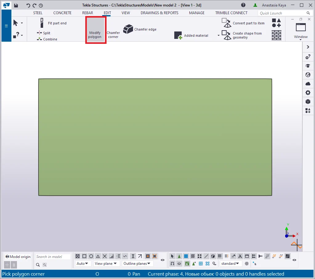
Setting the “Modify polygon shape” icon at the main menu tab
By default, the “Modify polygon shape” icon is not located
Therefore go to the “File”, “Settings”, “Ribbon”

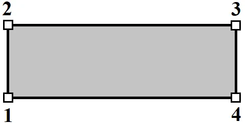
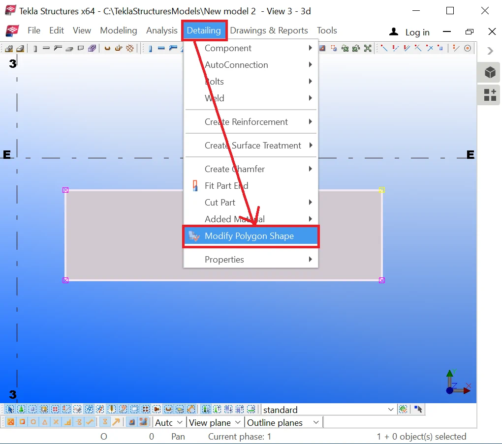
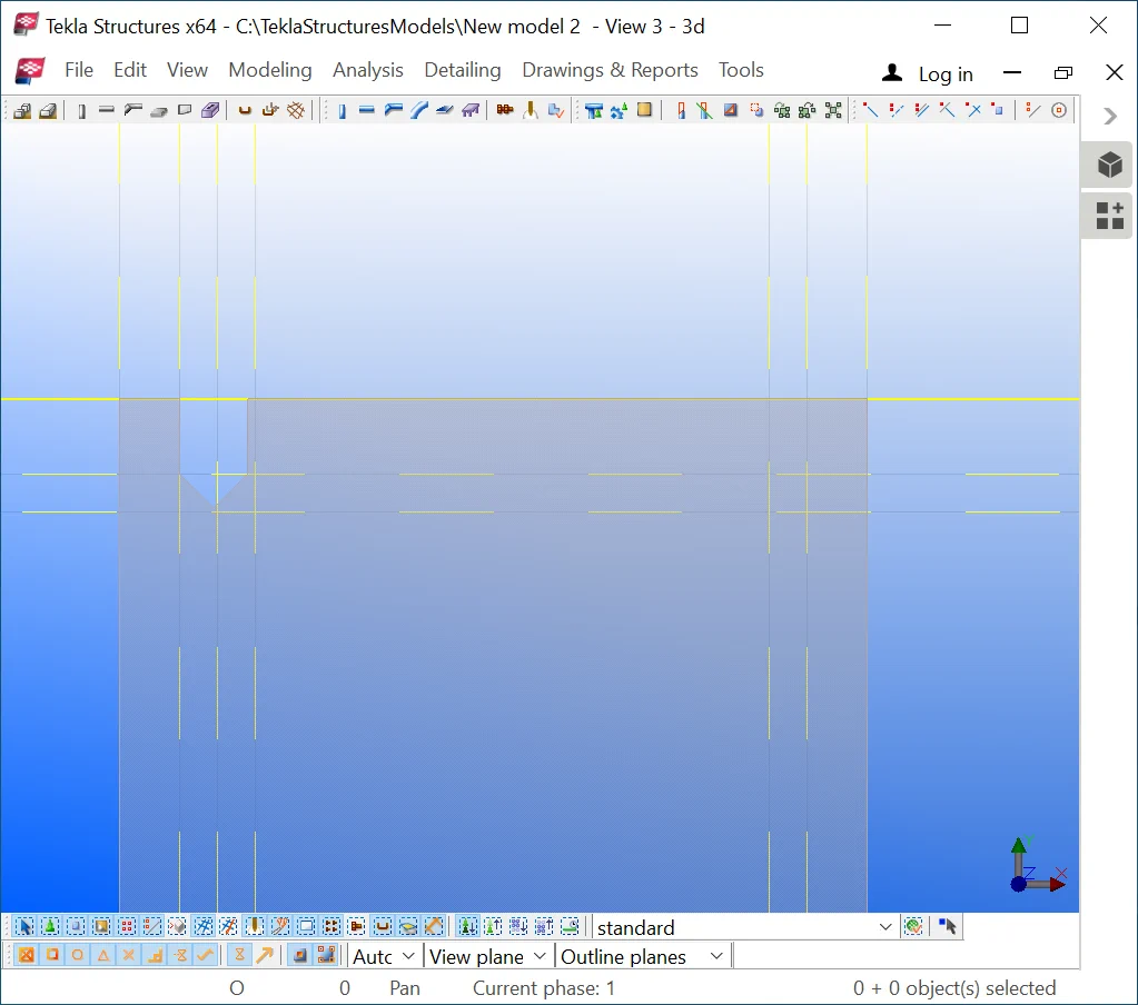
Create a simple contour plate (refer to the below picture).

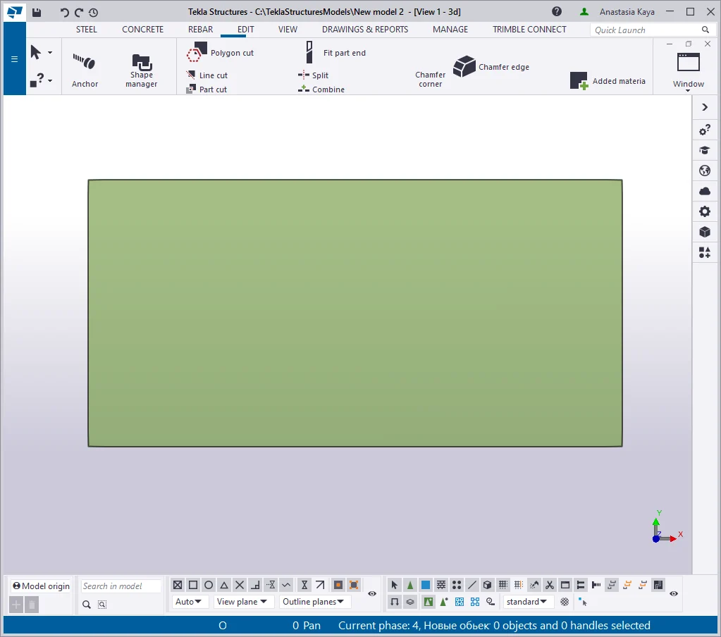
Select the plate and enable the “Modify polygon shape” tool.
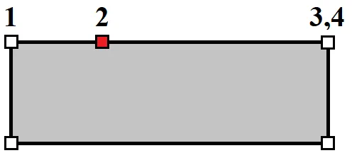
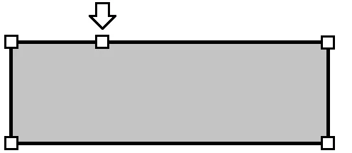
The scheme for adding new points to an already existing points range:
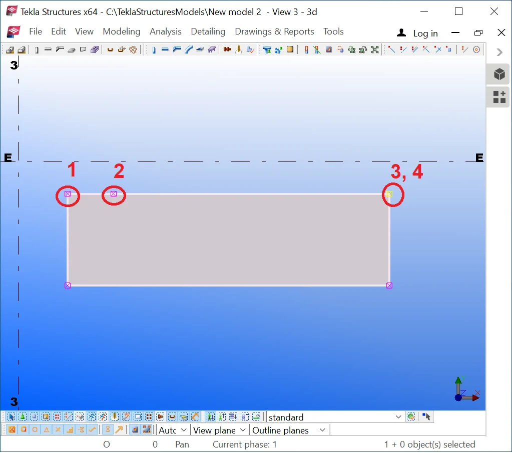

Exercise creating several points at the bottom side of the polygon .
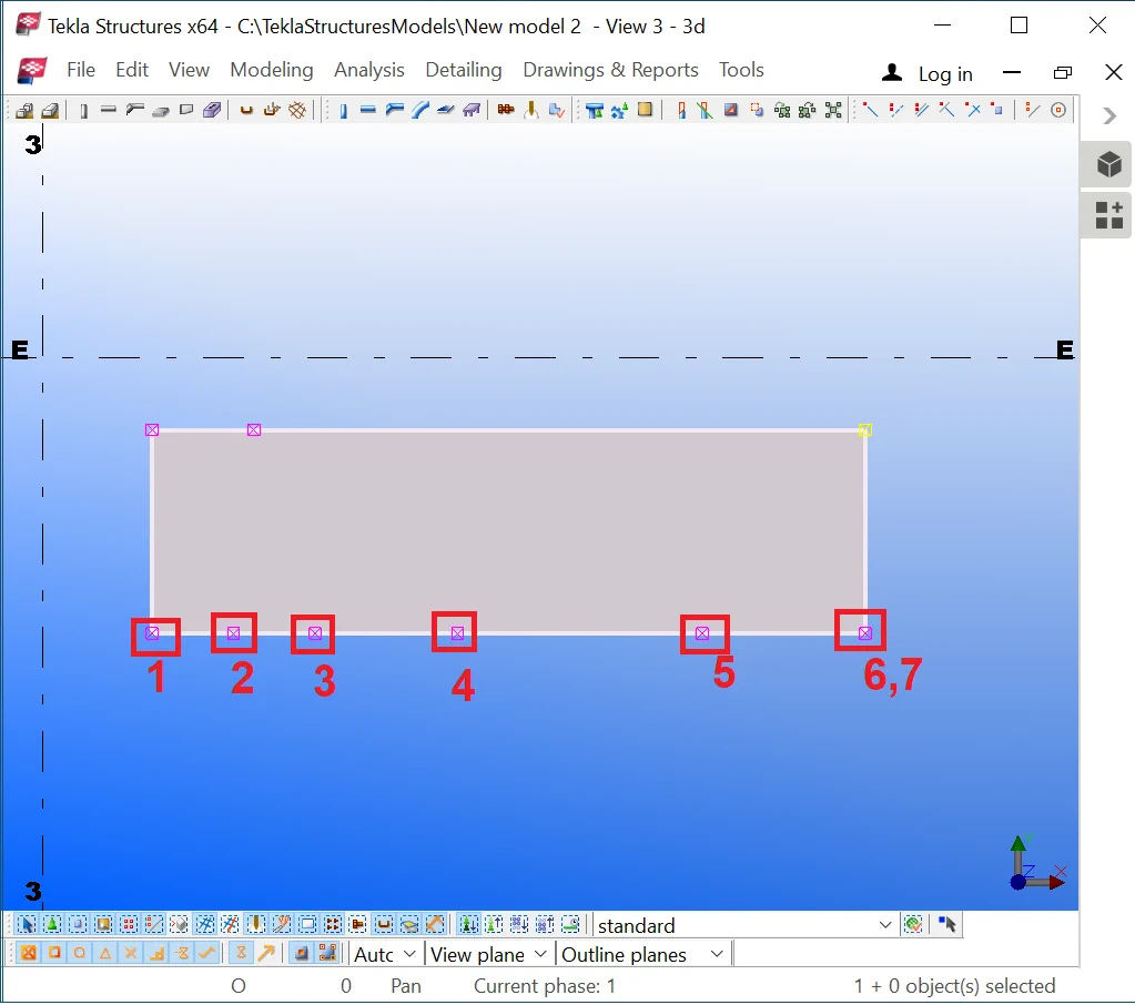
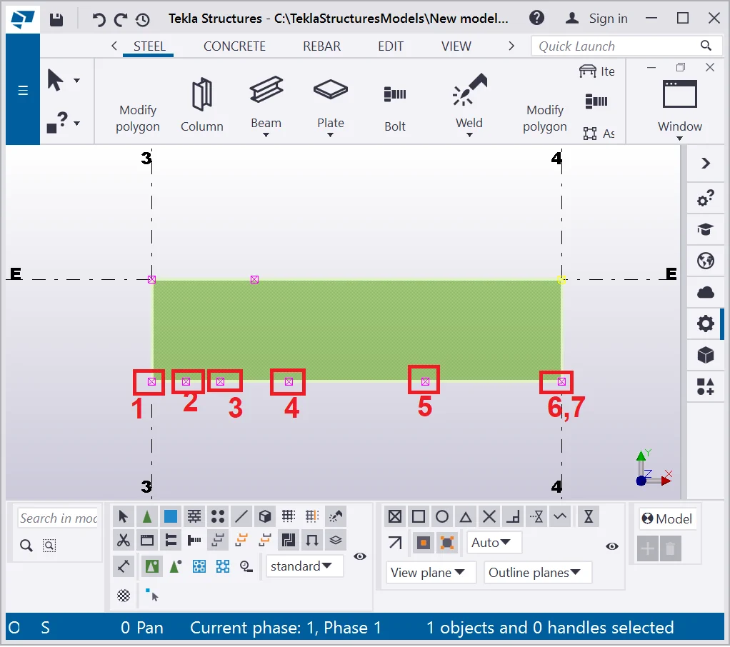
To delete a point/ a group of points apply the same tool in the following way: choose the points that form the range from where the other points will get deleted (marked by 1 and 2,3).
Thus all the points of the range will get removed.
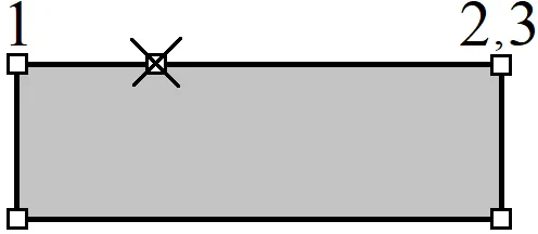
Exercise deleting the points from the bottom side of the plate.
Exercise this method for adding and deleting points on your own.
The 2nd method for adding /deleting a point
is executed by using the “Direct modification tool”
(v2021
 ,v21.1
 ).
).
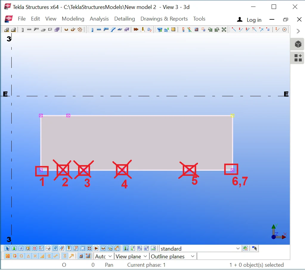
Enable the tool, thus when selecting the contour plate, its real points
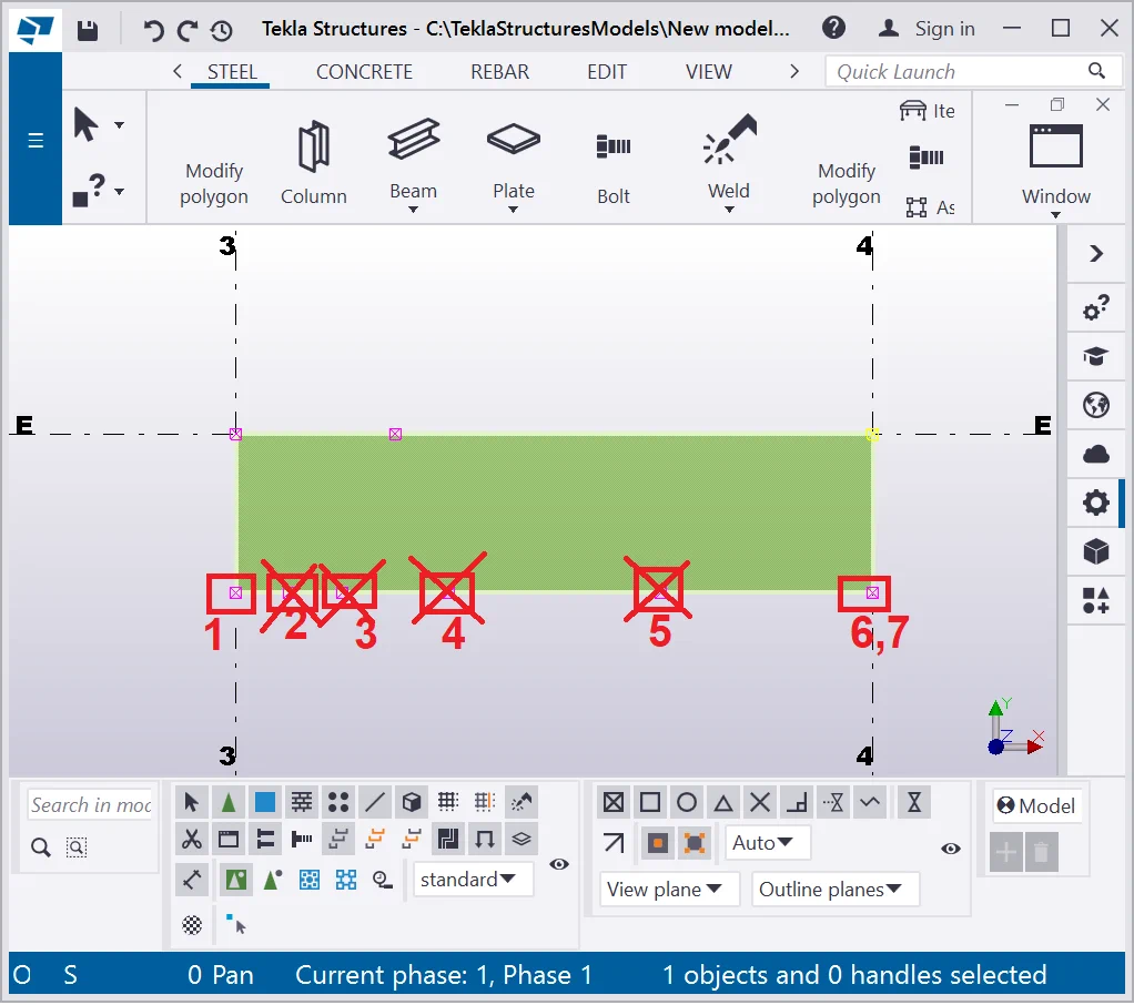
Dragging the midpoints by the mouse cursor turns them into real points.

Drag a point by using the mouse cursor as it is shown below:

Releasing the mouse button executes point displacement and the polygon


Note that in the range between the new point and the polygon angular point a new imaginary midpoint appeared. Let’s drag an imaginary point as it is shown below.
Pay attention to the displacement amplitude by axes X and Y.
The polygon changed its shape to as presented in the below picture:

Deleting a point in the “Direct modification” mode is done by a simple selection of the point and pressing the “Delete” key.

Deleting a point bounds the polygon side between the adjacent angular

To move a side of a polygon proceed as follows: select the side and displace
Changing the thickness value of a plate.
Rotate the view in the way to see the plate’s thickness. Select the plate and displace it at a required distance by the mouse cursor. Thus we are changing the plate's thickness.
This method is useful for illustrative purposes, though in practice it is not used, thus please switch off the “Direct modification” tool to avoid any accidental and unwanted updates.
Hereunder you can see the plate with the modified thickness value.
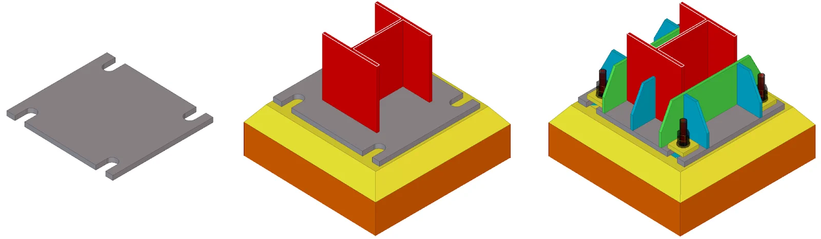
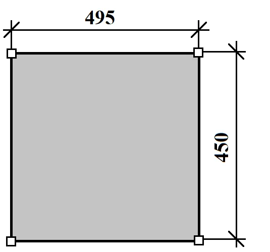
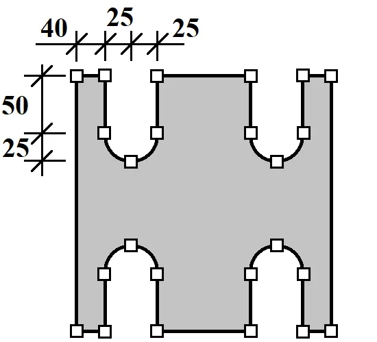
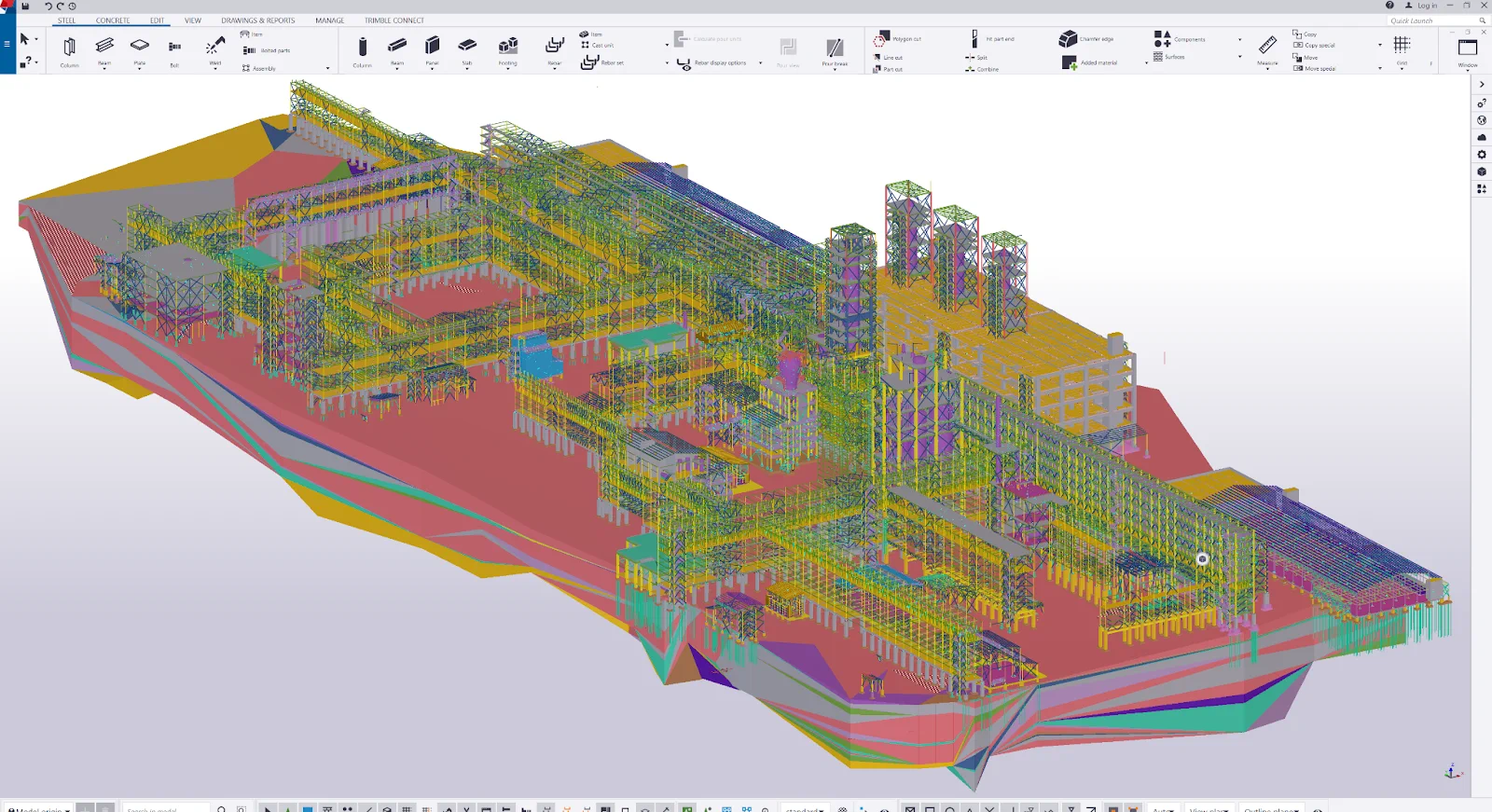
In the current chapter we will examine the ways of creating contour plates of a complex geometry. Refer to the above picture and the object marked with gray.
|
1st step - Create a rectangle |
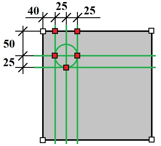
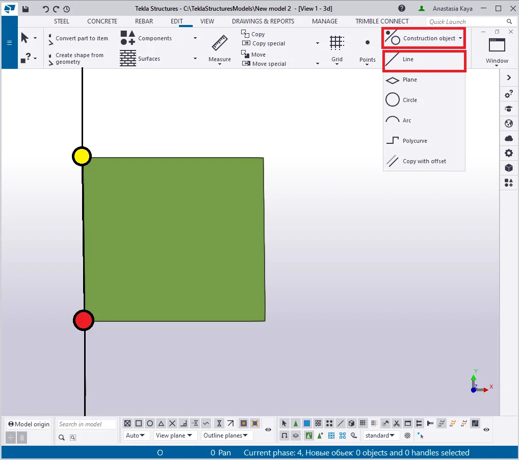
2nd step- Create construction lines |
3rd step - Add points |
|
|
|
|
|
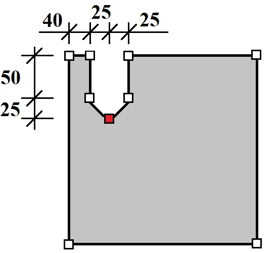
4th step - Select a point |
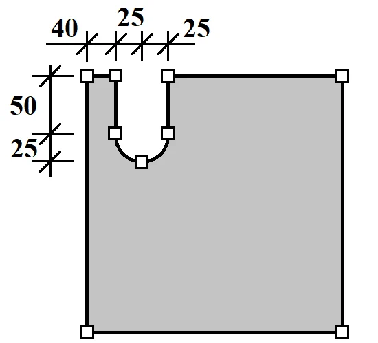
5th step- Create a chamfer arc point |
6th step- Repeat all the steps accordingly |
|
|
|
|
The 1st step

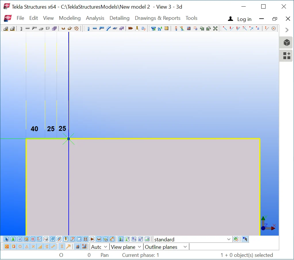
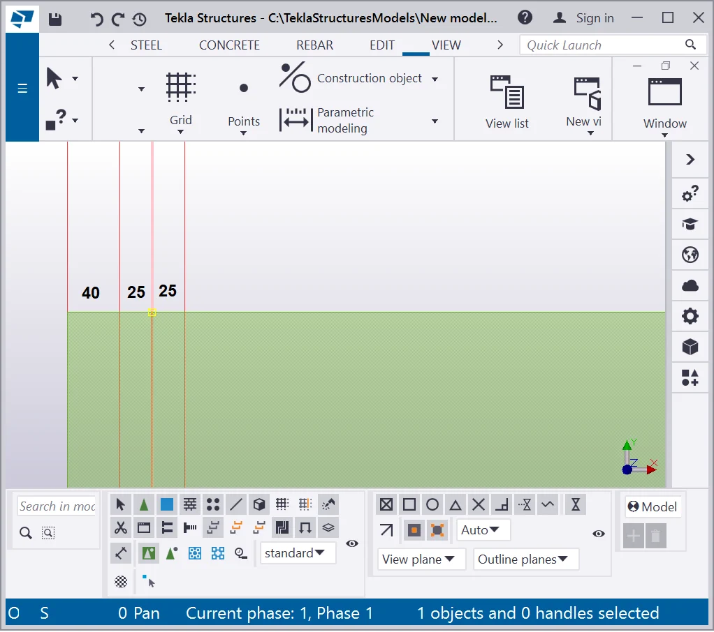
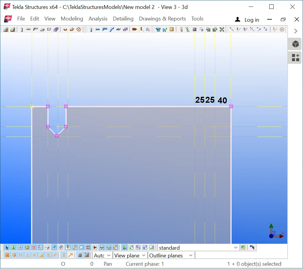
The 2nd step - Create construction lines . Add a vertical line along the side of the rectangular as it is shown below.

Copy-paste a line in the horizontal plane at the distance of 40mm by using


Repeat the above by pasting one more construction line at the distance

Repeat the above by keeping the distance between lines of 25 mm.
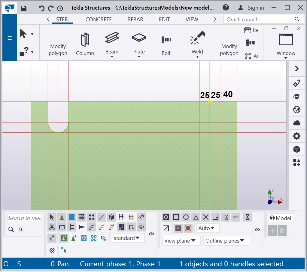
Draw up a horizontal construction line along with the top side of the
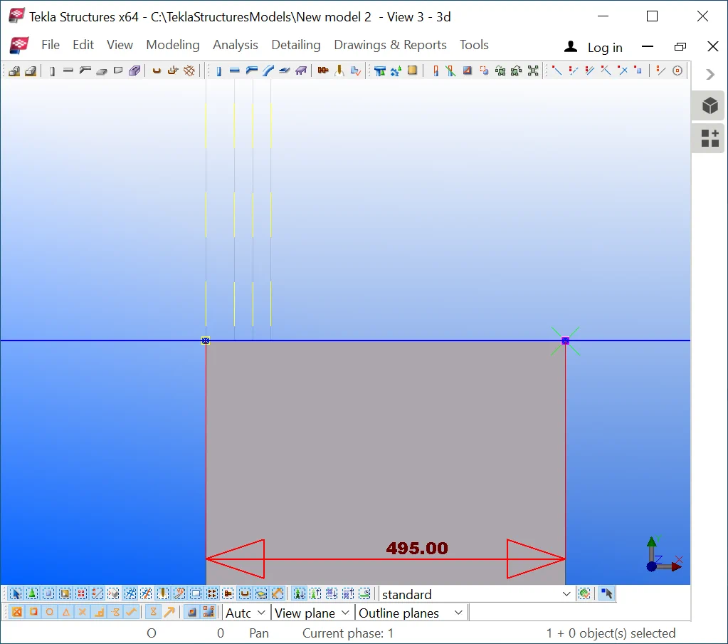
Copy/paste the horizontal construction line created at the distance of
Repeat the above by inserting a new line at the distance of 25mm from
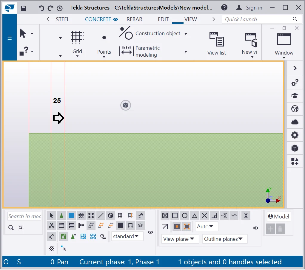
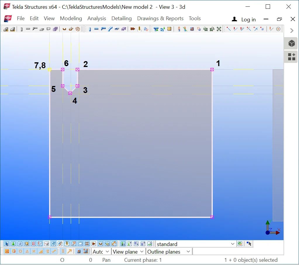
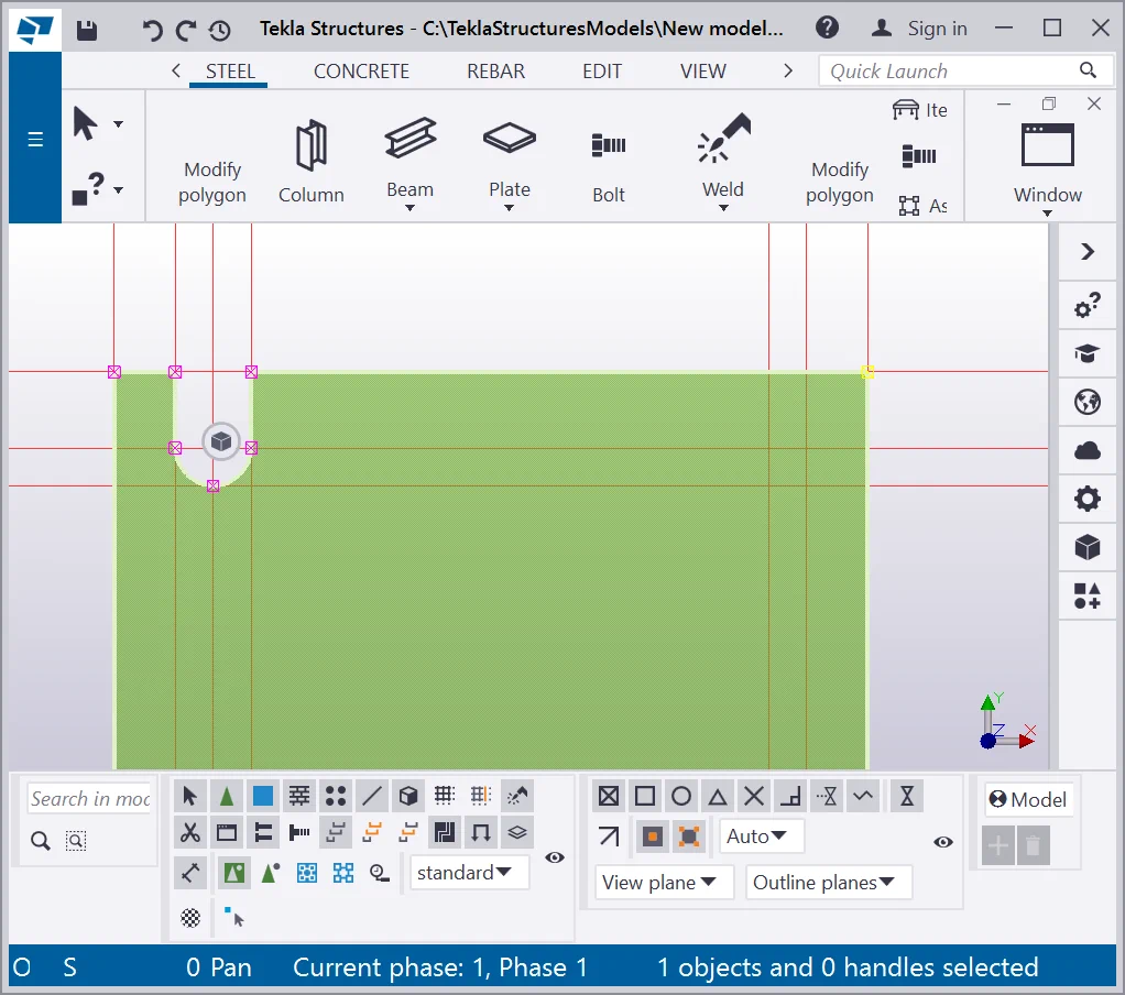
The 3rd step- create points
Now we have all the required intersection points to create a cutoff. Make sure that the “Direct modification” tool is switched off. (v2021 ,v21.1 ). Create construction points by using the respective tool. Refer to the figures presented below:
If your result is similar to the one presented below, then change the
The reason for failing on changing the contour plate shape stands for the fact that TS keeps the sequence of the points with respect to the sequence of the points of the initial plate.
The 4th step - Select a point
In TS it is important to keep the sequence of the points with respect
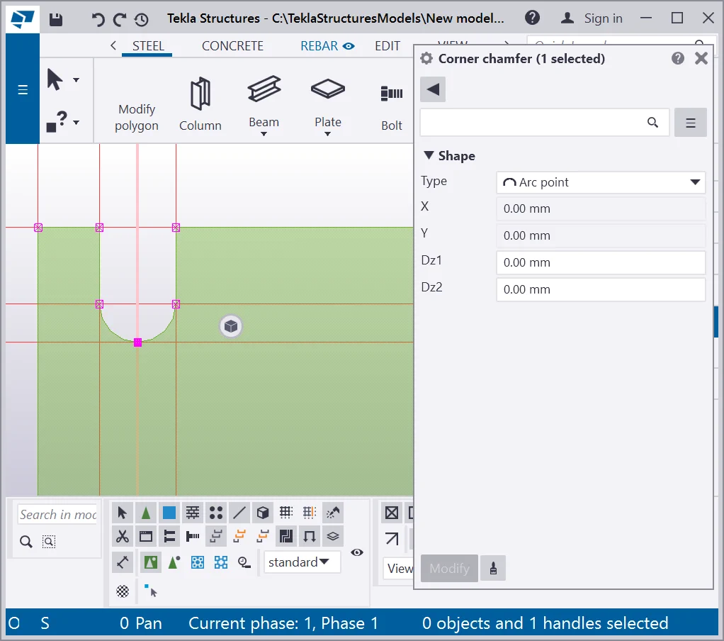
The 5th step - Execute the chamfer rounding
Open the “Chamfer properties” dialog window and specify the

The 6th step - Repeat the above steps
Create the next cutoff by mirroring the construction lines created.
Note that you should copy/paste the lines along the plate edge to the
Create the points by yourself using the same algorithm and set the similar
To create bottom cut-offs let’s use the second method for adding
points. To proceed on it, switch on the “Direct modification”
tool (v202 1
,v21.1
)
Insert new horizontal lines by mirroring the ones above to get intersections with the vertical lines, as required. Further, select the plate and recourse to the “Polygon shape modification” tool, drag imaginary midpoints, and set them to real. Keep on going until necessary alignment is achieved.
Note that maximizing the TS view scale reduces moving steps.
The closer the view is, the smaller the step is, facilitating the new

You should get as it is shown below:
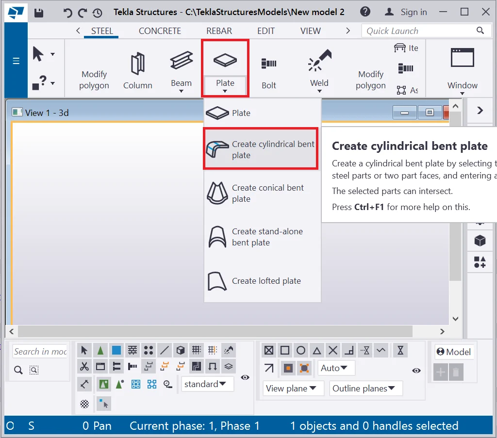
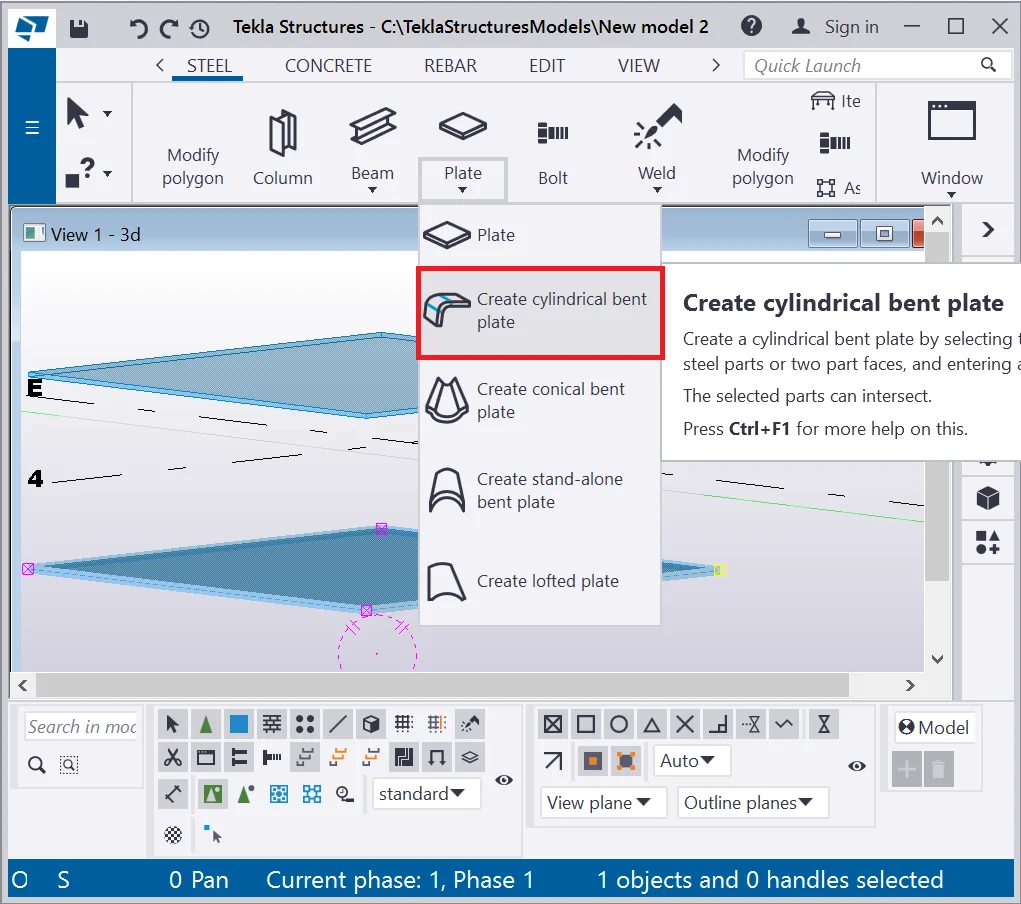
The “Cylindrical plate” tool allows drawing curved cylindrical
You can access the tool at the “Plate” drop-down menu. Let’s examine it, by creating two standard plates and uniting them into one employing this tool.
Present Tekla Structures version is not available on the “Create cylindrical bent plate” tool
Create a plate with dimensions of 1000x1000mm. Choose an arbitrary profile
Present Tekla Structures version is not available on the “Create cylindrical bent plate” tool
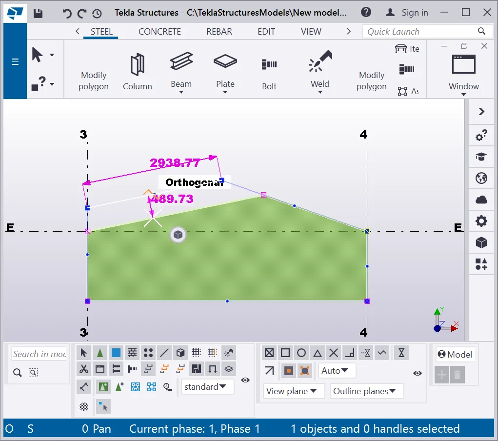
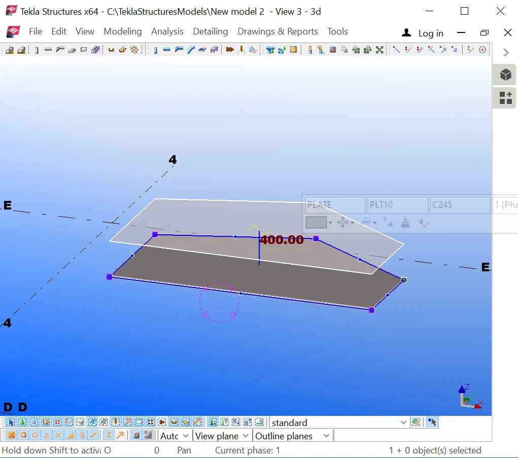
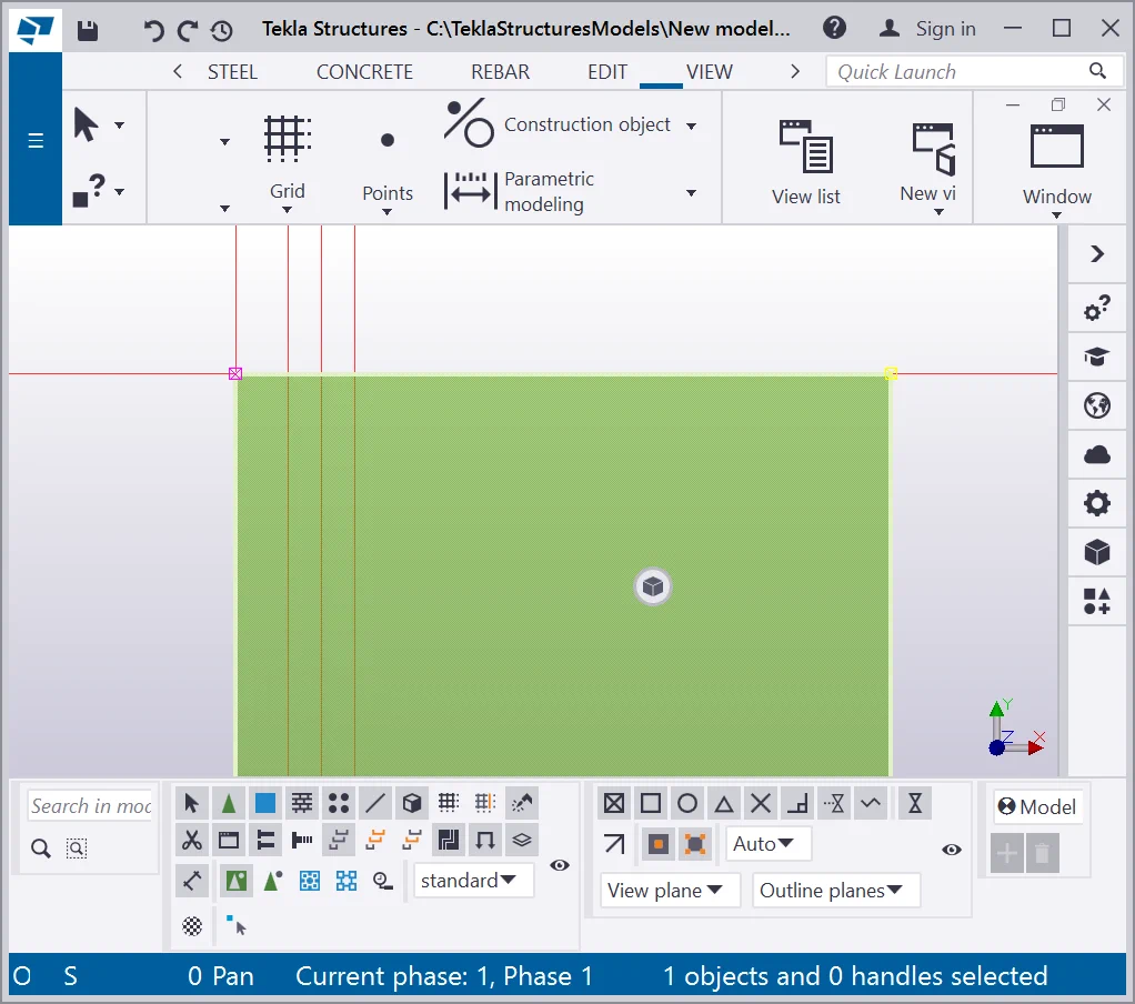
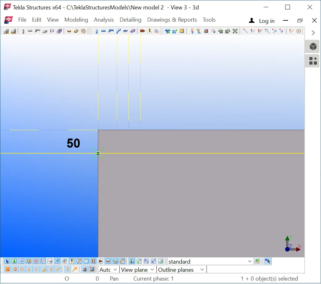
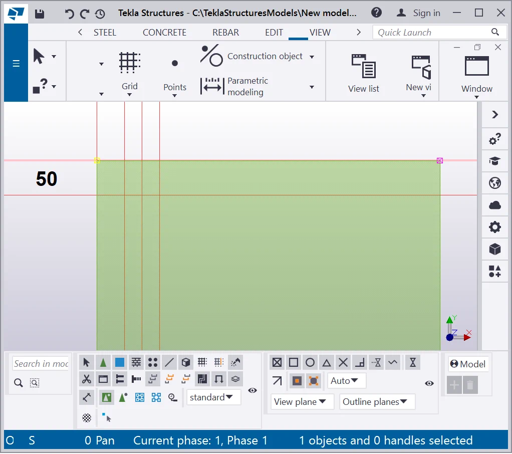
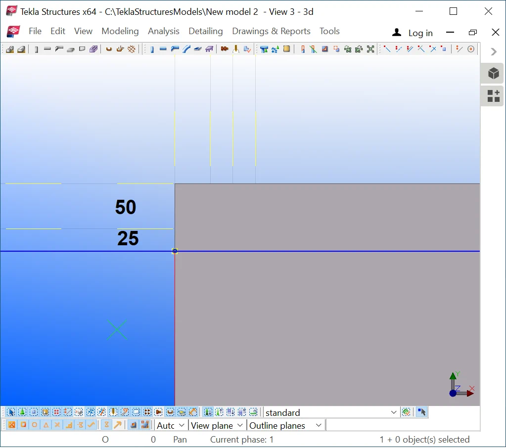
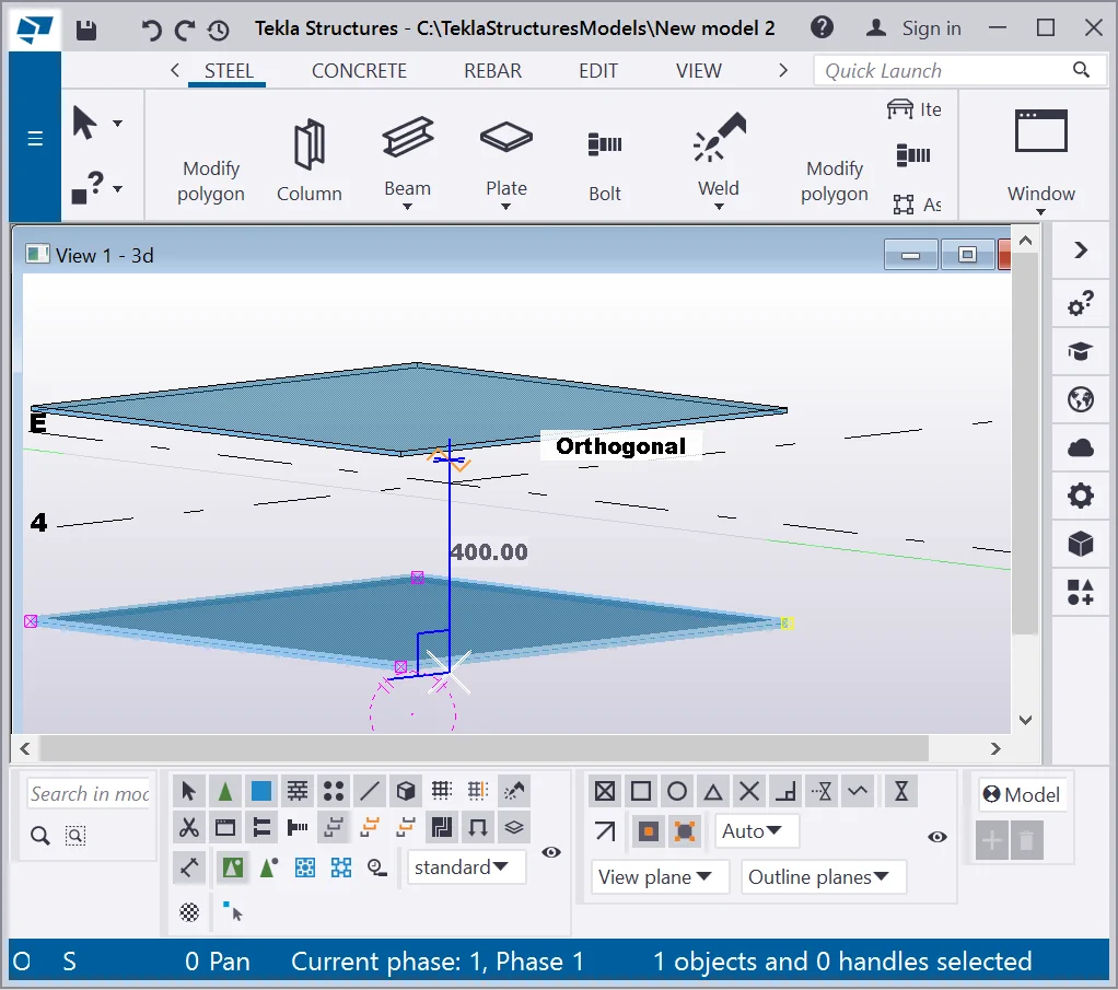
Rotate the view in the way to copy the plate vertically by the Z-axis: select the initial plate, press Ctrl+C and drag it at 400mm vertically. Make sure the orthogonal regime is switched on.
Present Tekla Structures version is not available on the “Create cylindrical bent plate” tool
Select the “Create cylindrical bent plate” tool.
Present Tekla Structures version is not available on the “Create cylindrical bent plate” tool
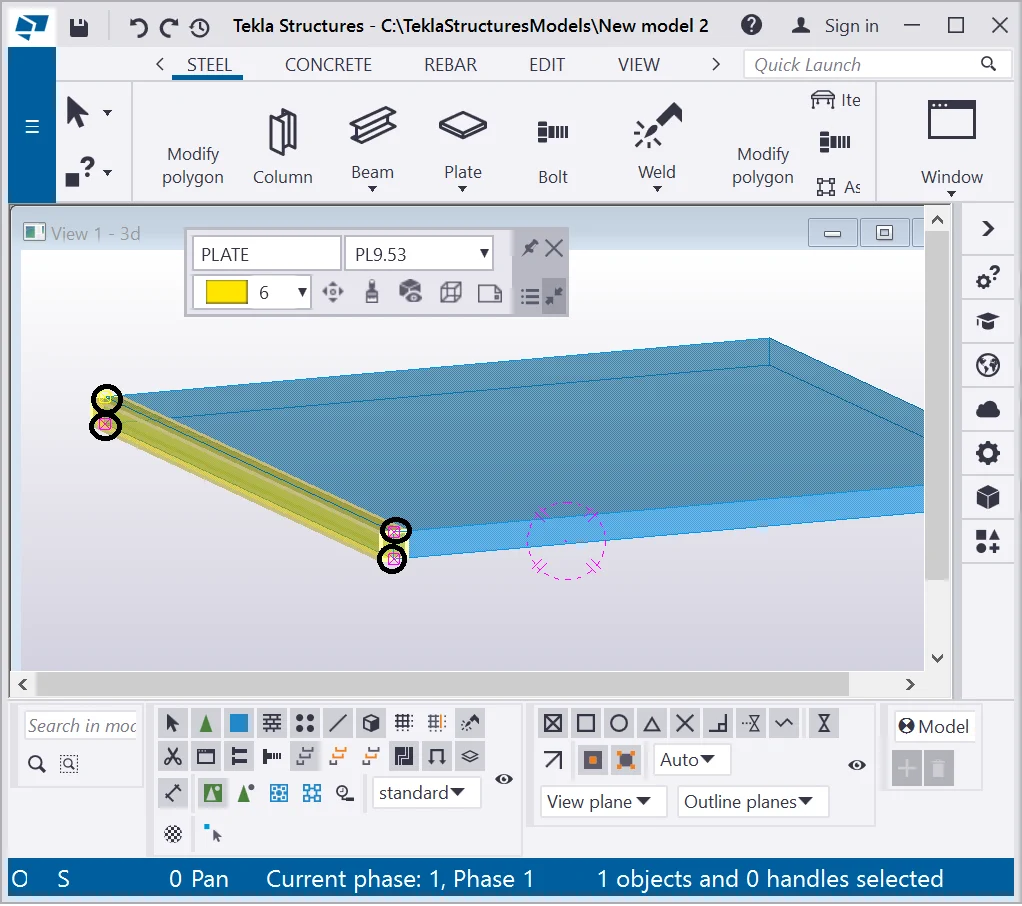
In the dialog window appeared, indicate the snapping type “By Faces”,
Present Tekla Structures version is not available on the “Create cylindrical bent plate” tool

If all operations have been carried out correctly, then you have got an
Note that initially, we had two plates as two separate objects.
After using the “Create cylindrical bent plate” tool, the
Present Tekla Structures version is not available on the “Create cylindrical bent plate” tool

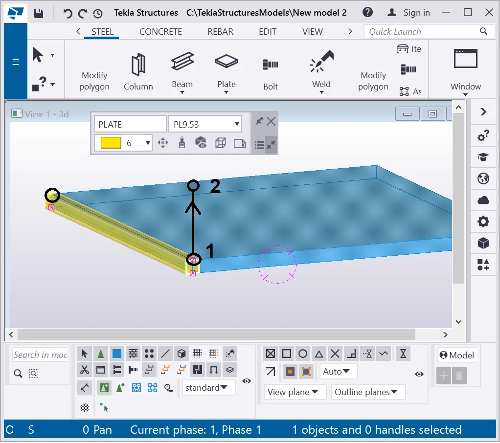
Let’s exercise using the tool by activating the “By Parts”
Present Tekla Structures version is not available on the “Create cylindrical bent plate” tool
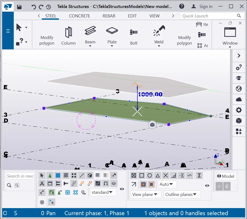
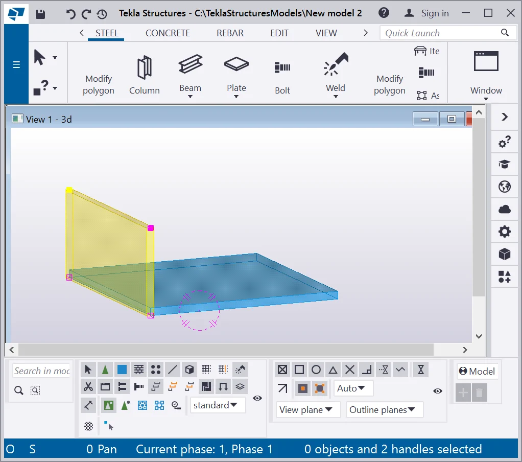
Allocate the second plate perpendicularly to the initial one.
Present Tekla Structures version is not available on the “Create cylindrical bent plate” tool
To create the second plate, select the top points of the initial object
Present Tekla Structures version is not available on the “Create cylindrical bent plate” tool
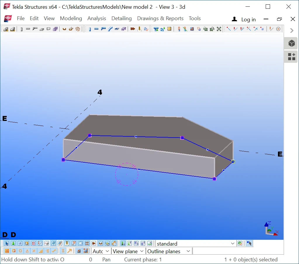
As a result you will get two perpendicular not intersecting with each
Present Tekla Structures version is not available on the “Create cylindrical bent plate” tool
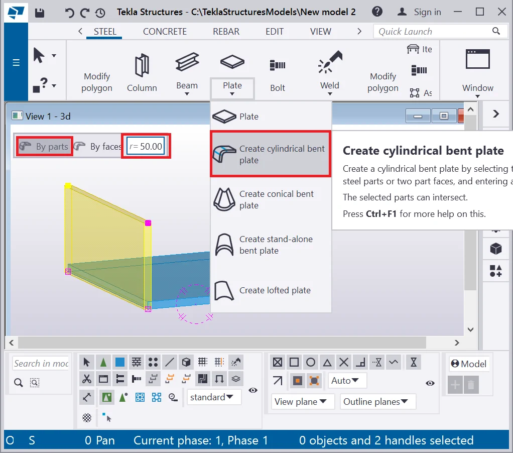
Go to the “Plate” tool drop-down menu and select the “Create cylindrical bent plate” option, activate the “By parts” snapping type, and set the radius value of 50 mm into the adjacent box.
Present Tekla Structures version is not available on the “Create cylindrical bent plate” tool
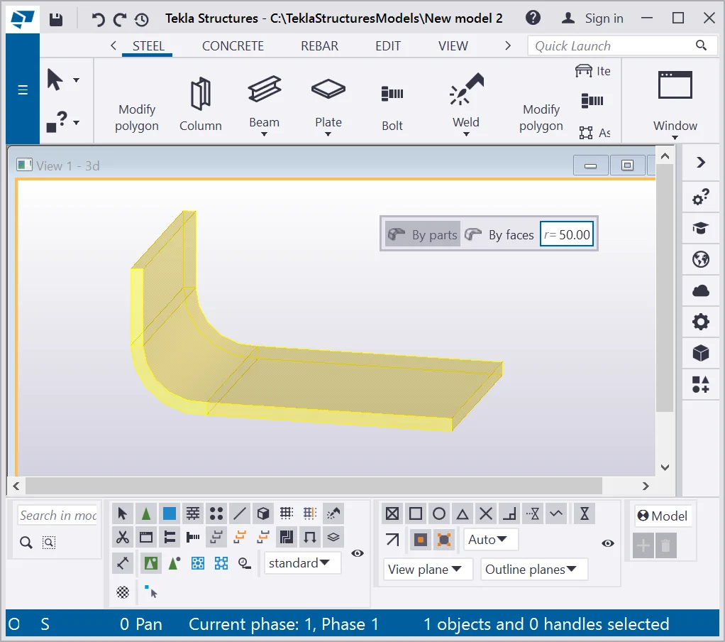
If you carried out all the operations correctly, then your results are
Present Tekla Structures version is not available on the “Create cylindrical bent plate” tool
In practice, this manipulation is substituted with the M-beam profiles. The object’s parameters are similar to standard plate variables.