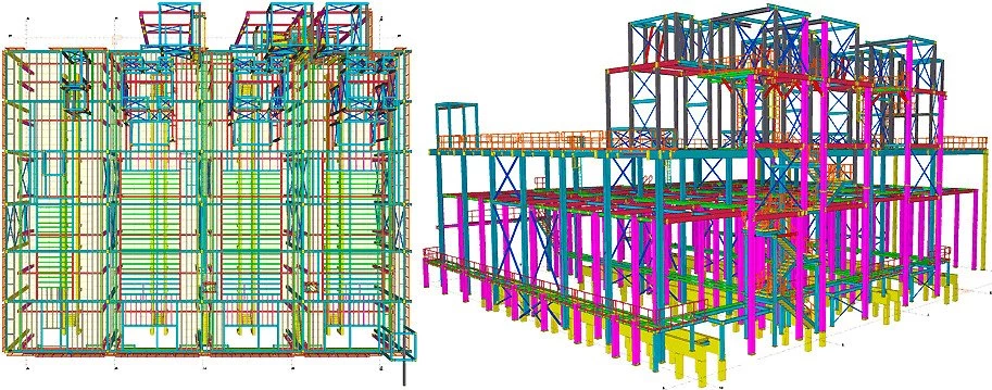
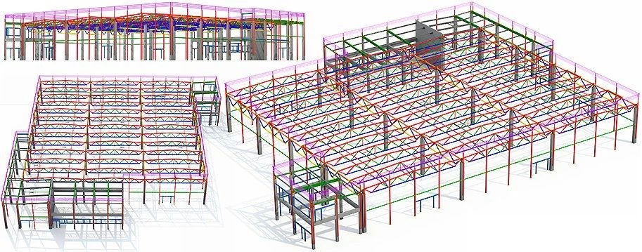
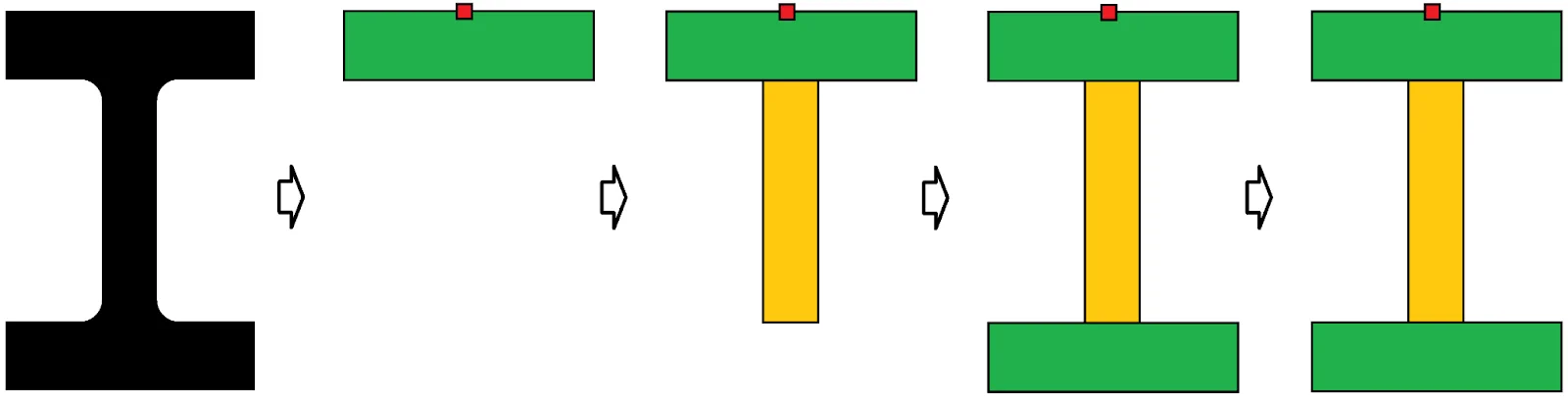
These are special beam-type frequently used in construction.
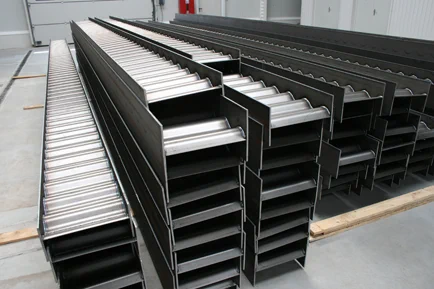
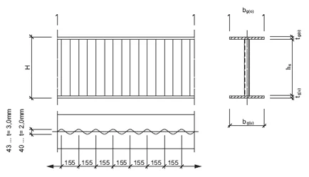
Create such a beam type using the Tekla Structures software.
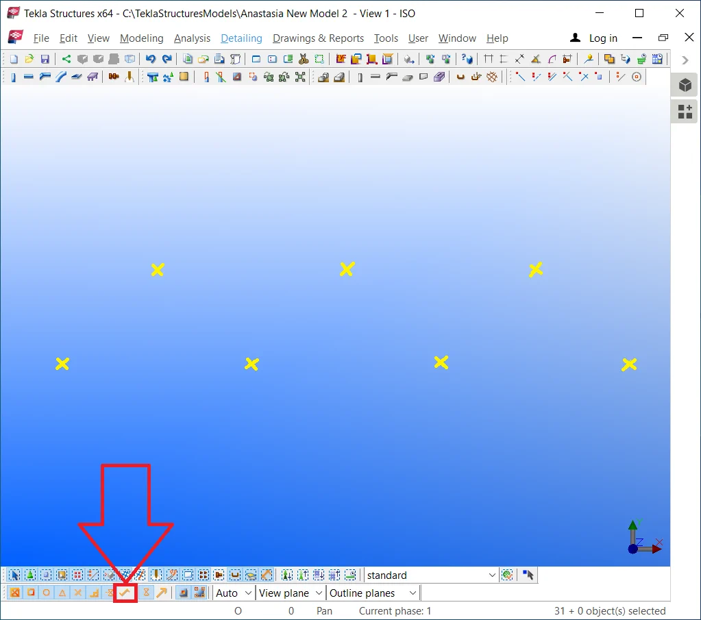
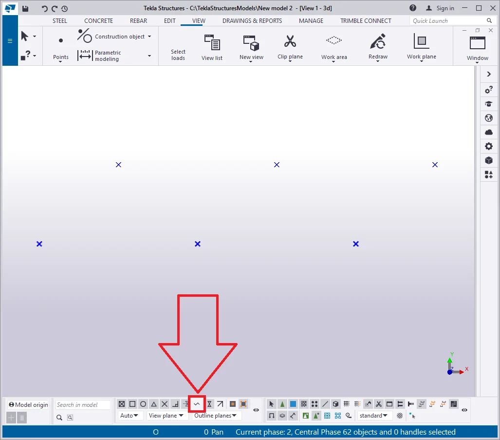
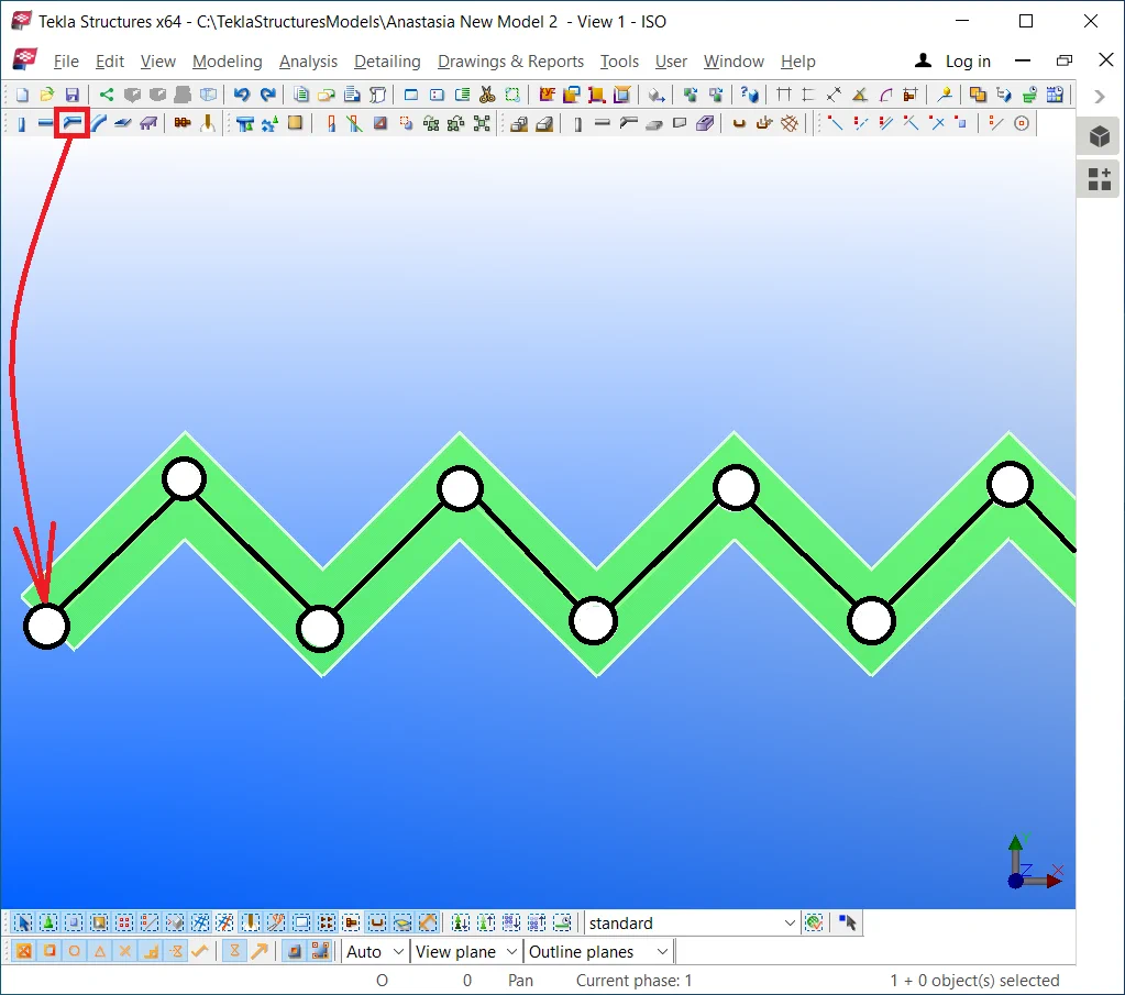
Go to the "Top view". By using the construction geometry tools,


Switch off the “Snap to any position” tool to avoid missing
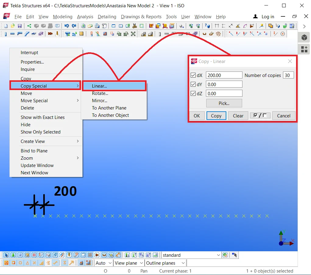
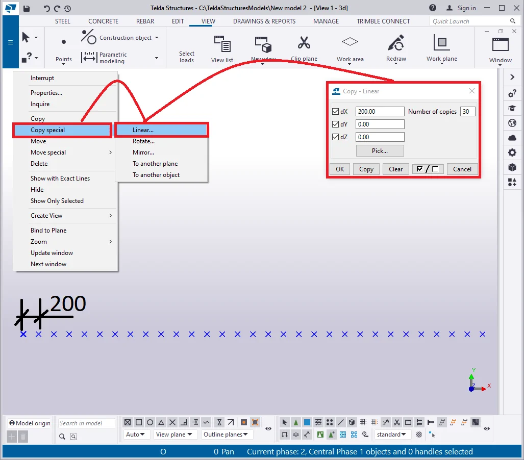
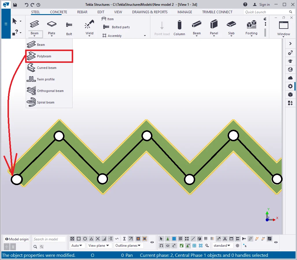
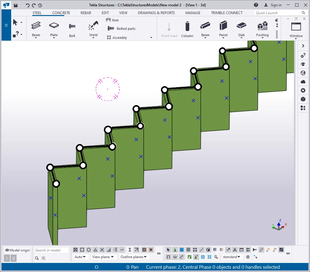
By means of the “Polybeam” tool, let’s trace a beam, passing through all the 62 points. Upon completion, do not forget to press the mouse wheel button or the “Space” key to finalize the operation.
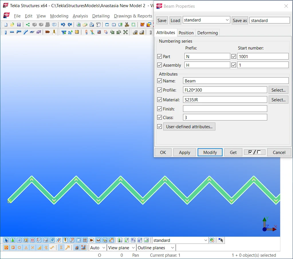
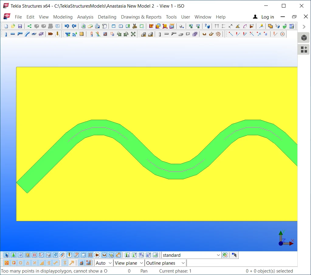
It is important to mention that such a type of beam has several limitations: its width shall not exceed its length value. Let’s check out the situation when the width profile value is admittedly large enough.
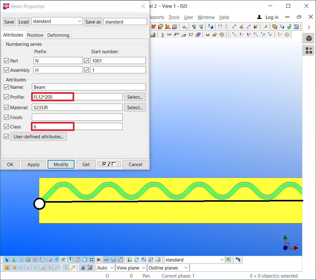
Switch the profile value of polybeam to the rolled metal with dimensions
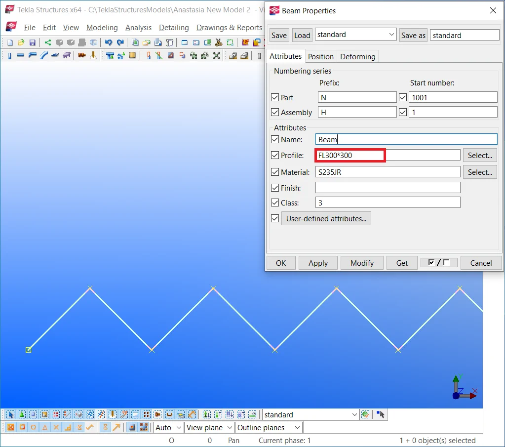
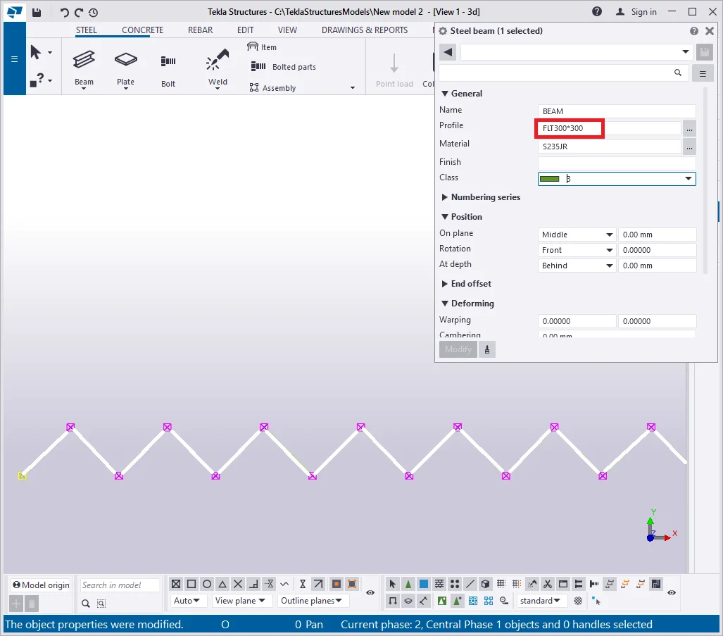
As you can see from the above, it is not possible to create a polybeam of such a geometry. The software renders the polybeam as a thin line, denoting there is a must to change the profile settings.
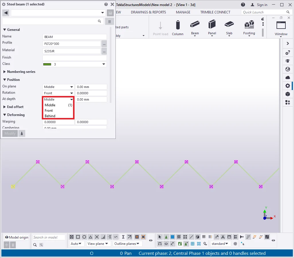
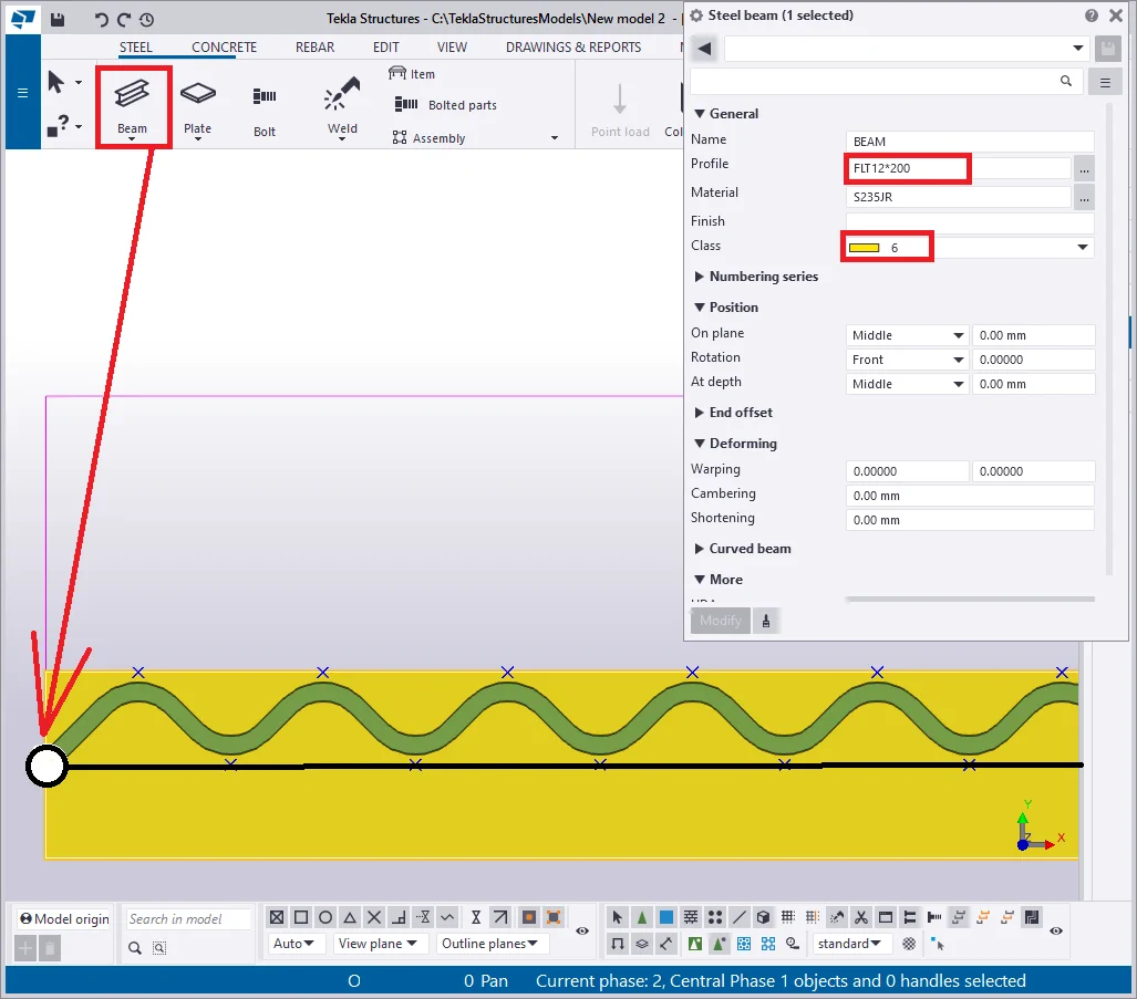
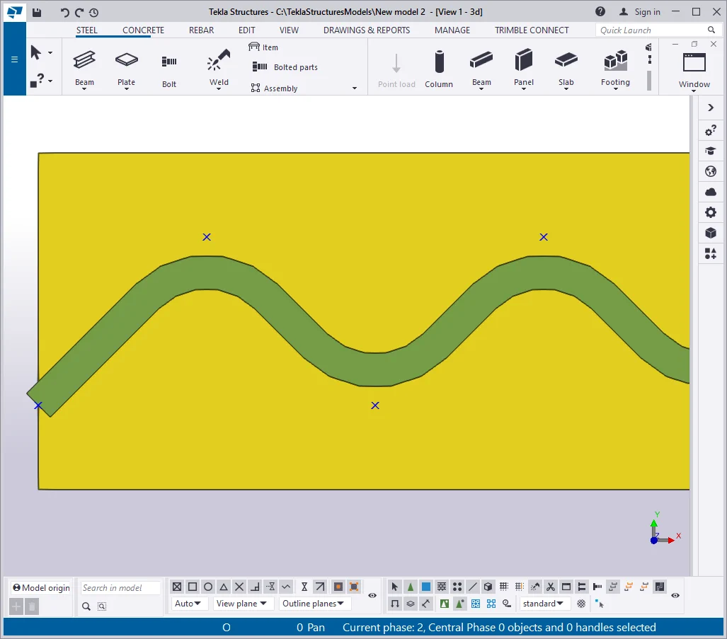
Set out the profile type to a reasonable value as “—20*300”.
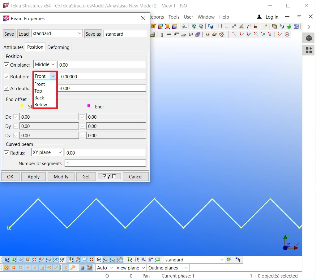
If still the profile geometry is shown as erroneous one, then there is a need to set out the “Rotation” parameter value by turning it at 90 degrees, as now the profile is of 300 mm thickness.

Toggle between the values of the“Rotation” field to get a clear understanding of the typical geometry error and the factors causing it. Depending on the current view settings, the “Rotation” field values might work in different ways.
Execute the configuring by yourself.
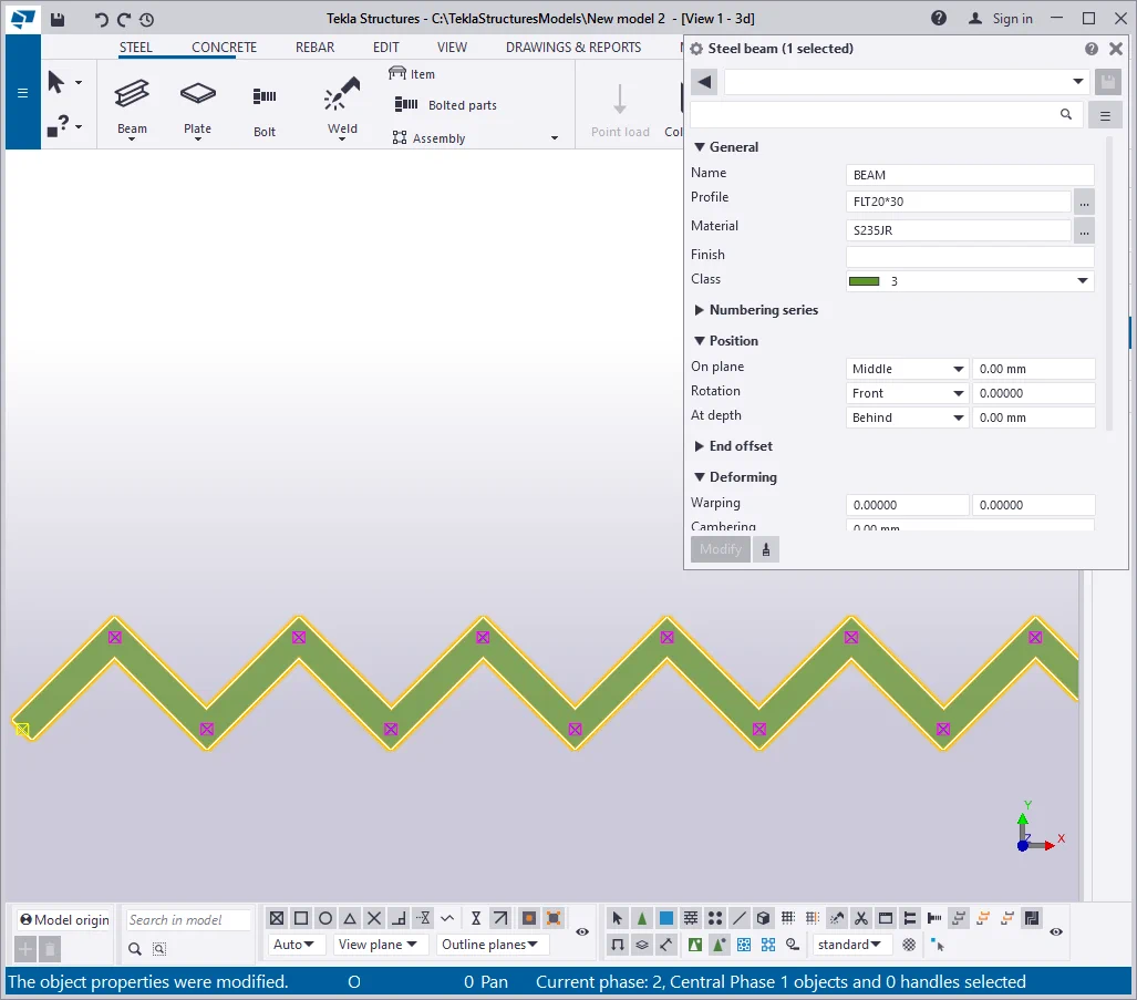
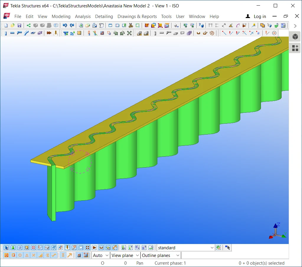
Compare your results to the below:

Shift the I-beam at 50 mm in the upwards direction by using the Ctrl+M
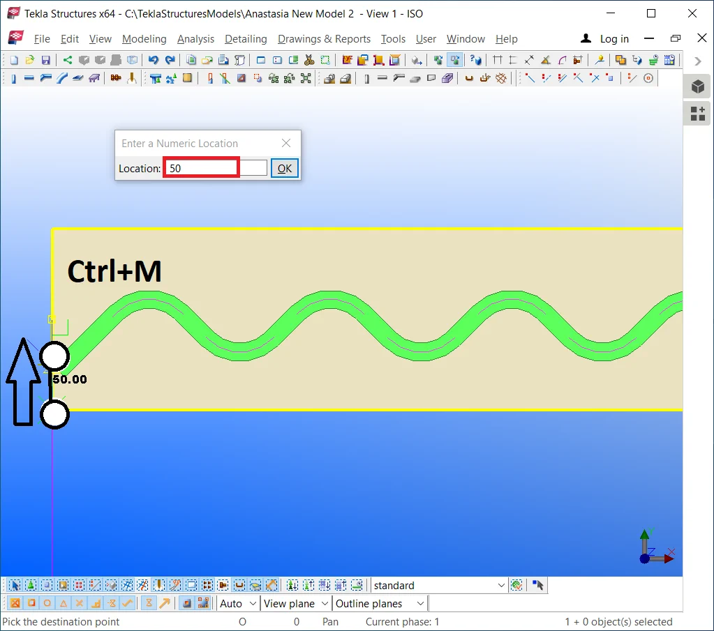
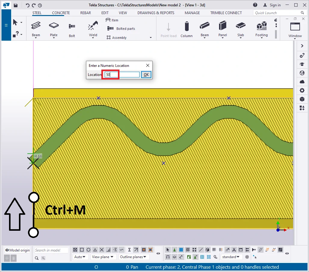
Now, the polybeam flange is located right at the profile center.
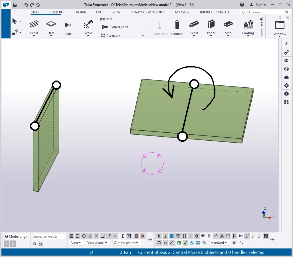
Rotate the view in the way to see the beam's wall and flange in 3D. It comes evident that the profile of the beam wall has no vertical offset.
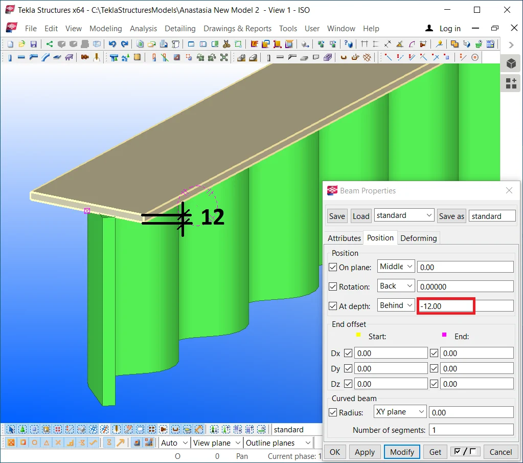
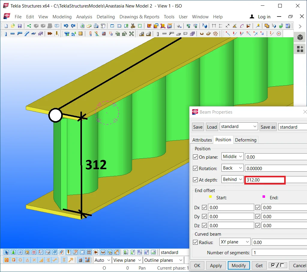
Go to the "Polybeam properties" menu and indicate the offset value equal to the profile thickness according to the scheme of a straight line beam with a common reference line. See below:
Set the offset value equal to 12 mm.
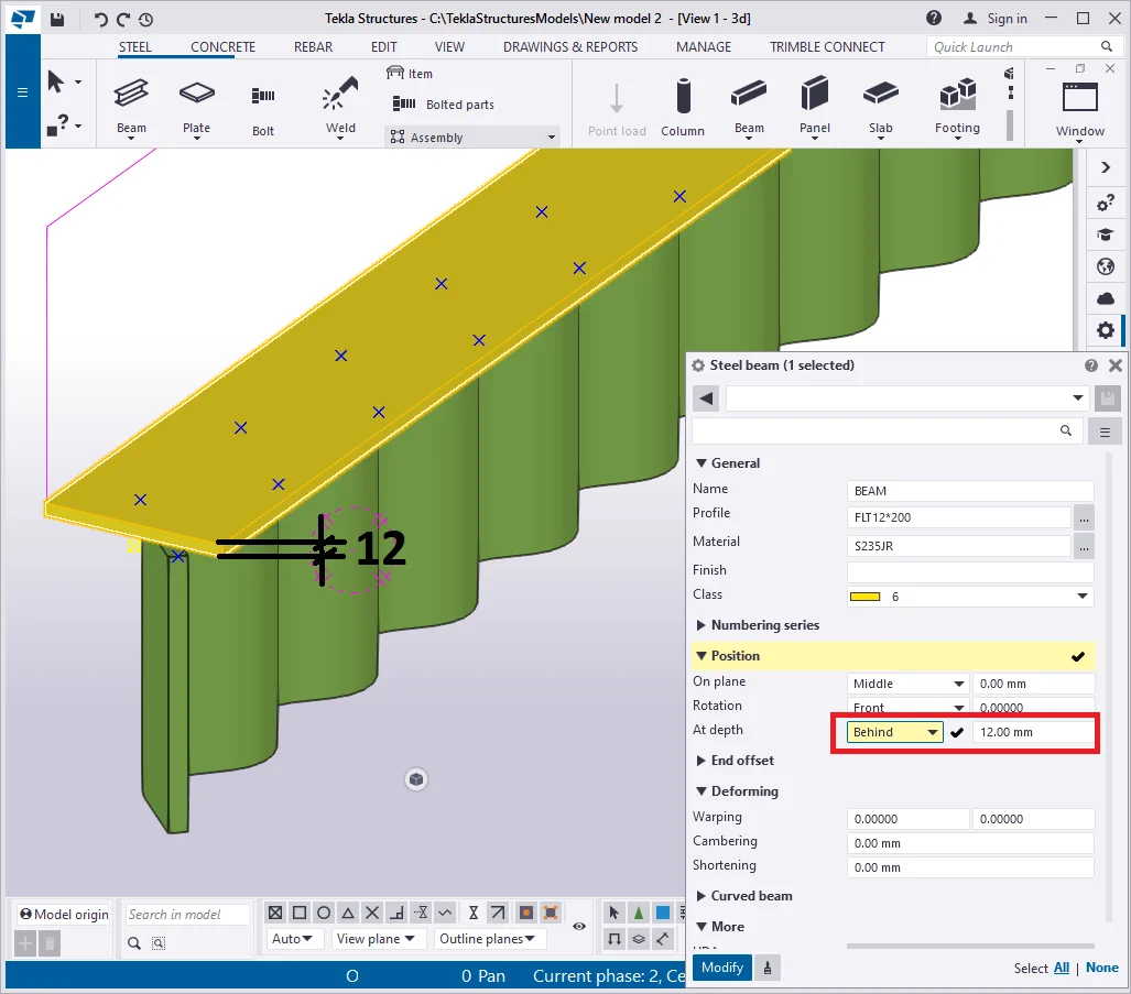
Copy the top plate over the initial plate position and configure its offset

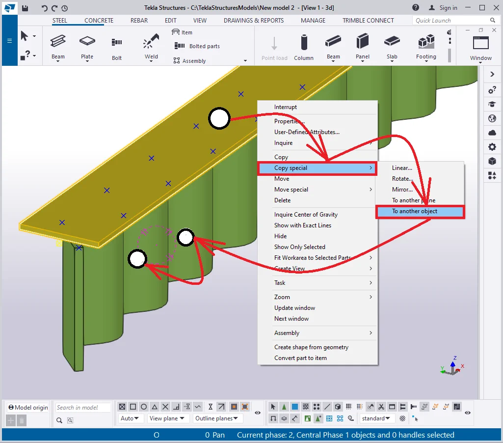
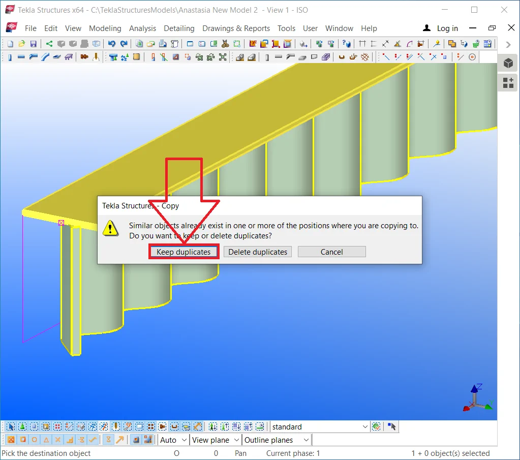
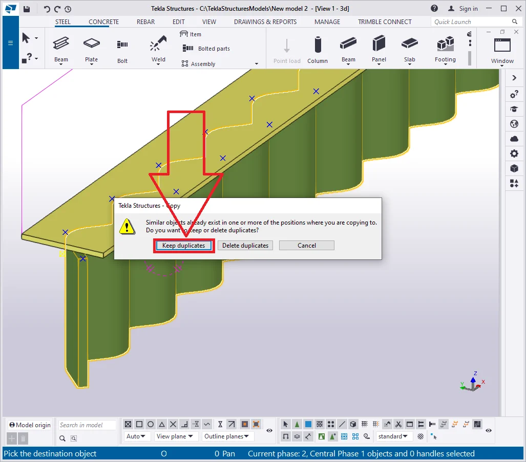
Upon executing the above, the TS will pop up an alert message about the duplicates created, as the duplicates are causing doubling the weight of the model and drawings overlapping.
Confirm creating duplicates by pressing the “Keep duplicates”

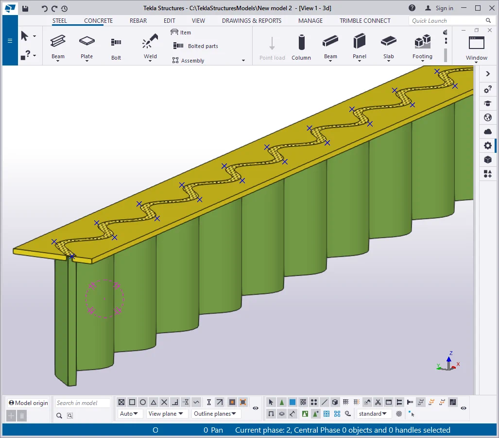
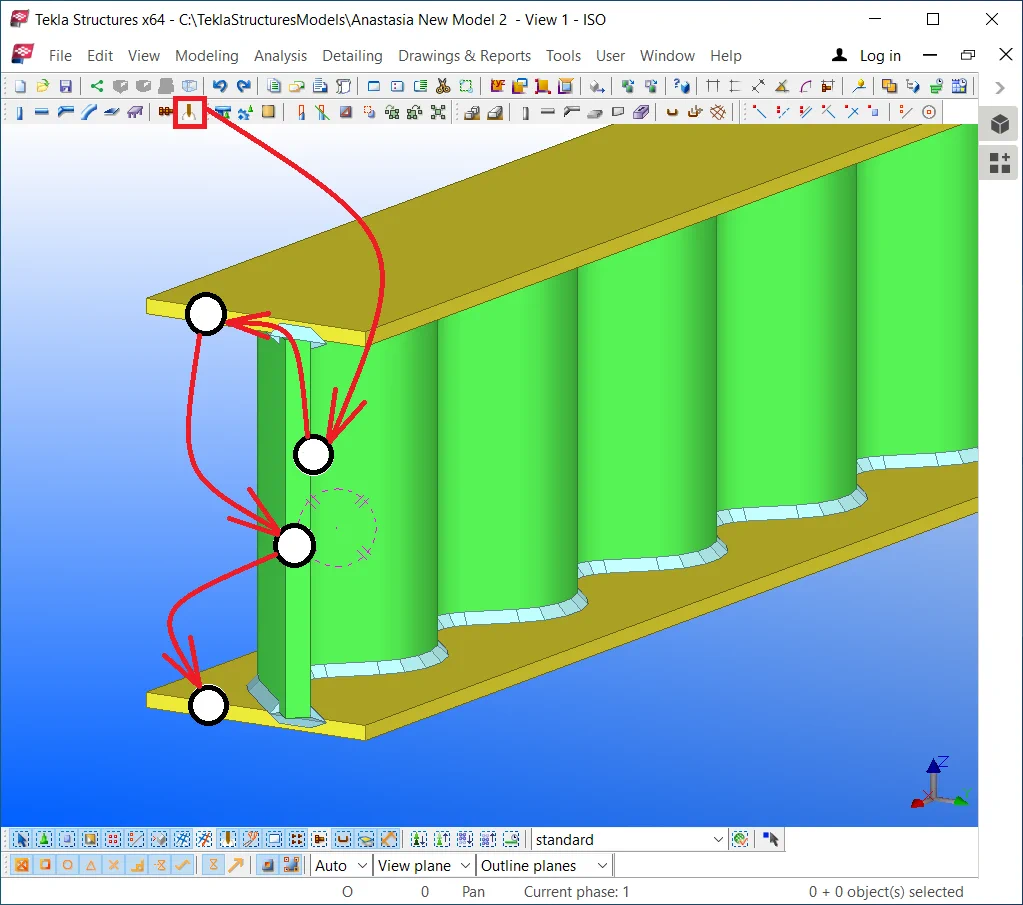
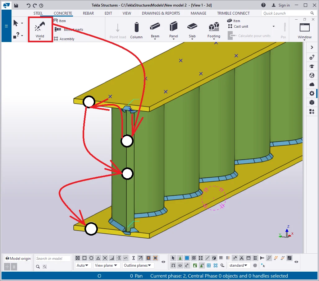
The only step left to be done is welding on the parts. Indicate the I-beam
Note that in the current case, only the “Around” type
Thus we have created a SIN beam. Other such beams when running a project