Enabling the “Cut object with polygon” tool creates a plate analog added material object. In other words, it is possible to abstract a part with the shape of a plate of any object.
Hereinafter let’s refer to this tool as an added material plate, for further convenience based on the similarity of its properties with the plate's object.

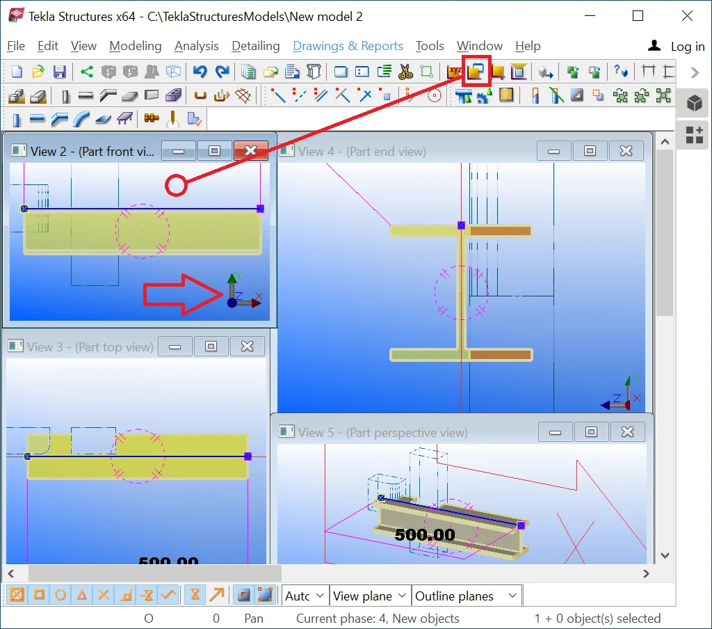
Create a beam of 500 mm length.
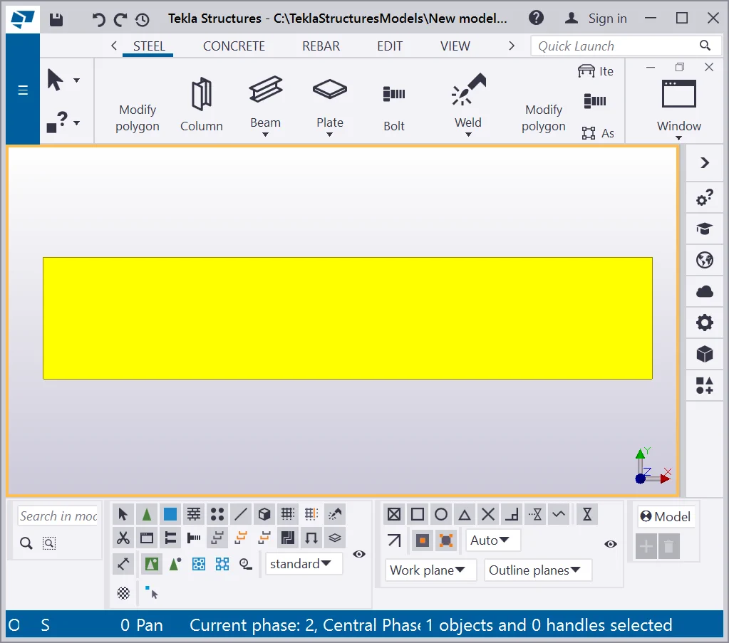
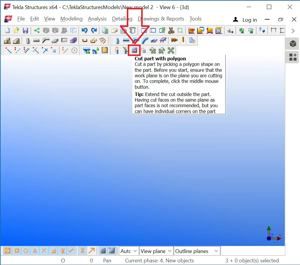
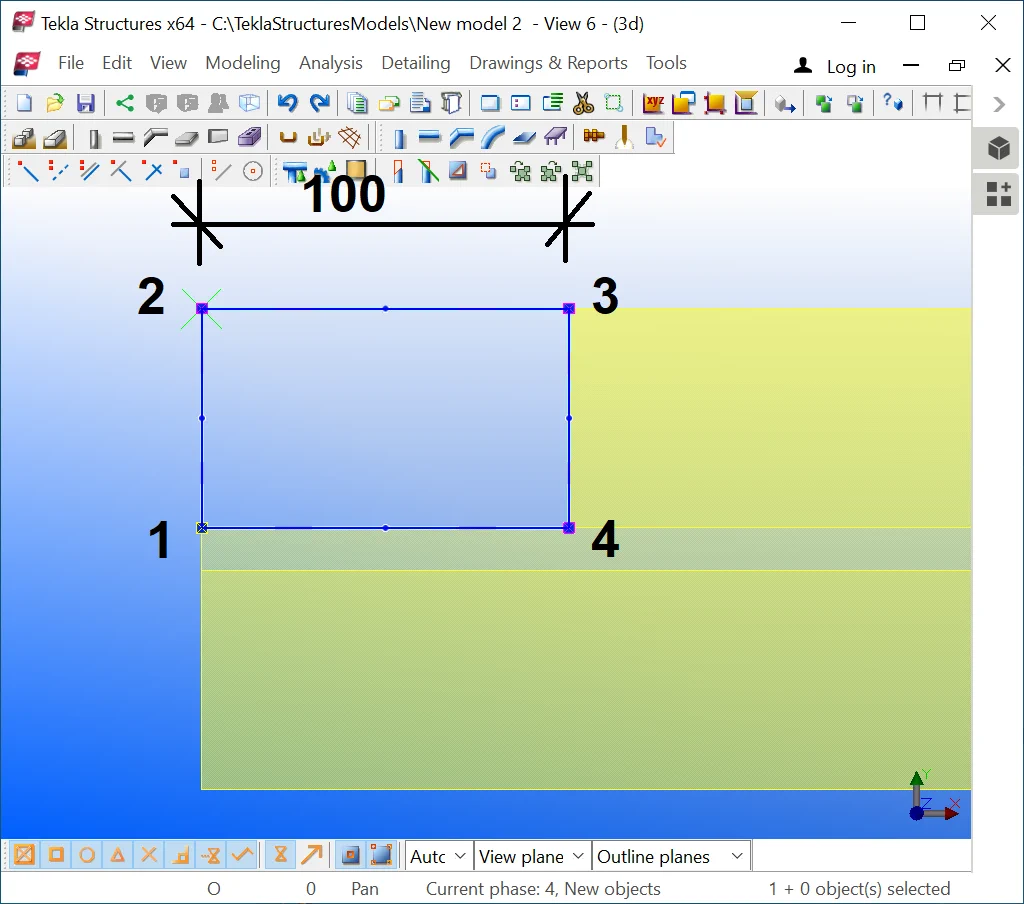
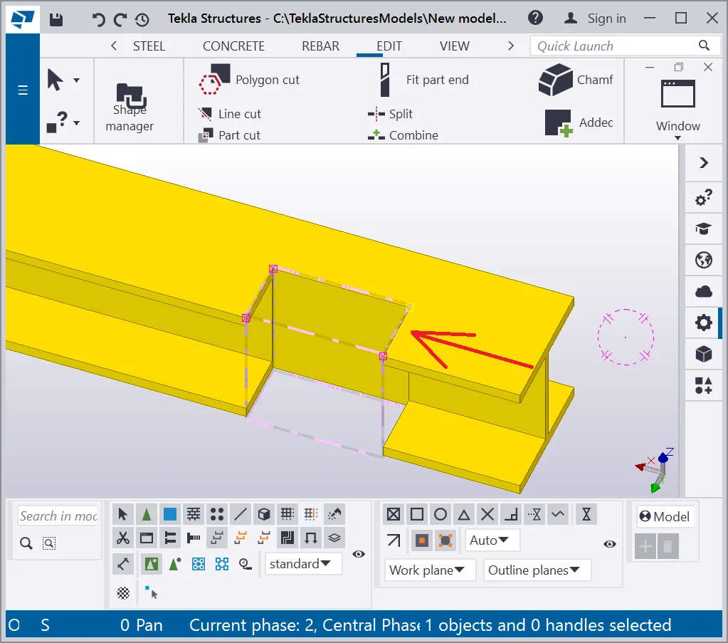
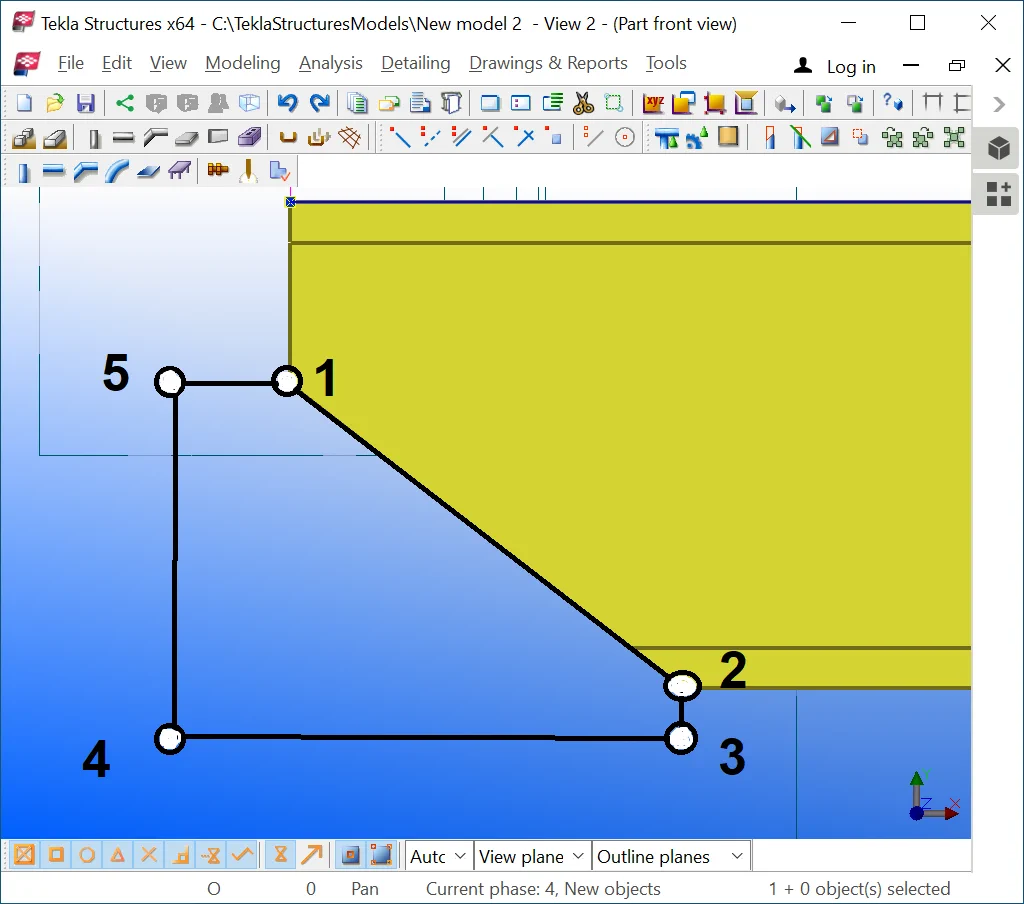
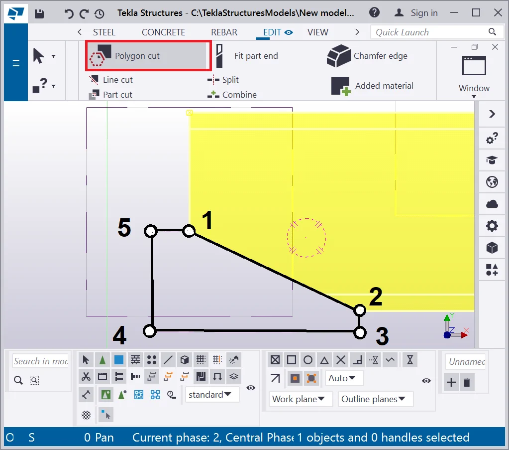
Now, let’s create an added material plate by using the following algorithm for applying the “Cut object with polygon” tool:

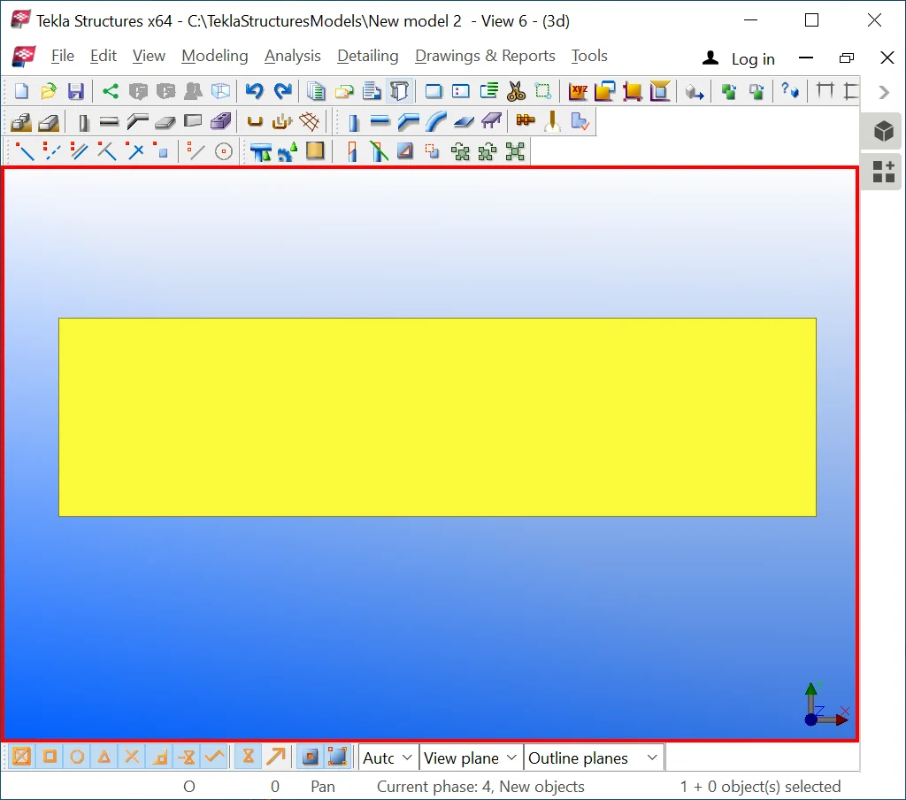
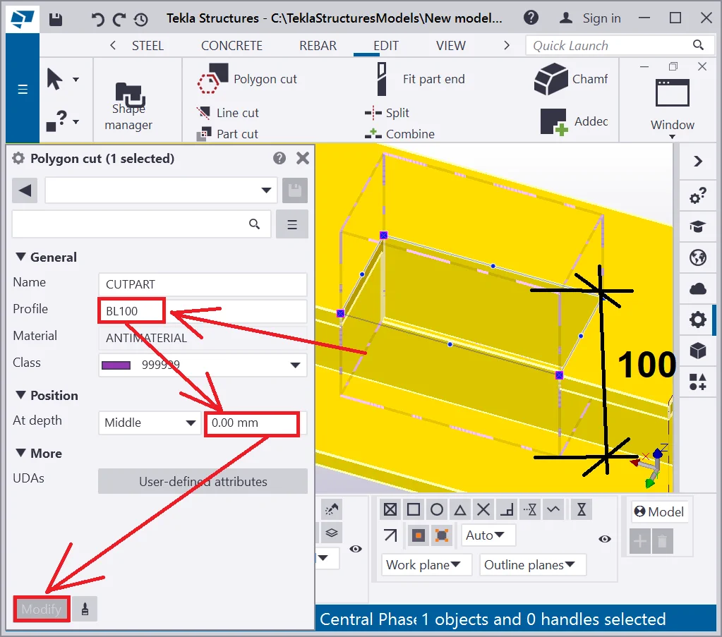
Let’s examine the new object by opening its "Properties"
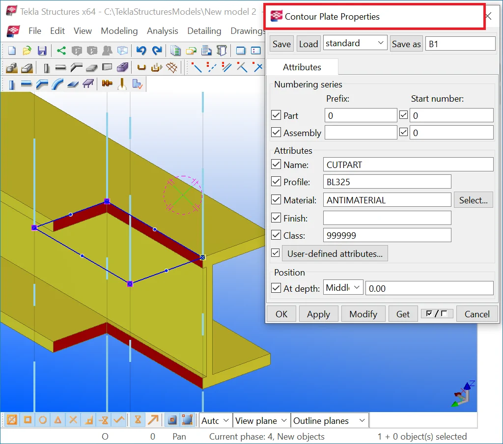

The first thing to highlight is that the "Properties" window is similar to the "Plate Properties" window, where the "Material" field value is set up as ANTIMATERIAL. But keep in mind that the “Cut object with polygon” is a separate tool, thus modifying a plate’s material to "Antimaterial" does not bring the same result.
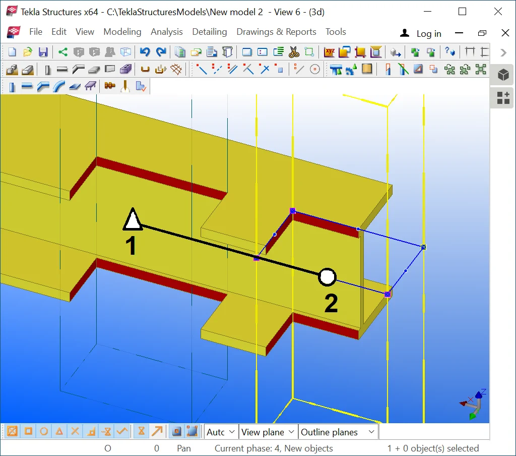
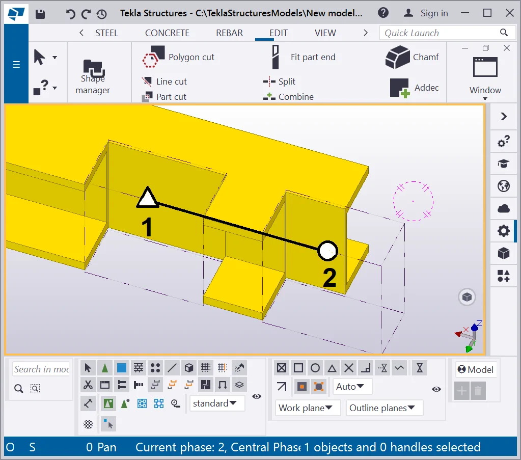
The added material plate object can be moved. Let’s move the added
Similar to the standard plate object, the added material plate can be
Proceed as shown below.
The added material plate's profile value is editable as well as its
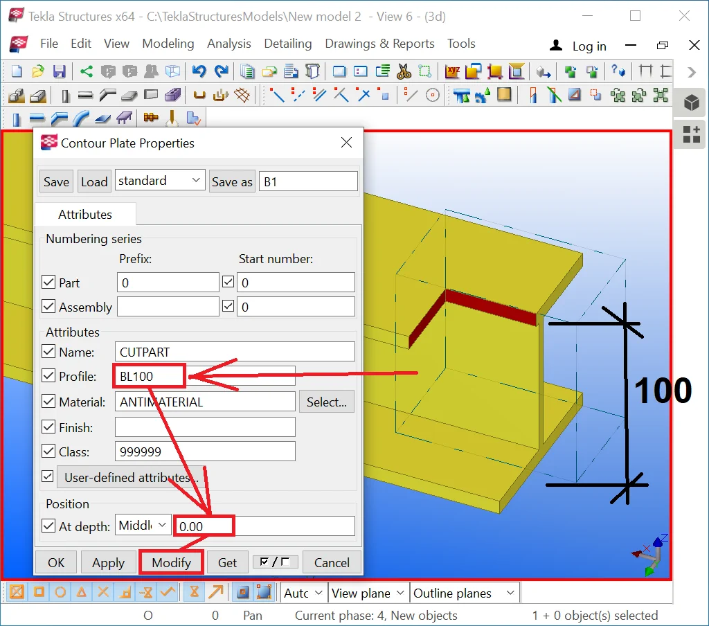
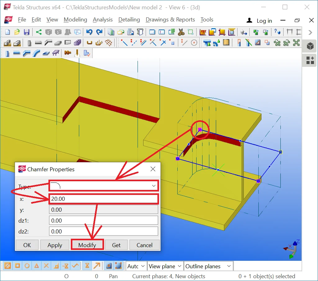
Click on the added material plate and select one of its points.
In the points properties dialog window, you can set up the chamfer type

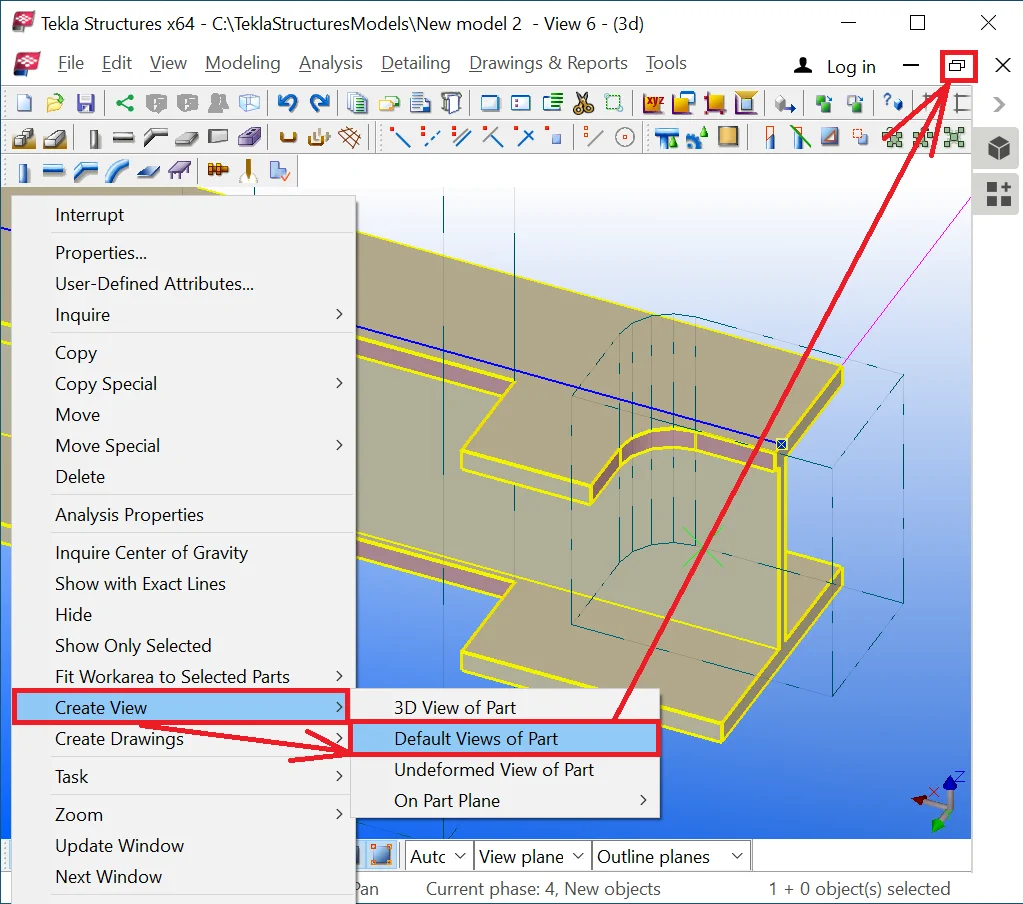
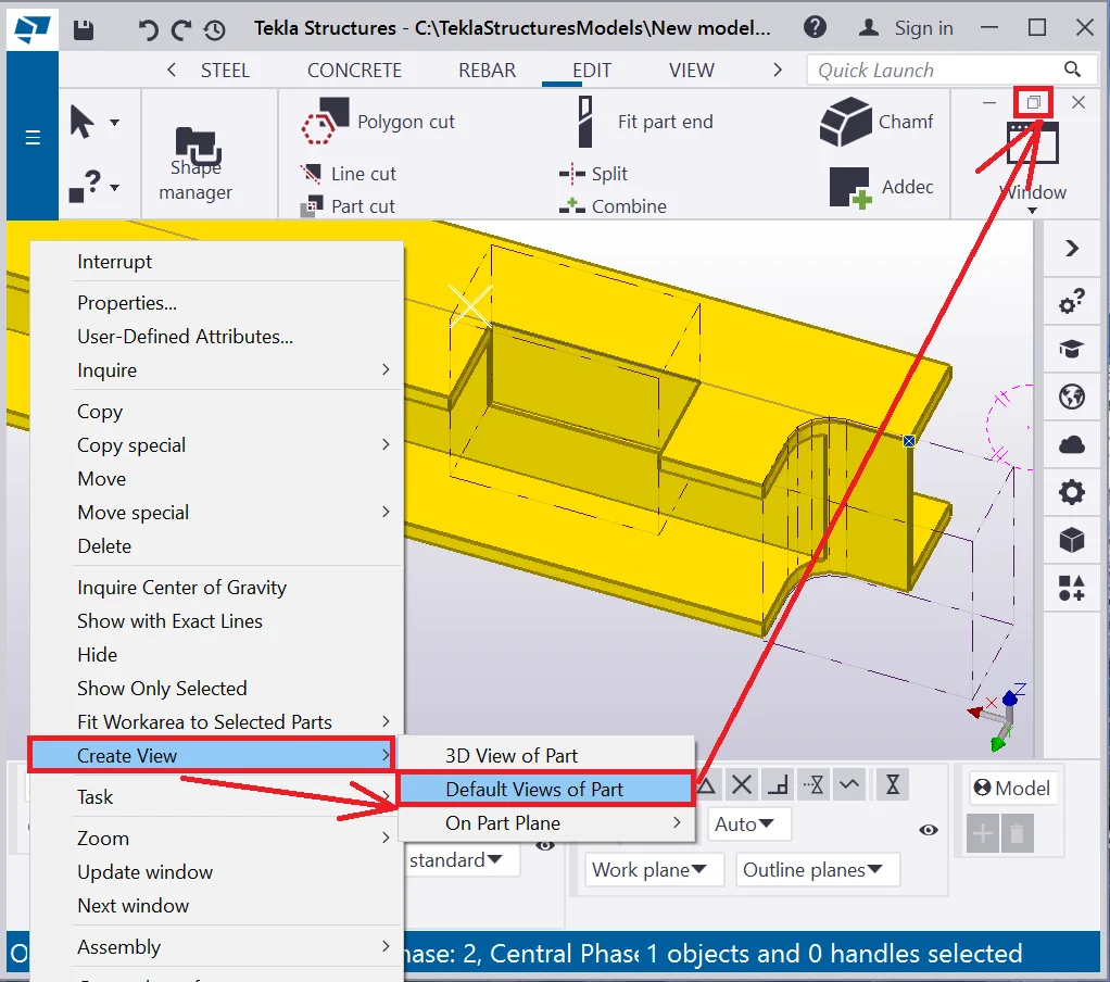
To create an added material plate at a different plane, first of all, assure all the default views of the part by using the algorithm: make a right-click on the object, and in the drop-down menu, select the tabs "Create View/ Default view of Part". Do not forget to collapse the current view to see the other view options that appeared.
Set up the work plane parallel to the view plane at the "Side view" window opened. Make sure that the Z-axis direction is perpendicular to the eye gaze direction.

Enable the “Cut object with polygon” tool.
Compare your results to the below. All the cut parts have been created
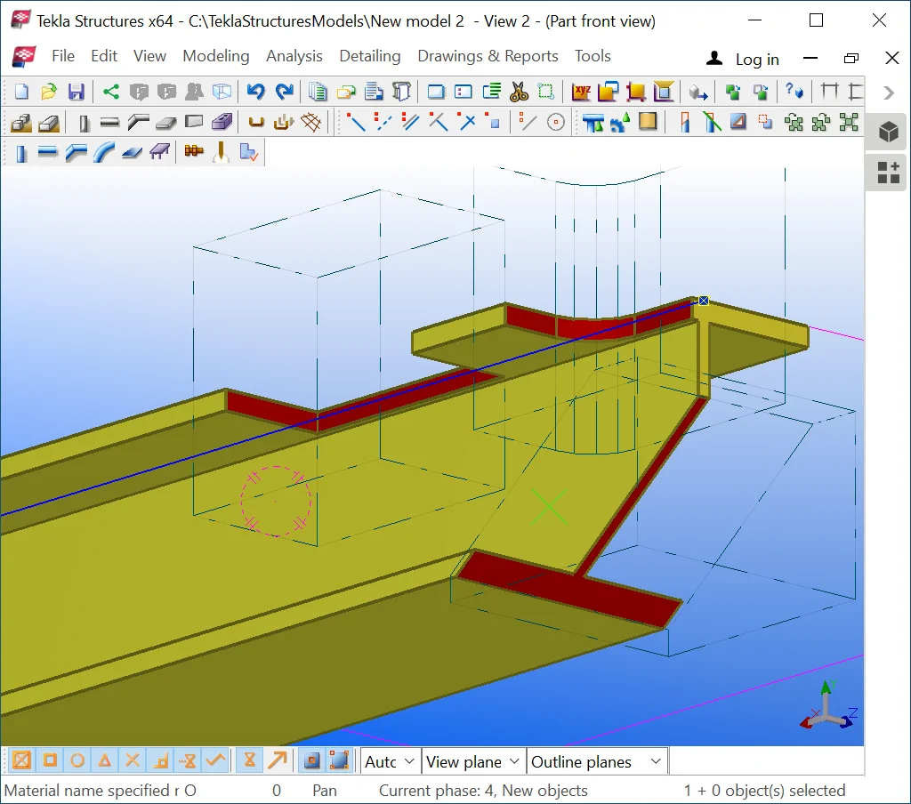

When tailoring complex cuts, the initial object might get transparent,

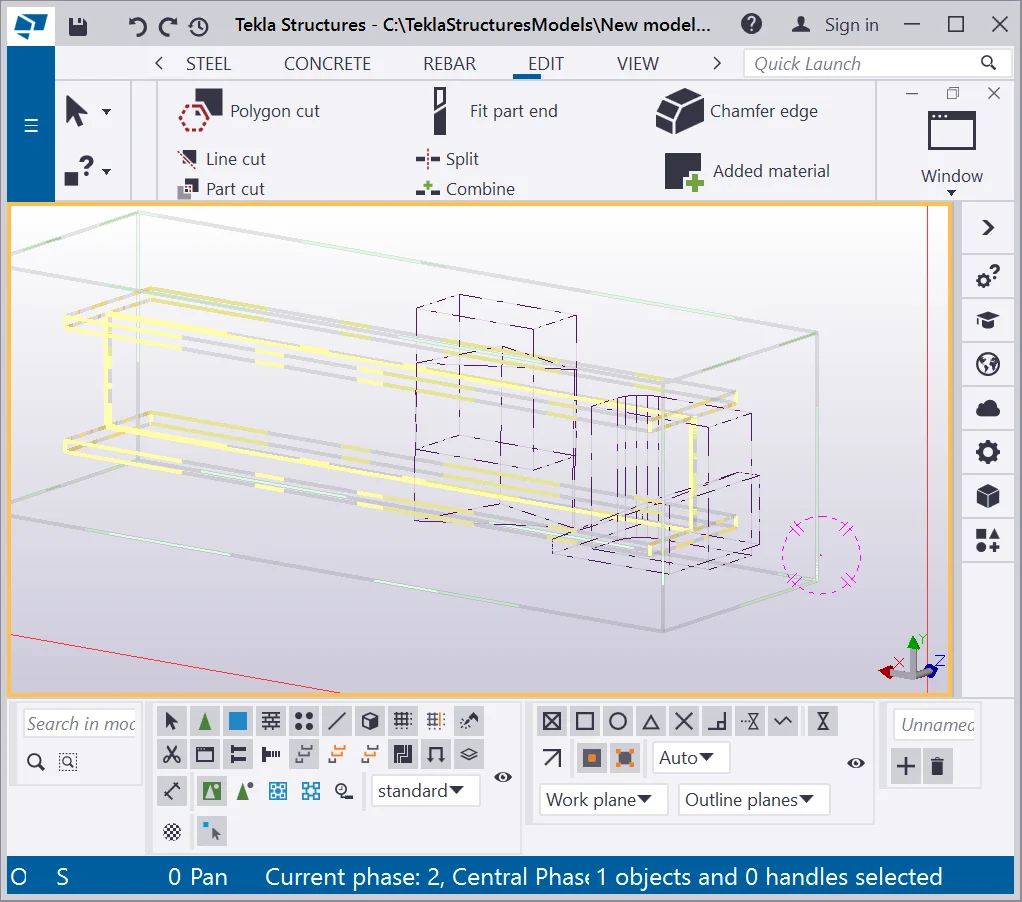
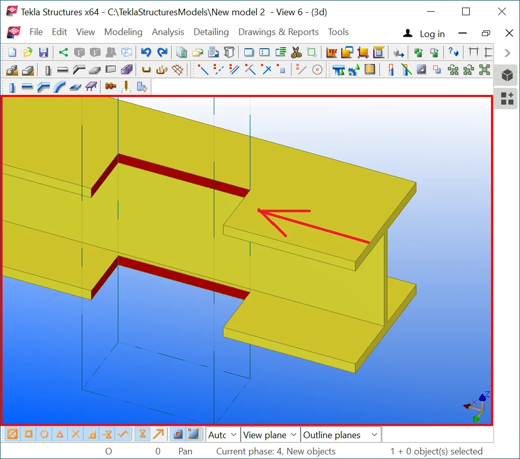
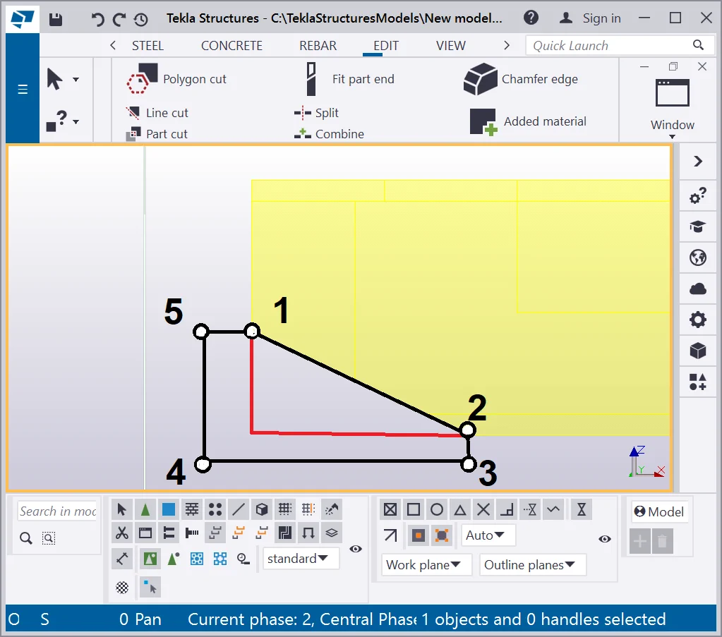
To prevent such errors, shaping out the object shall be done by paying attention to the fine duty cut not to be deleted. The errors are conditioned by partially deleting the added material plate at the object's bound
( see marked in red).
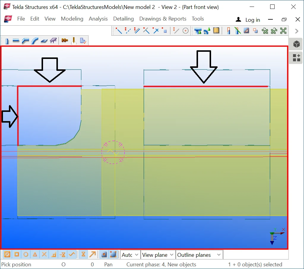
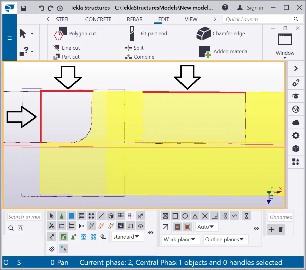
Logically it is reasonable to completely delete a part of an object without leaving the fine duty cut, but software accepts the latter as a coordinate, thus leaving the fine duty cut is quite substantial. These types of errors are particularly prevalent in complex geometry cases, such as twisted beams laid out at a perplex angle to other objects. To avoid committing such errors, we would advise shaping out the cuts in a way none of the added material parts to be coincident with the bounds of the object. Let’s modify the added material bodies created, taking into account the above. Refer to the below:


Now the added material bounds are laying out of the bounds of the object. When modeling complex projects, such over cautiousness is a key tool to avoid operational mistakes.
That is why the algorithm for creating the side cut was based on indicating
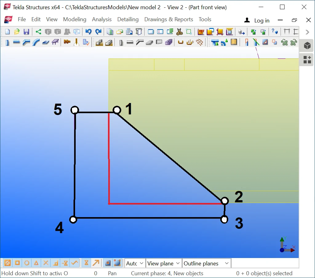
When modeling standard joints for simple beams, you can skip out on using