An orthogonal beam in its essence is a column of a constant length, but with no top and bottom points, indicating its position in the global coordinates system. Thus creating such a beam presumes indicating the points outlining its length parameter, which is constant. You can insert such a beam to any coordinates, and what is the most important perpendicularly to the view plane.
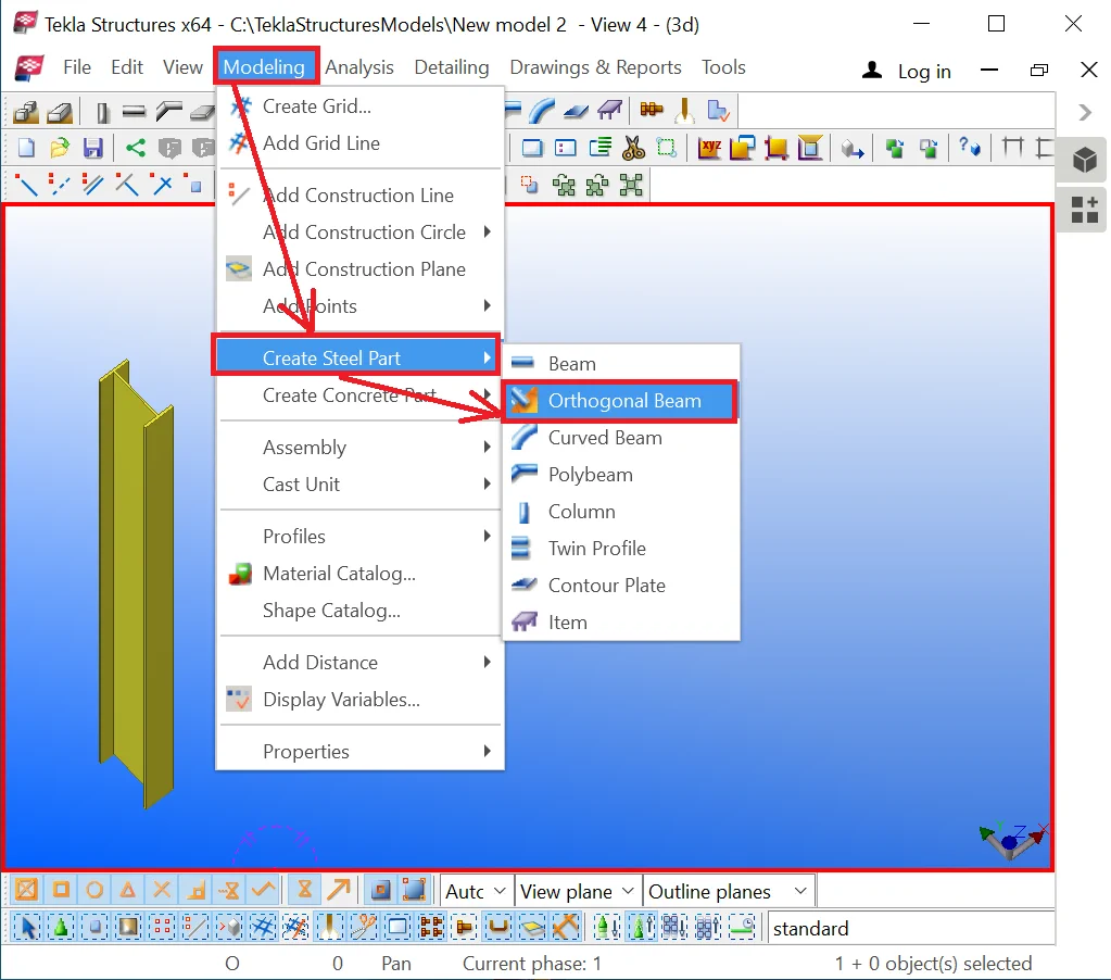
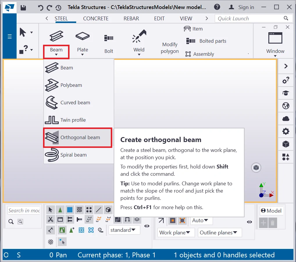
Try out creating an orthogonal beam to understand its functioning. Open
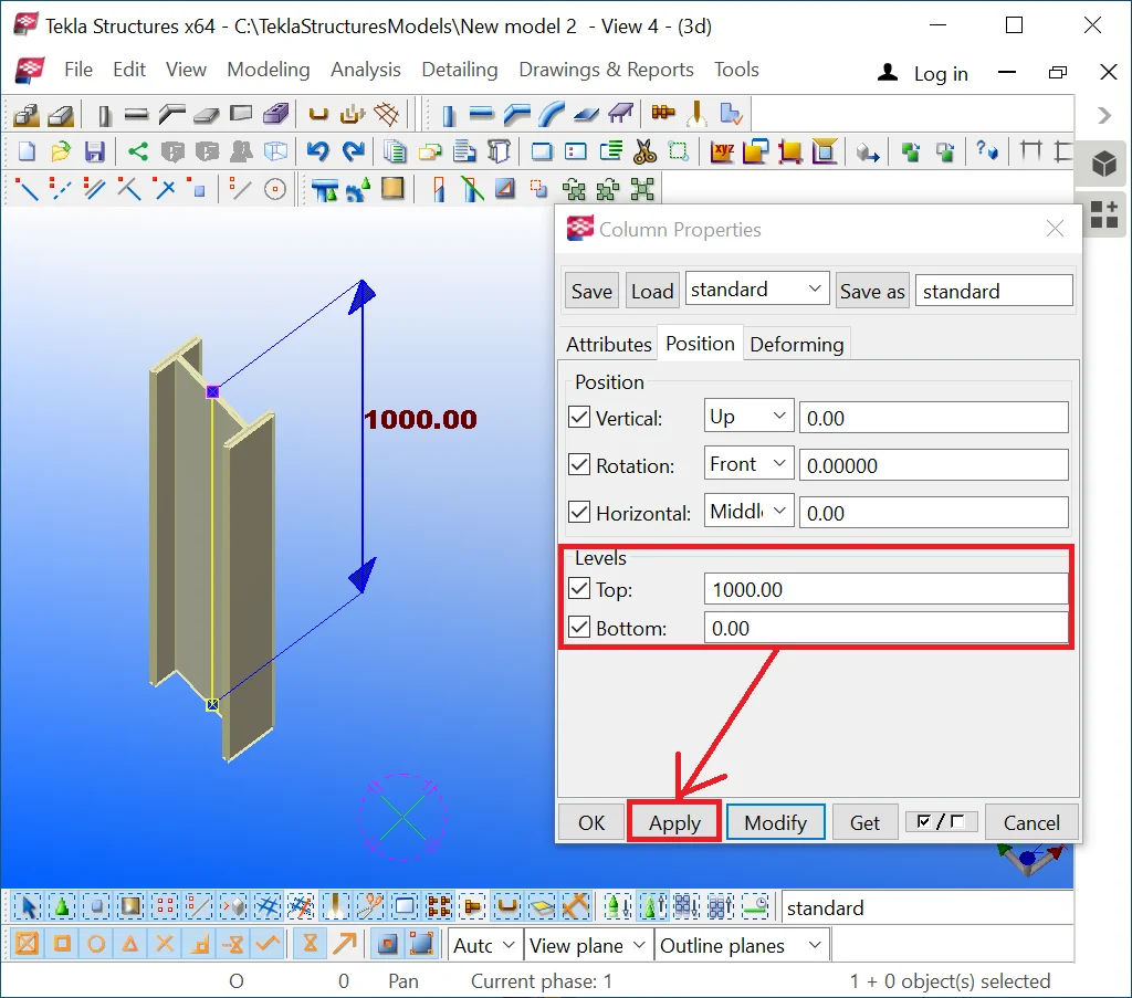
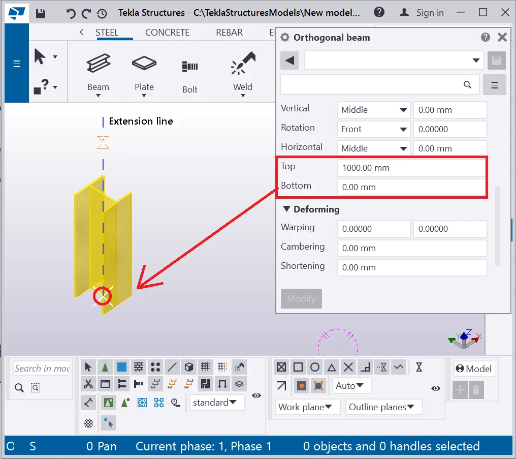
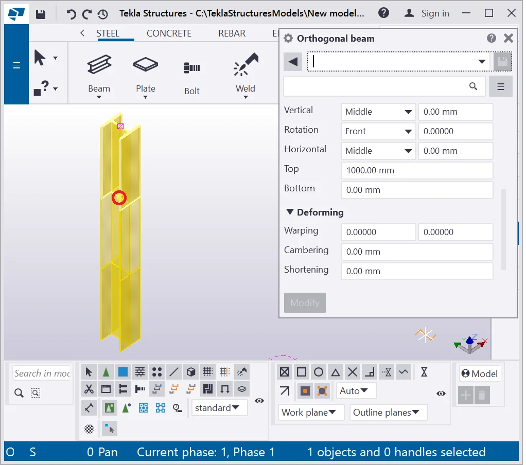
Set up the values of the “Levels” section parameters in a random way, but keep in mind that they stand for calculating the object length only. Thus, if you need a beam of 1000mm length, then the top and the bottom points values should be respectively 0 and 1000. Let’s modify the orthogonal beam to the 1000mm length and set up this value as a default one for the consecutively created objects of this type.
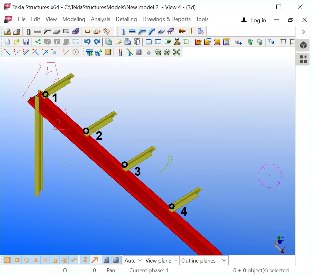
Enable the “Orthogonal beam” tool and create a new beam above the one already created. Despite the standard column object, the orthogonal beam gets inserted by a left-click at the required coordinates, and none of the “Levels” section parameters are to be modified.

Repeat the above and create the third orthogonal beam object.
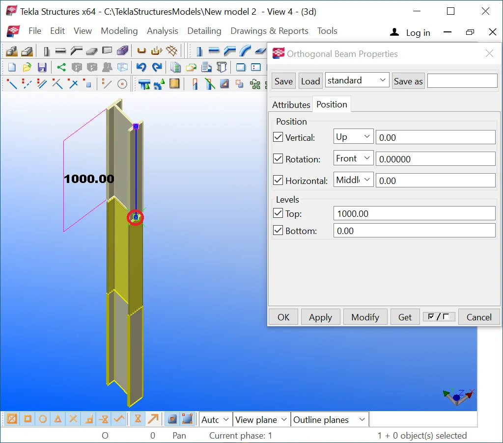
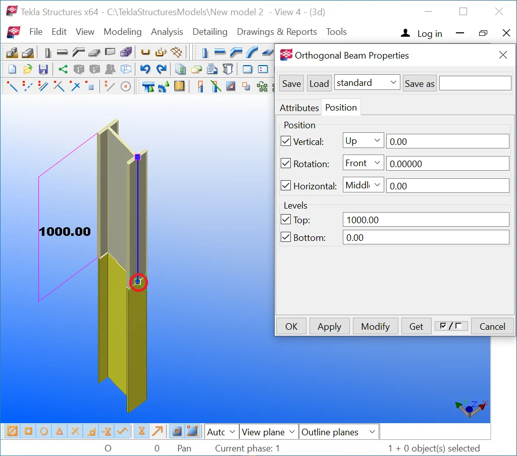
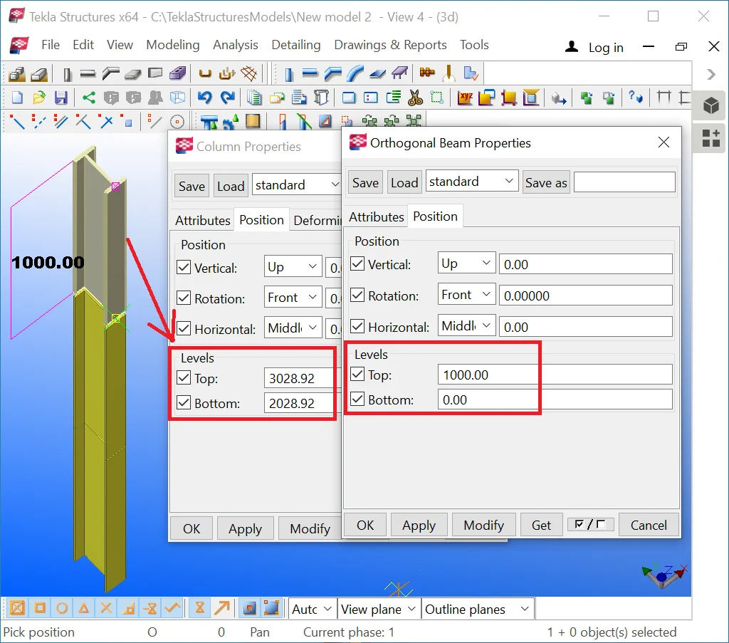
Double-click at the object created opens the “Column Properties” window indicating the coordinates of the object in the global system of coordinates.
Thus, we can conclude that the “Orthogonal beam “ tool does not create an object of a new type, it just allows creating columns by introducing their coordinates differently.

The above example allowed us to understand how to set up a constant length
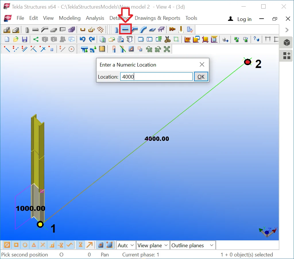
Create one more simple beam of 4000mm length as it is shown below:

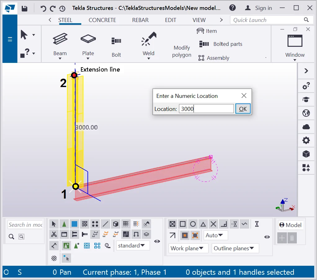
Select the new beam object and move its starting point orthogonally upwards. Refer to the below:

Now let’s examine the very scope of the “Orthogonal beam” tool. As we know, it allows creating a beam of a constant length perpendicularly to the view plane or a work plane.
Let’s set the work plane by enabling the “Work plane tool”

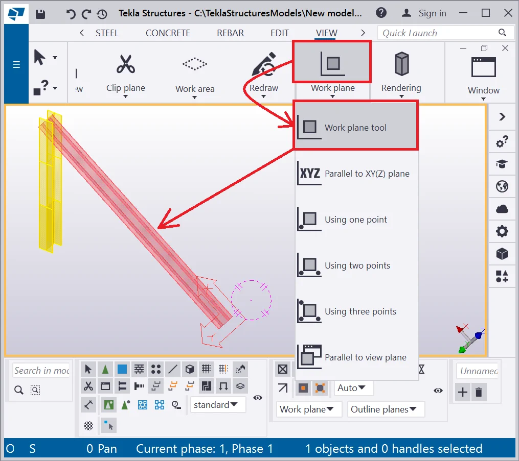
Note that the new reference plane axis icon had appeared along with the
Enable the “Orthogonal beam” tool and randomly create several beams at the inclined object. All the new beams will be of the same length and located perpendicularly to the referent work plane.
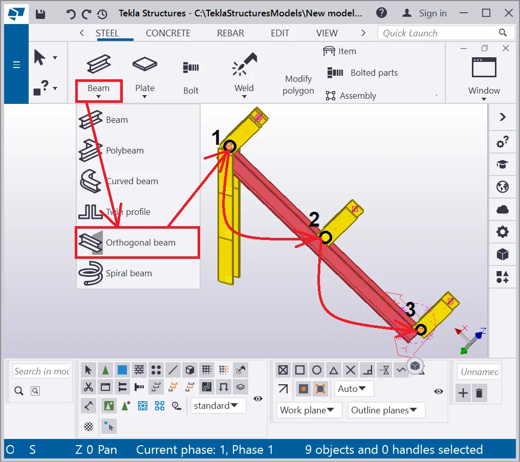
Thus you can see that the main scope of using this tool is modelling complex
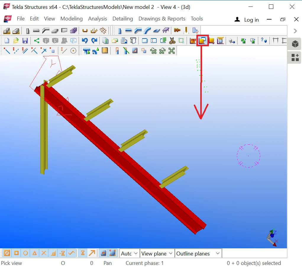
Restore the work plane by selecting the “Parallel to view plane” tool and executing a left-click on the view. If you carried out all the steps correctly then the Z-axis is perpendicular to the eye gaze direction.

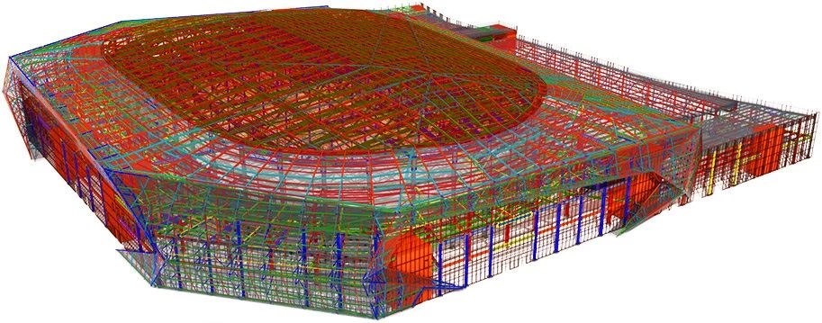
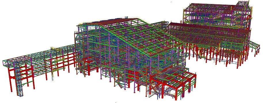
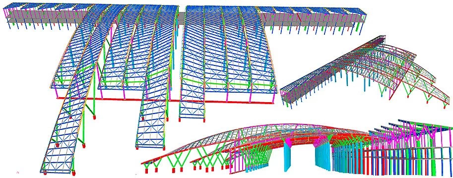
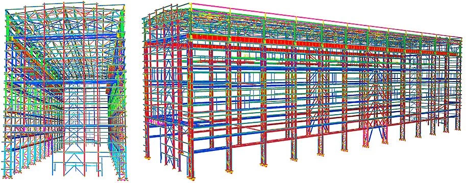
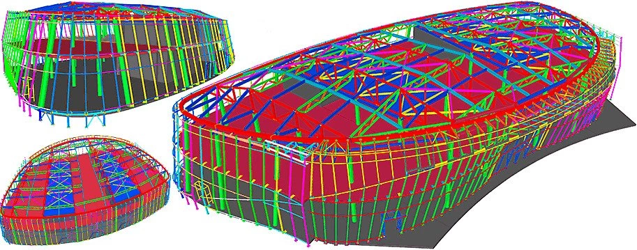
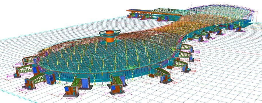
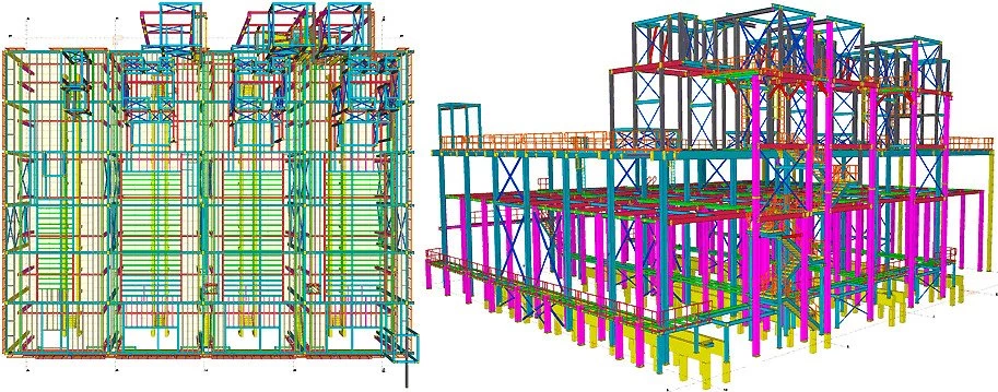
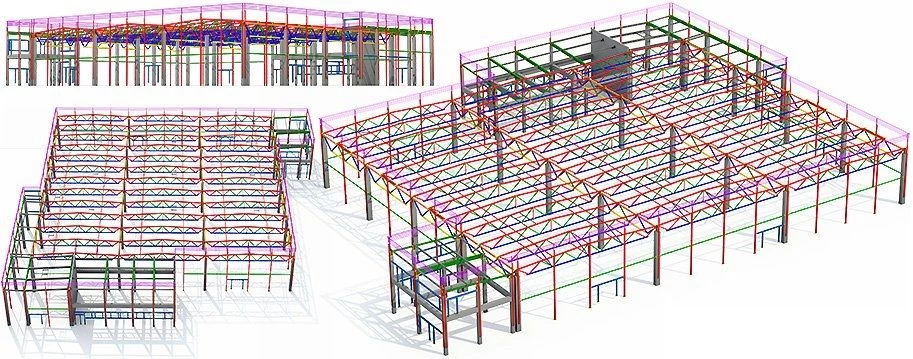
Below you can see the example of a structure determined by a large number of elements perpendicular to various planes, which are face panels and their brace systems of an airport structure. The below picture is a fragment of the communication building of a complex drop shape.
Since such structures are extremely complex in shape, each panel is located at a complex spatial curve and each panel is of different size with its bracings being strictly perpendicular to it. Drawing up such a structure is done by using the “Orthogonal beam” tool.