The algorithm for modeling a welded non-uniform cross-section beam in
TS differs from the respective for welded uniform cross-section beam by
not taking into account the reference line of the profile.
The reason is that non-uniform beams are of seldom use and their slope angle in the majority of cases coincides with the respective angle of the roofing and walls. That is why there is no need to rotate (slope) them, but it will be more convenient to modify them with the above reference line position.
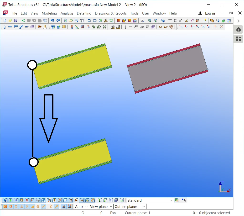
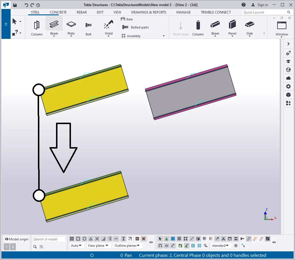
Copy the beam from the previous exercise downwards at 1300 mm.
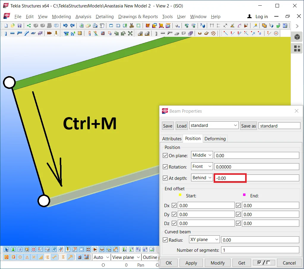
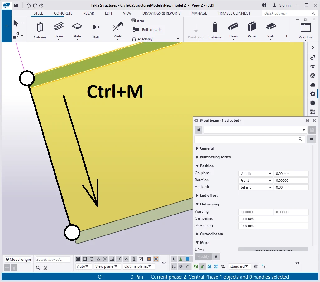
Select the beam wall and set out its “At depth” value according
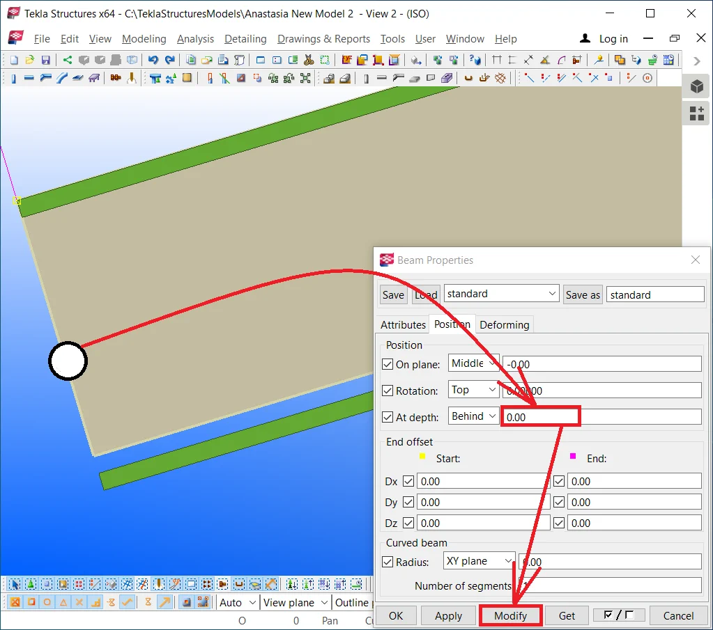
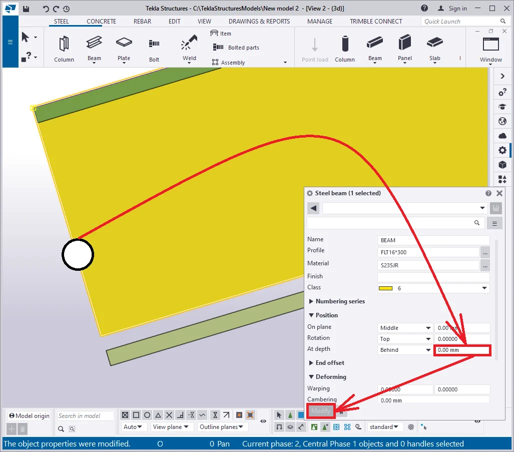
Move the beam's wall downwards in the way its flange gets laid at
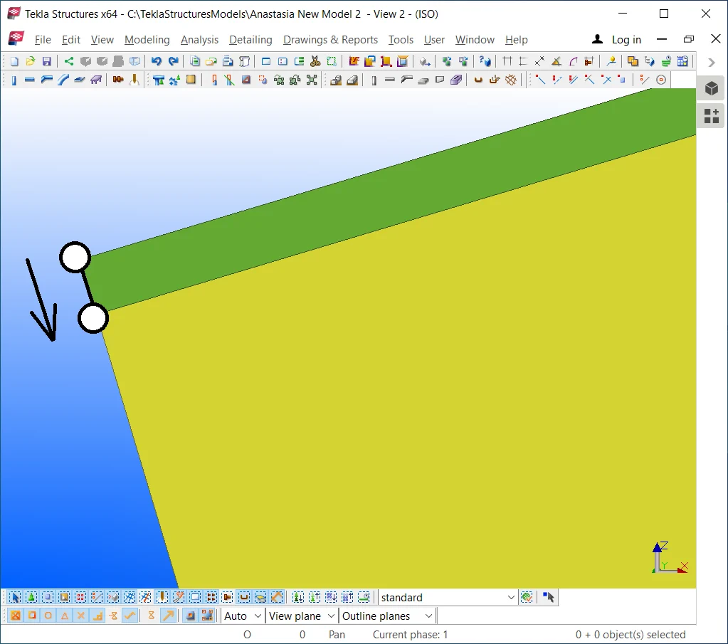
Proceed to set to null the bottom beam's flange offset value. Thus
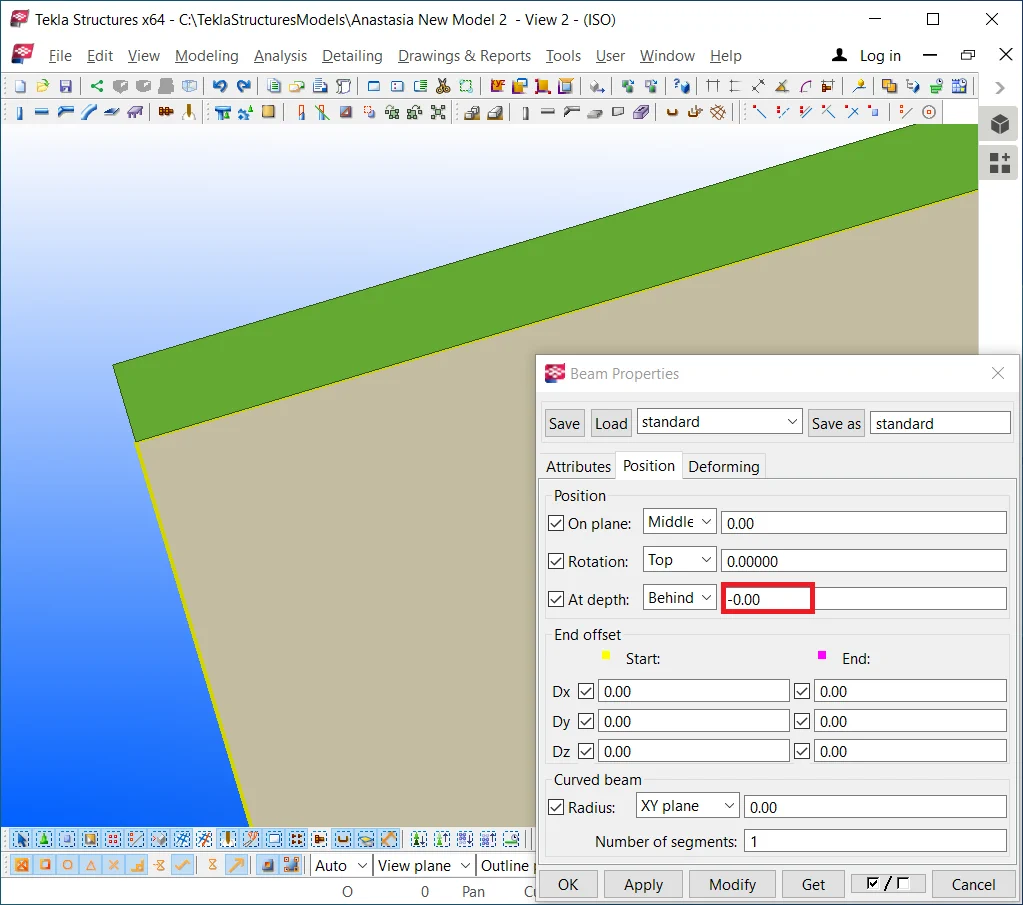

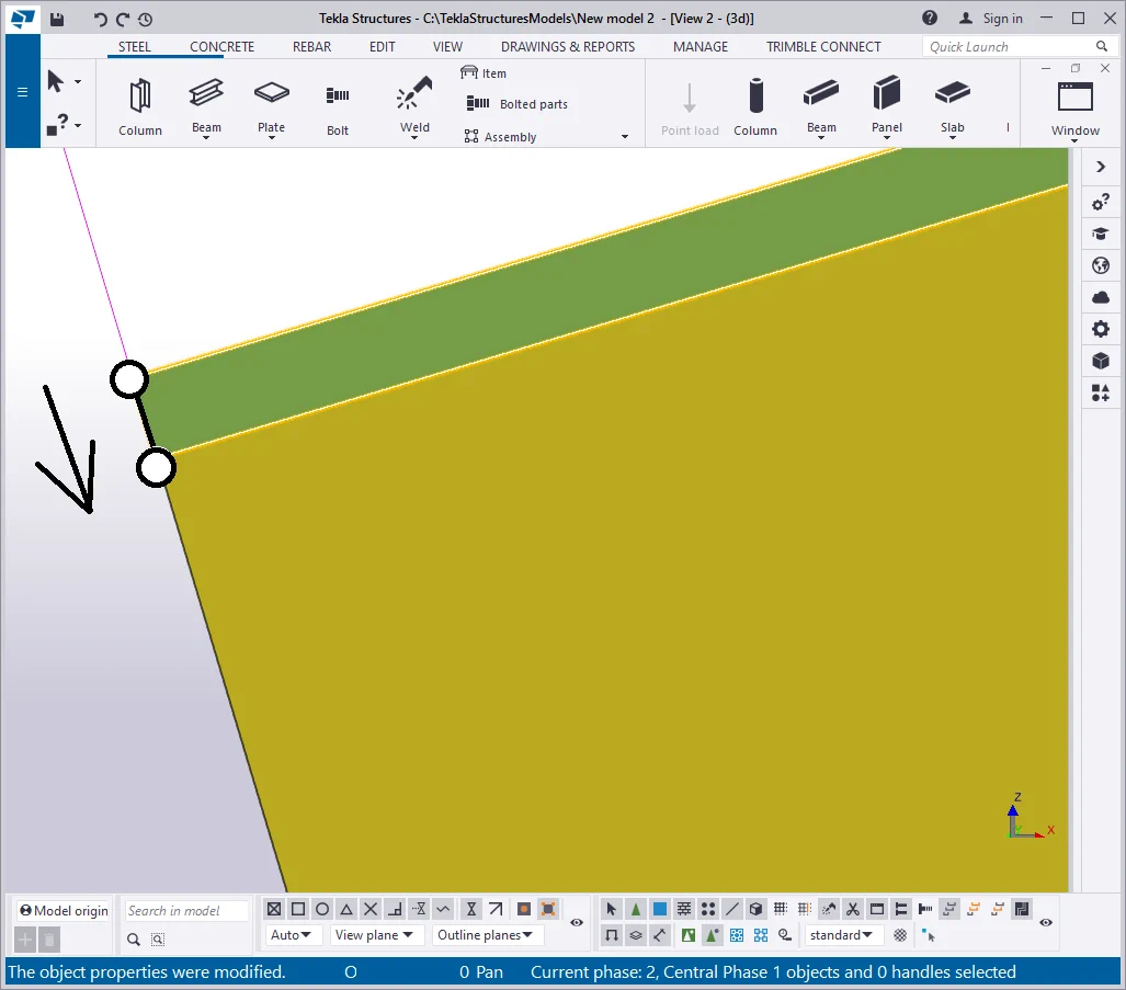
Move the bottom flange to the required position without recurring to setting
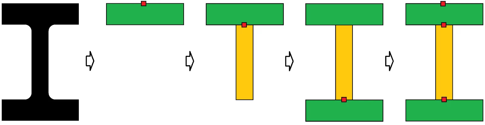
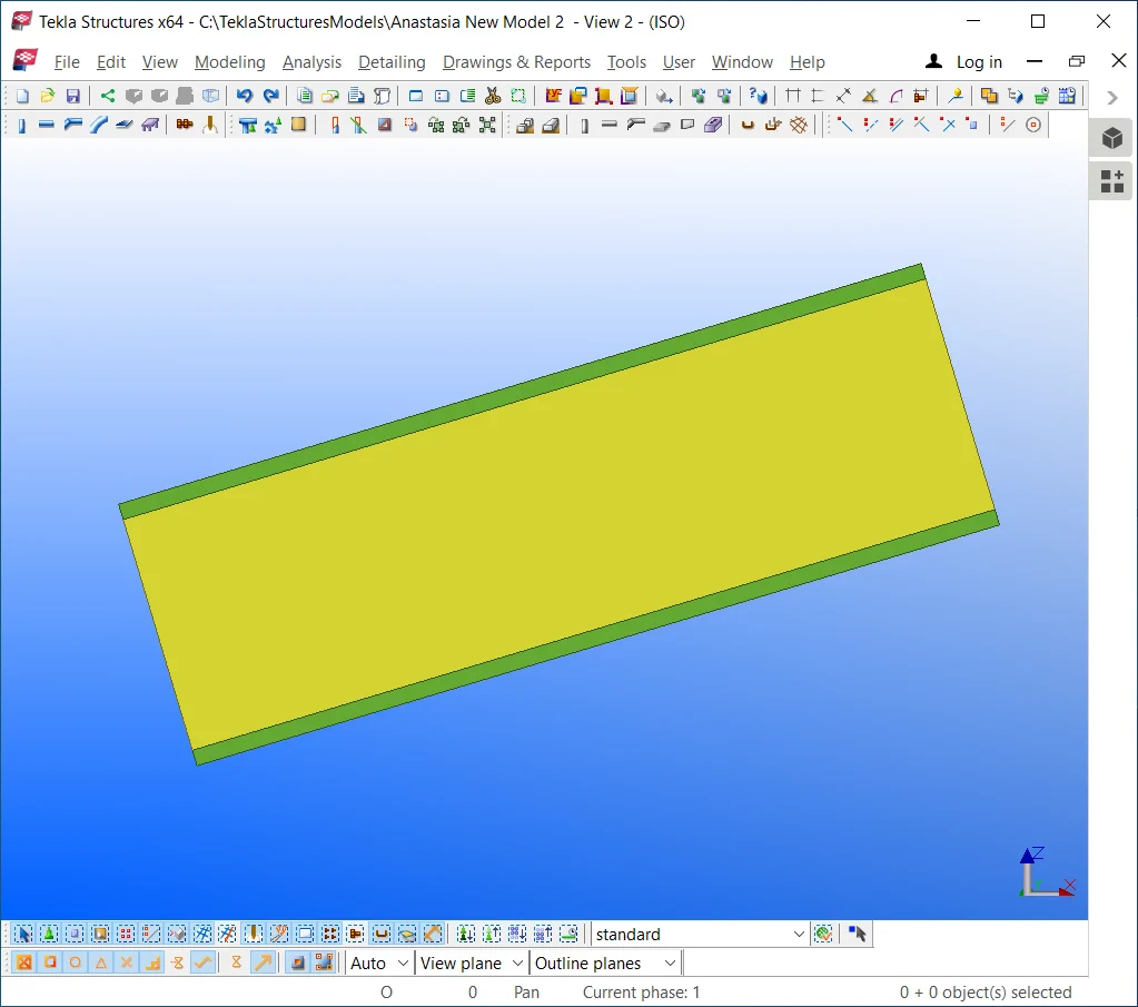
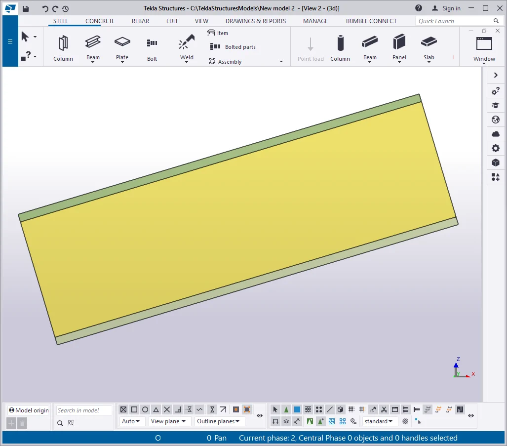
Thus we have created a uniform cross-section beam with different reference
Maximize the height value of the beam's wall at 200 mm by changing its profile to “—20*500”. Modify the beam's wall class value to 13 for a better visual distinction.
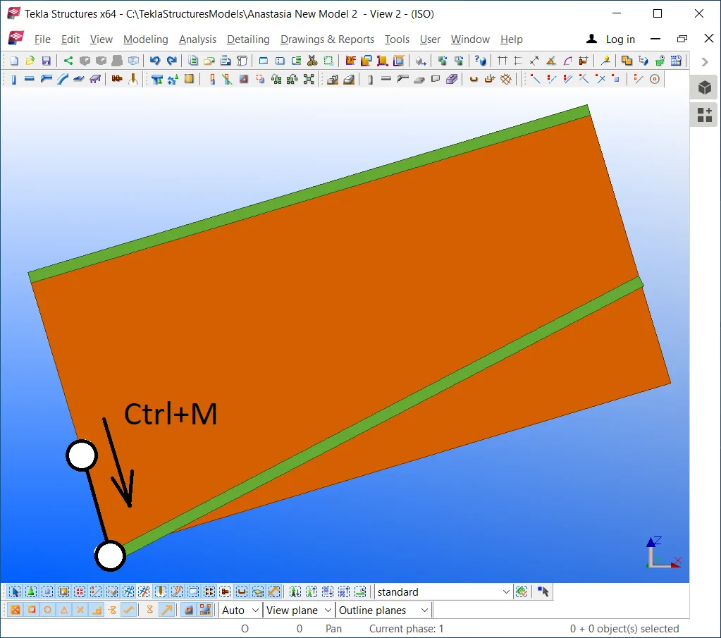
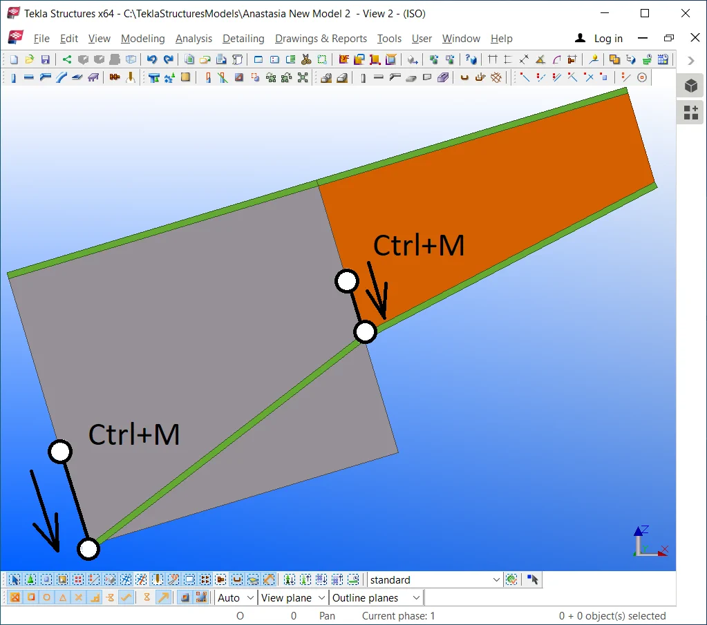
Click on the bottom flange and select its left point. Move the point as

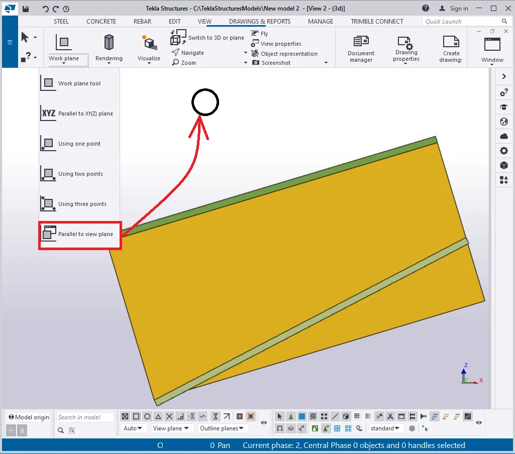
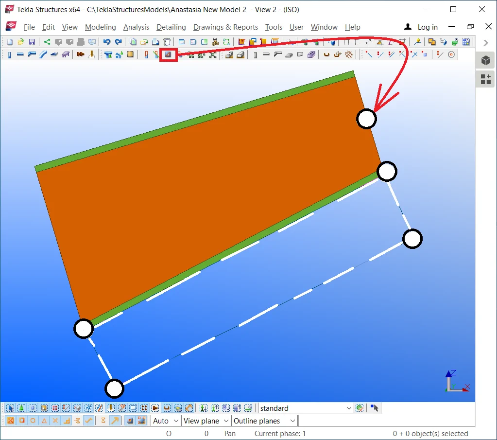
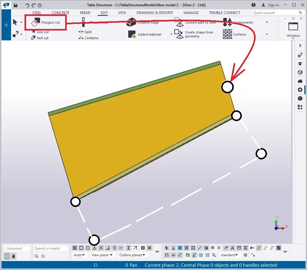
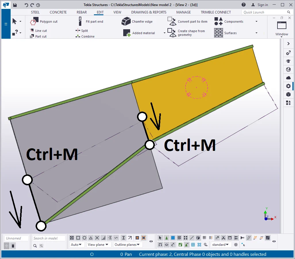
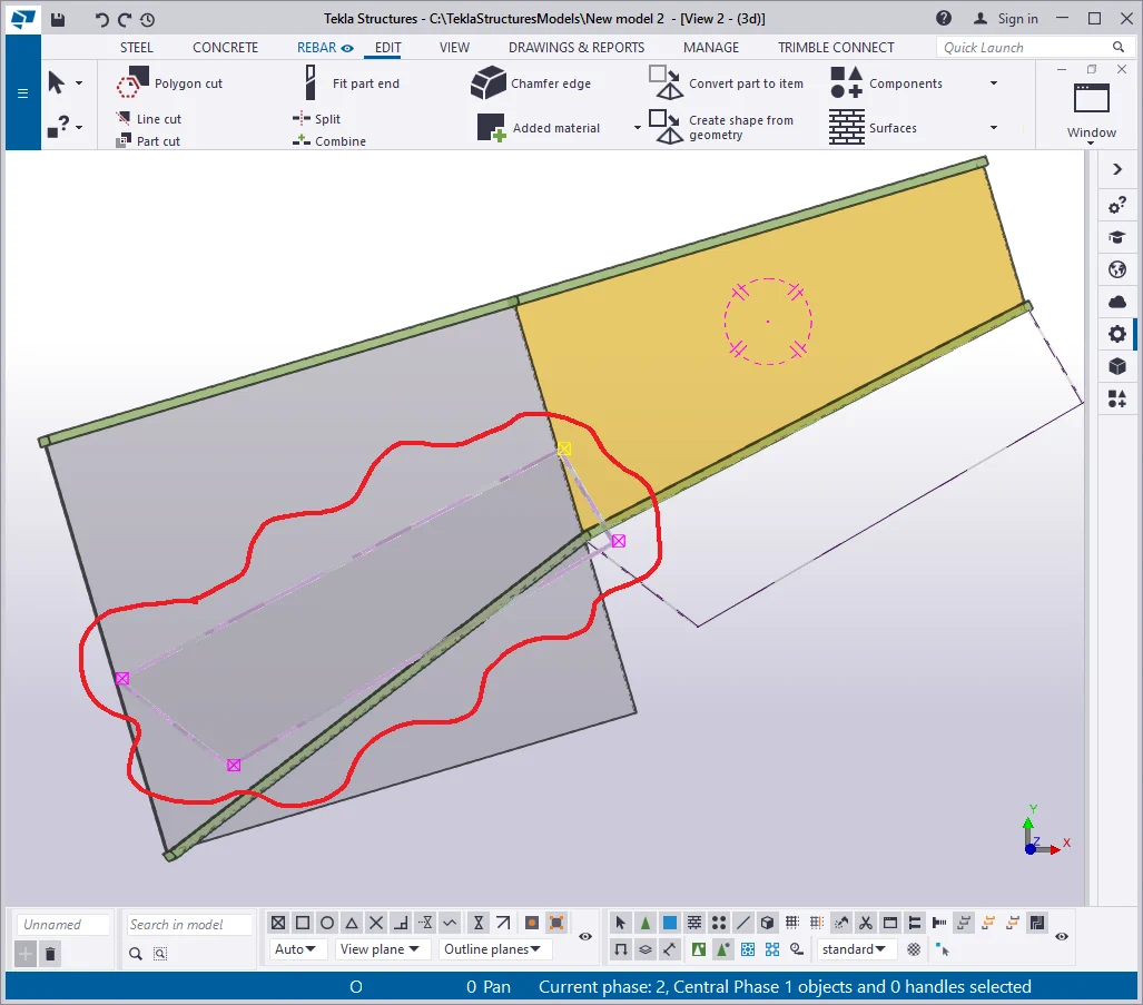
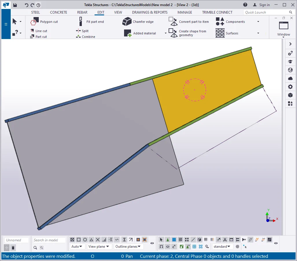
Execute the polygon cut. Prior to this, make sure that the Z-axis is perpendicular
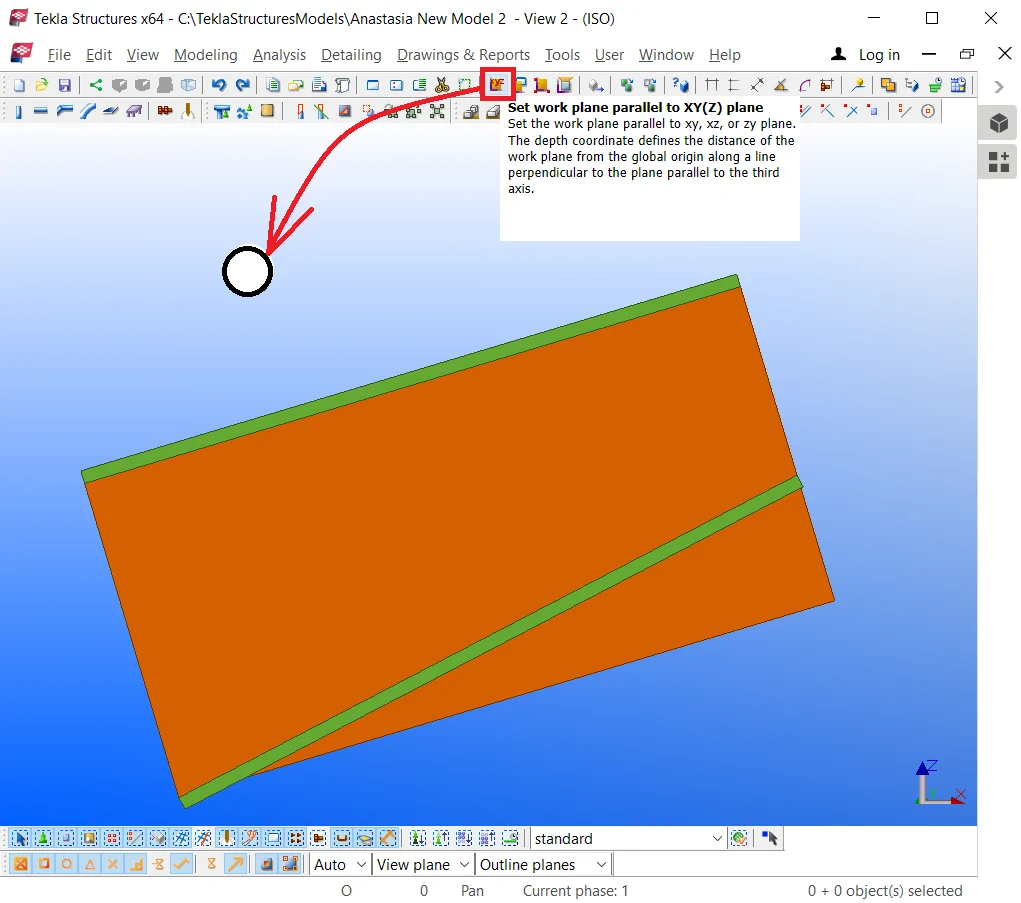
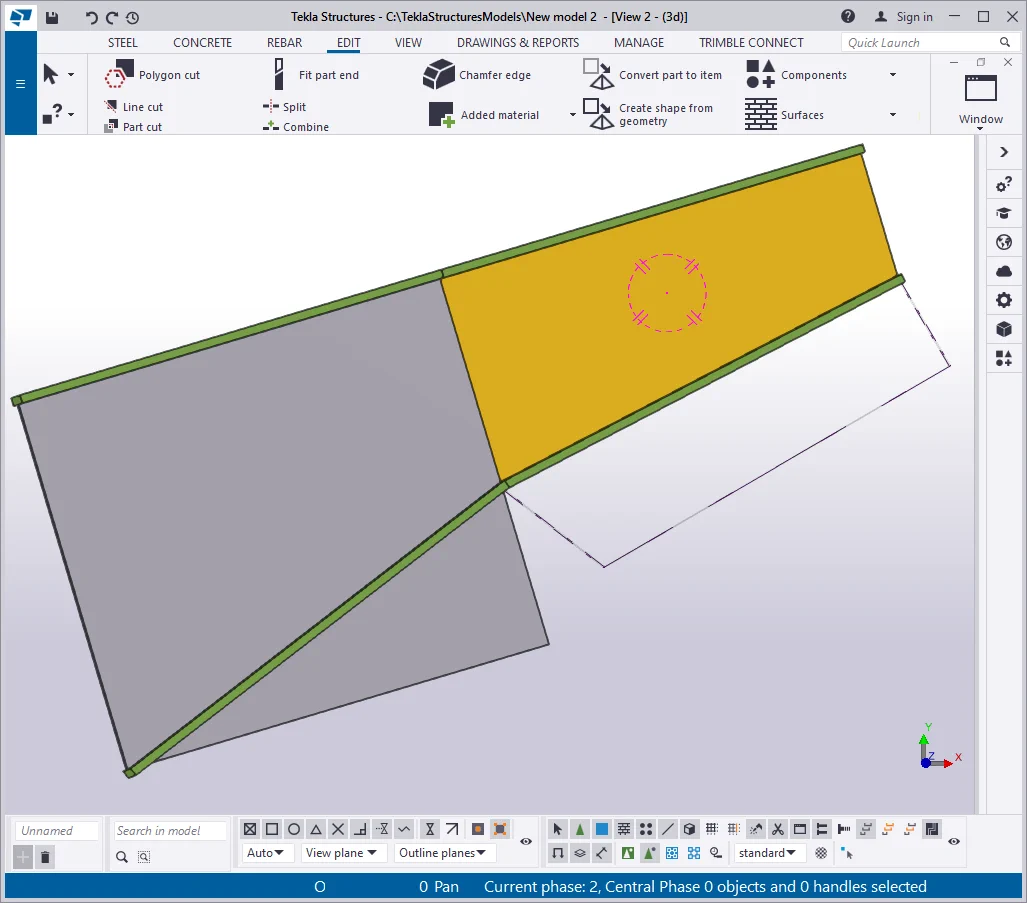
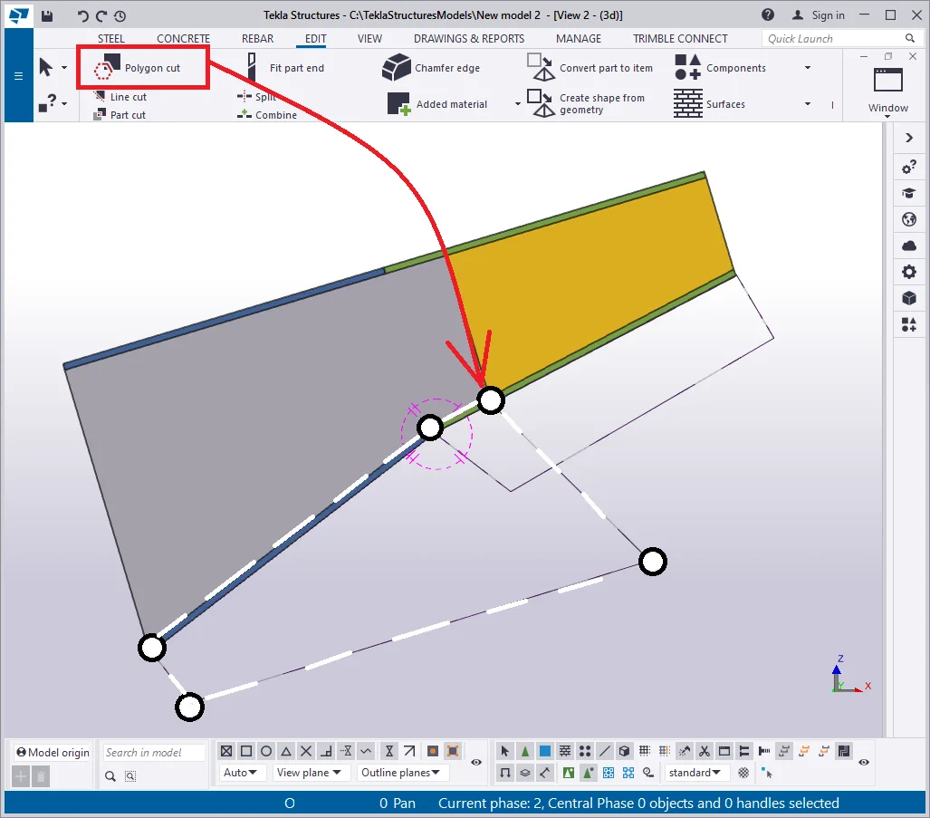
Execute the “Polygon cut” in the way the resulting added material
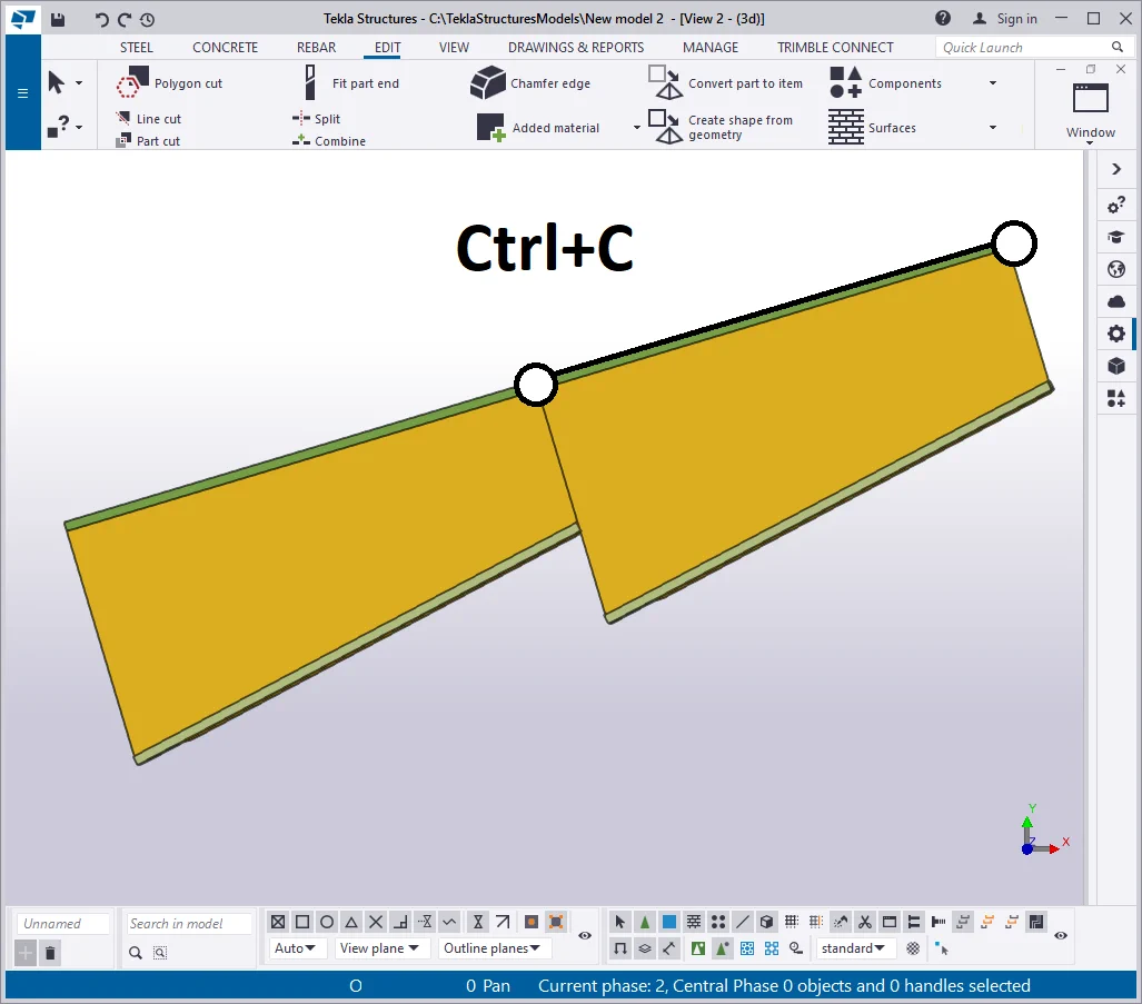
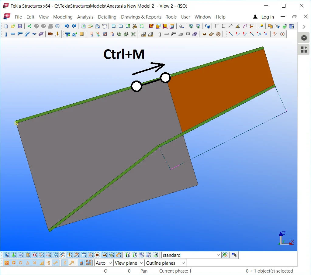
Copy/Paste the beam to the left by using the Ctrl+C hotkey combination.

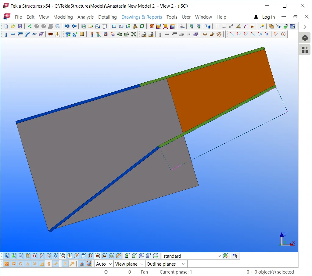
Modify the profile of the copied beam's wall to “—30*900”.

Move the bottom flange points as it is shown below:
Note that the added material object does not work anymore, as its initial
Go to the added material properties window and configure its thickness
Delete the added material plate and create a new one.

To avoid allocating in a line the welded seams of the beam flanges and

Modify the width parameter of the right beam flange at “—20*250”,
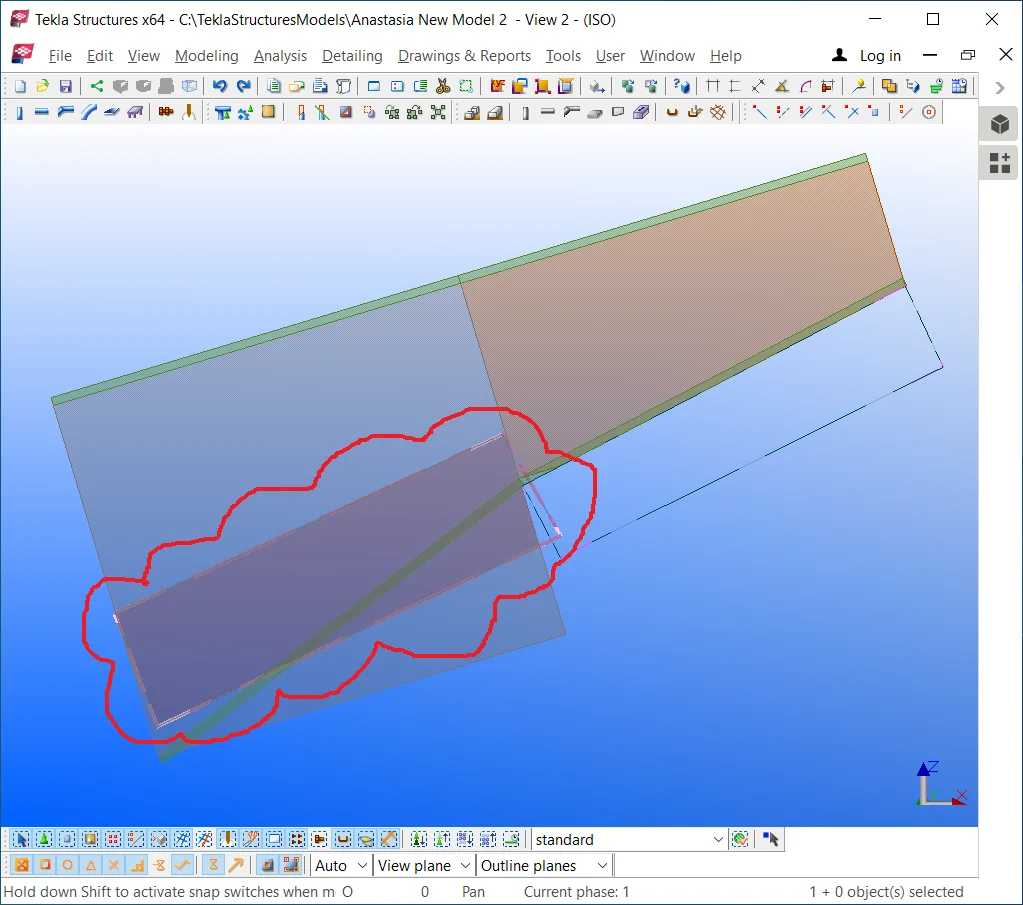
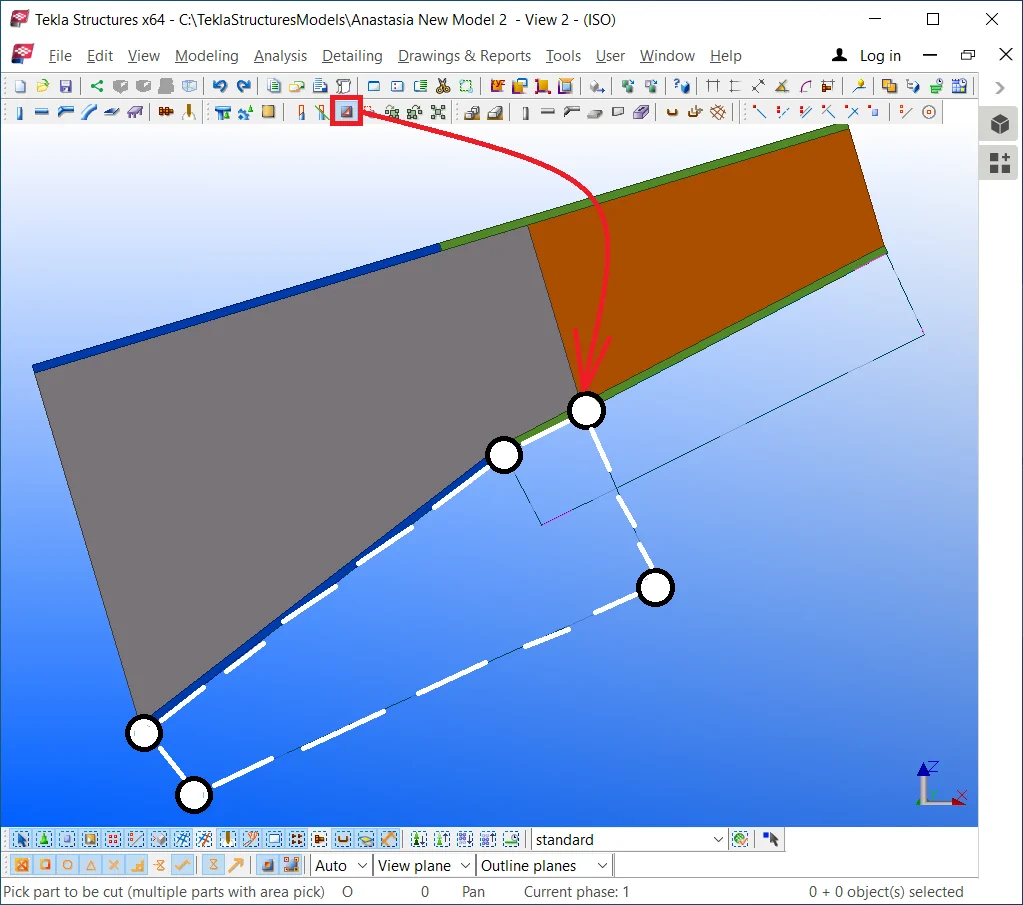
Create a polygon cut, where 3 points are located at the outer face bottom
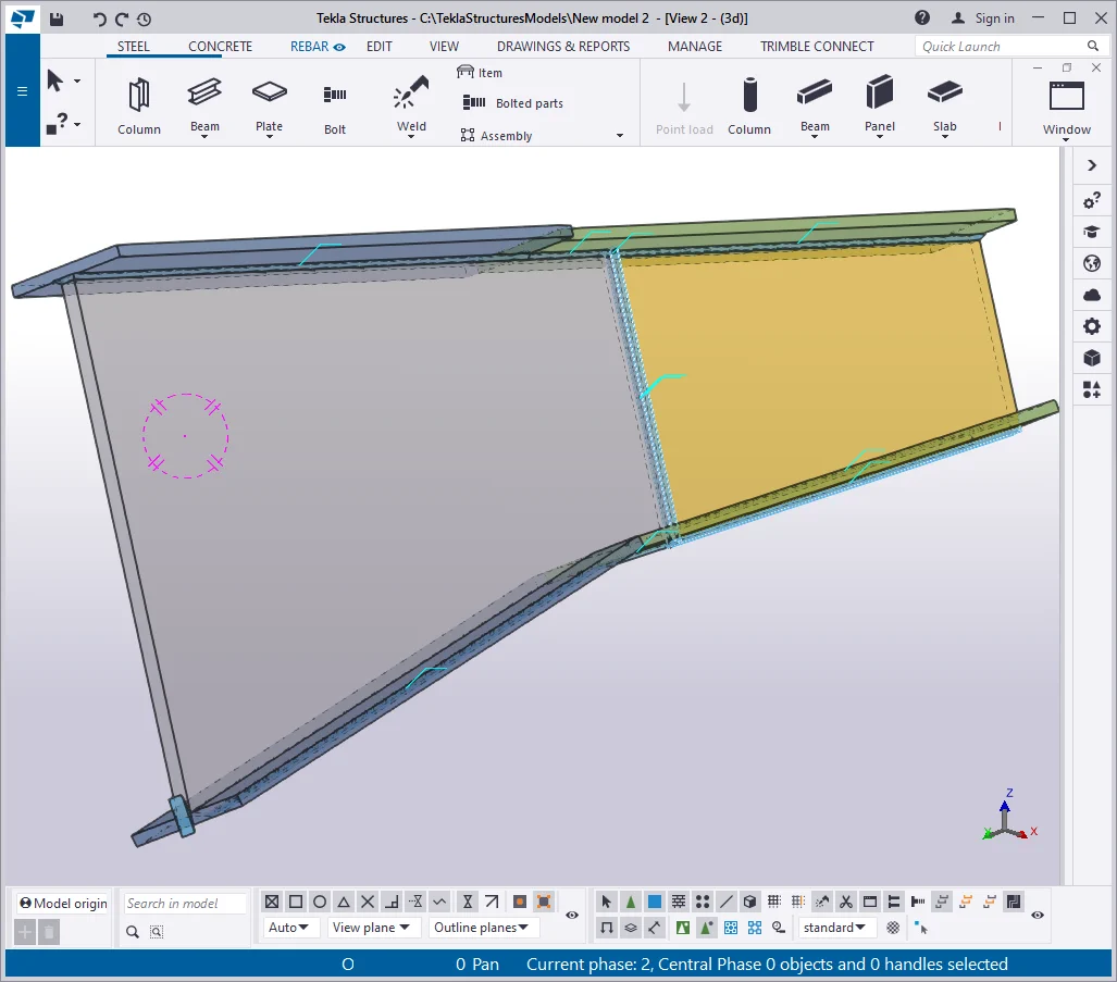
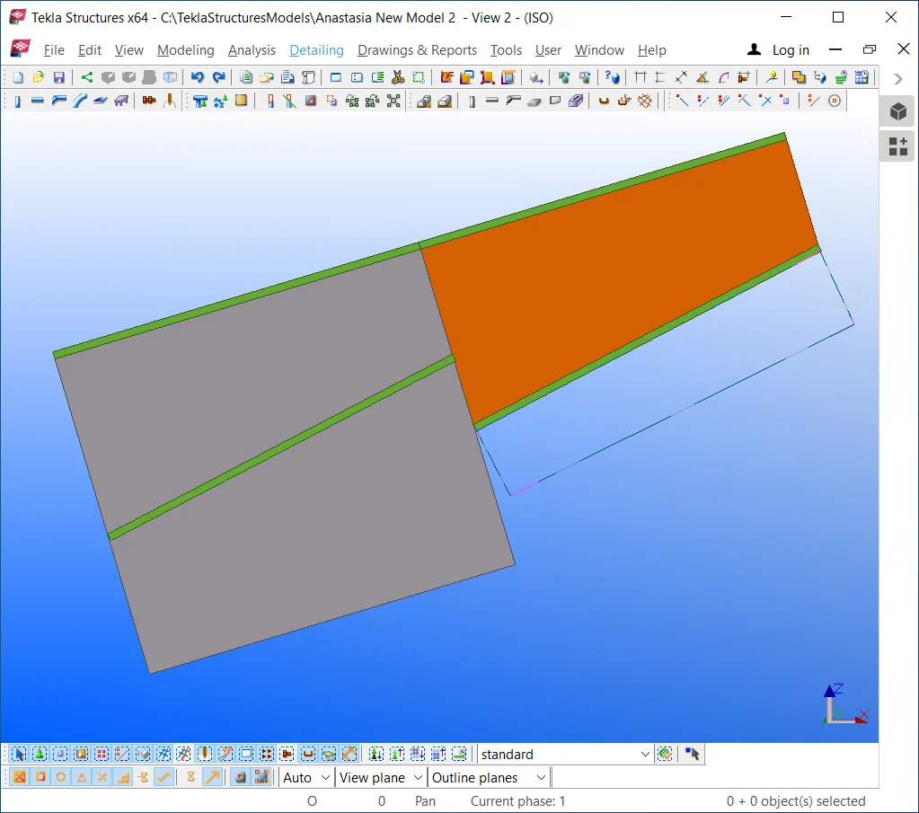
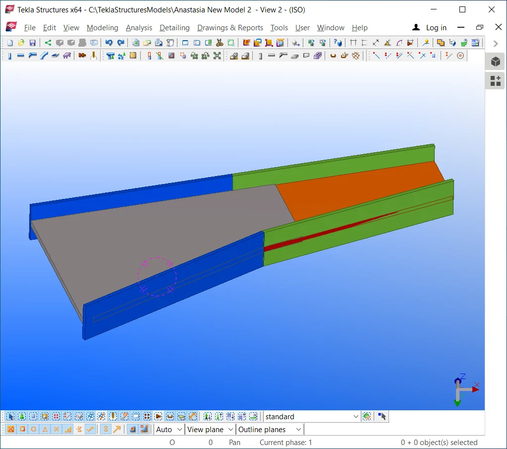
Thus we have created a non uniform cross section beam, defined by various
Weld on the parts by yourself by using an arbitrary welding chord size.