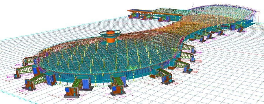
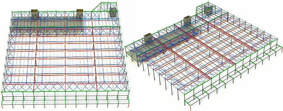
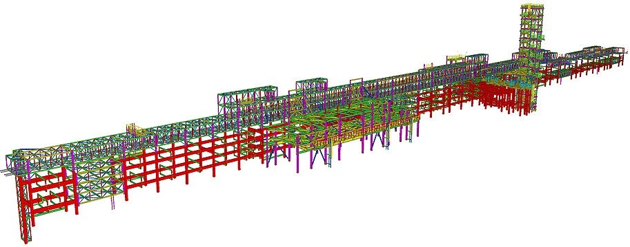
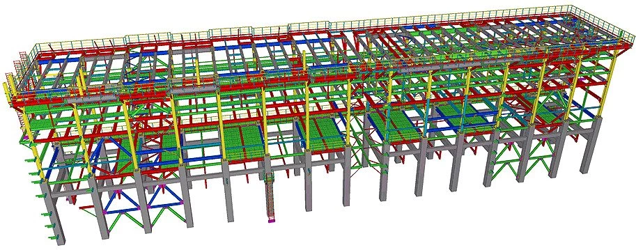
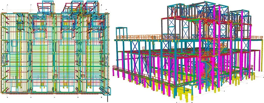
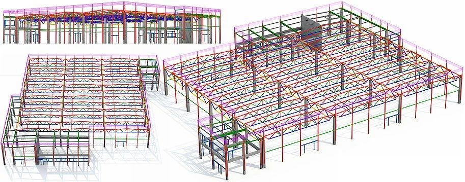
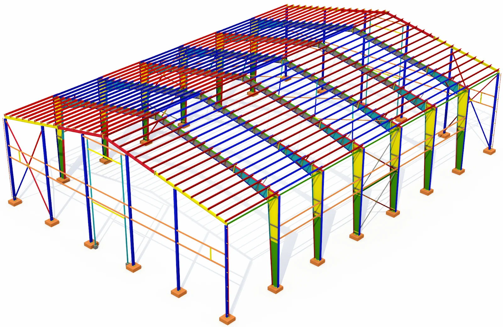
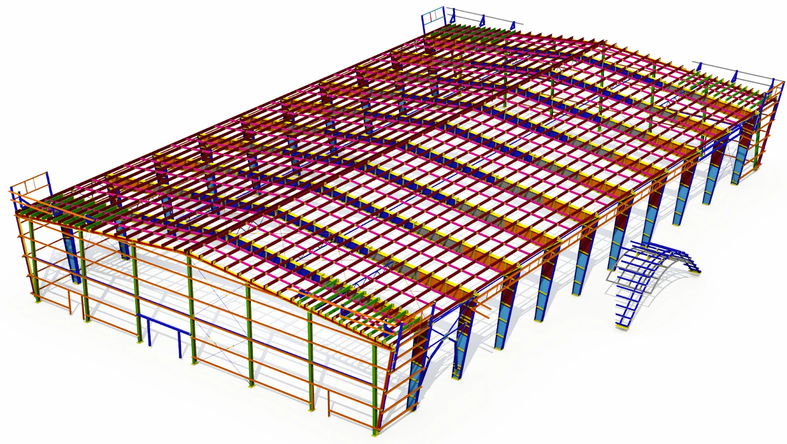
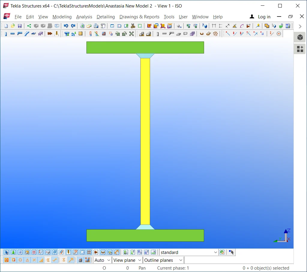
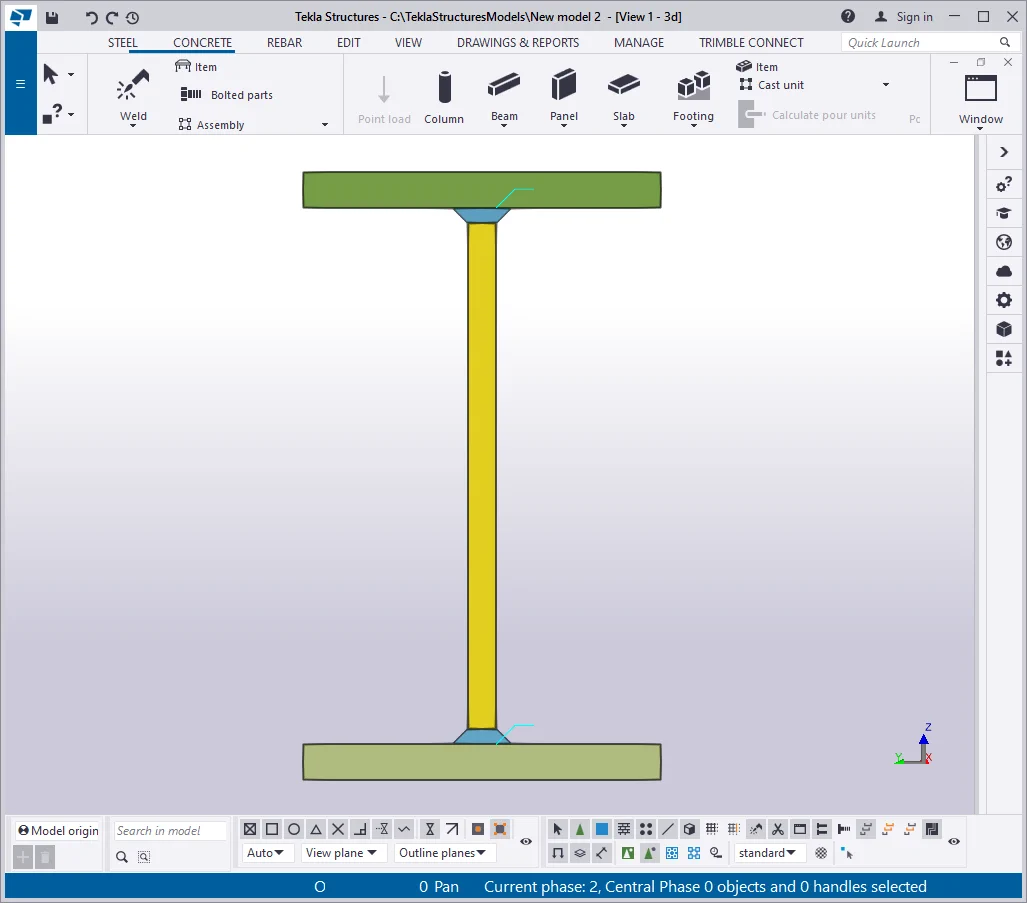
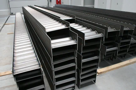
A non-uniform beam is a beam created of plate materials, which welded together into a profile of a constant or a variable cross-section. Thus profiles of such beams may fluctuate not only by length as well as by thickness. One of the typical examples of using non-uniform beams is presented below:
|
|
|
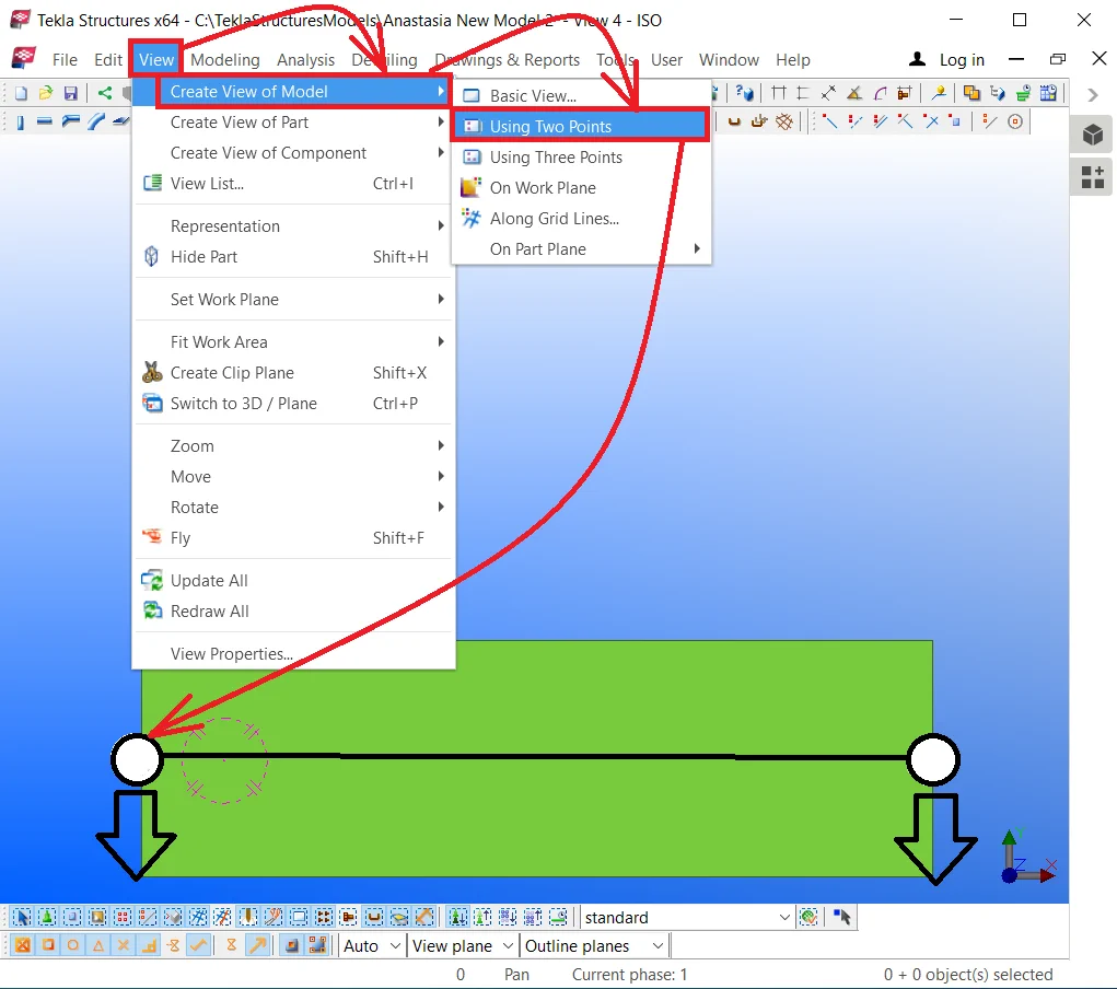
One of the basic ways for creating a non-uniform beam is to create a standard beam and respectively configure its profile. The non-uniform beams created by this method can be used for transmitting to the calculating software. Also, this method can be used if there is no need to separately take account of the materials used.
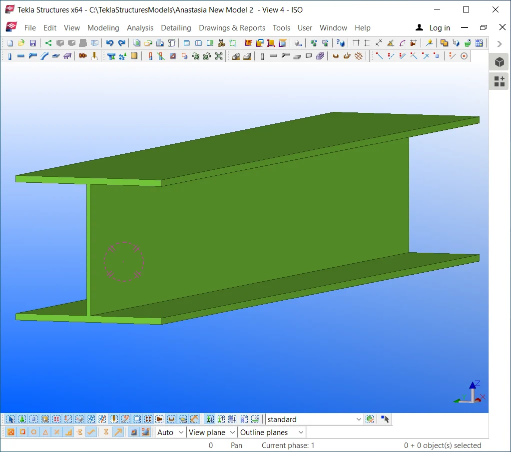
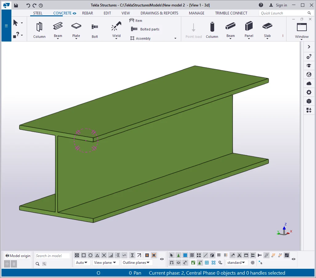
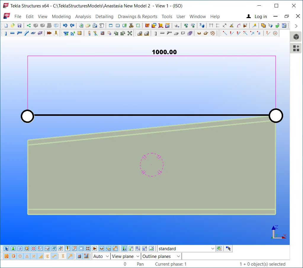
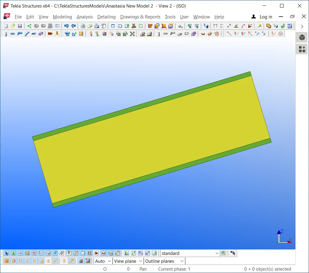
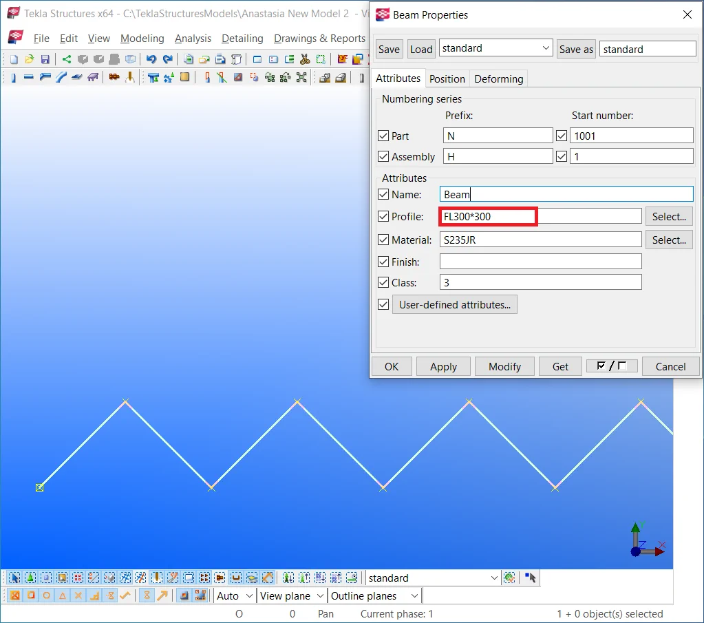
Create a simple beam of 1000 mm in length.
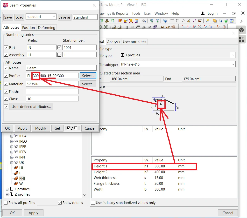
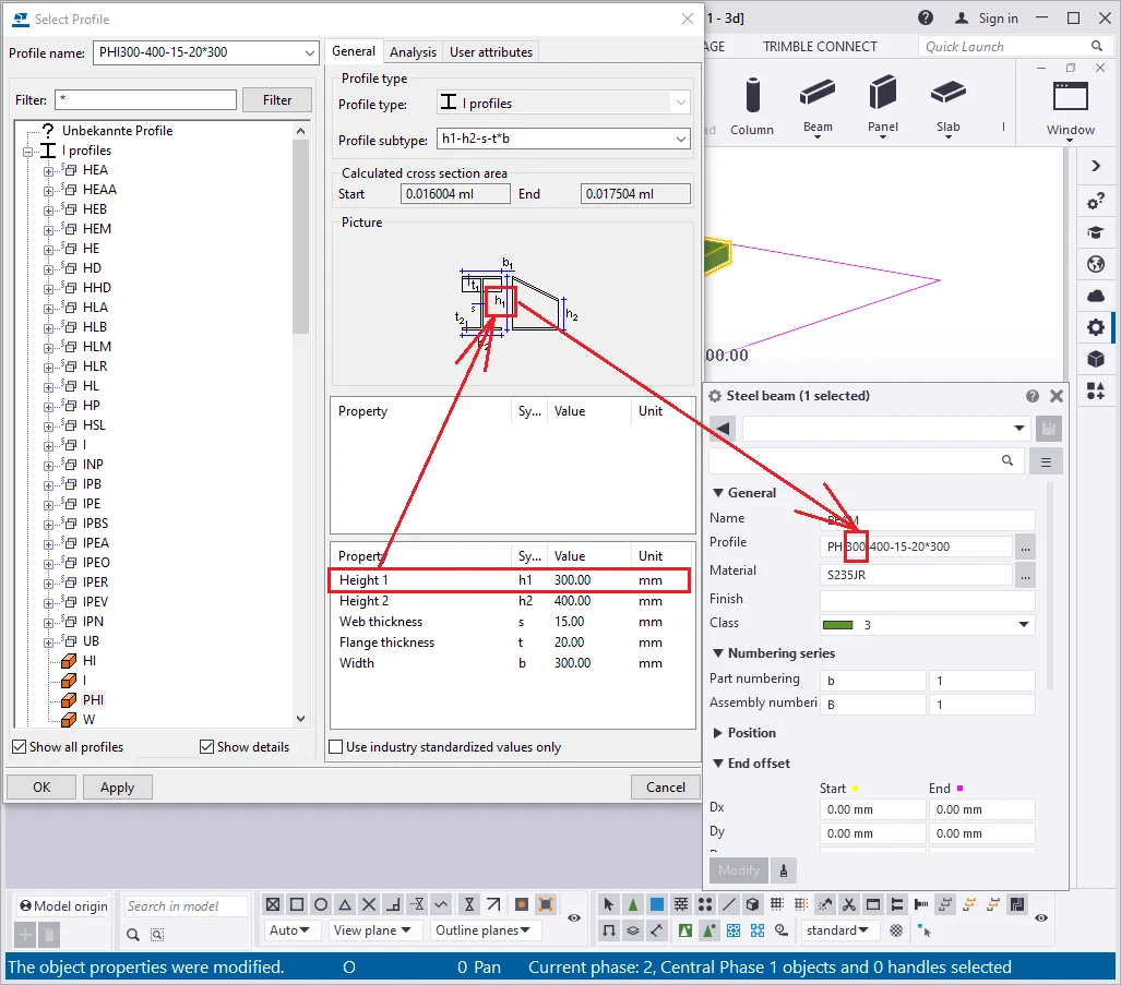
In the “Beam Properties” menu, go to the "Profile Catalogue" and write into the search box: “*PHI”.

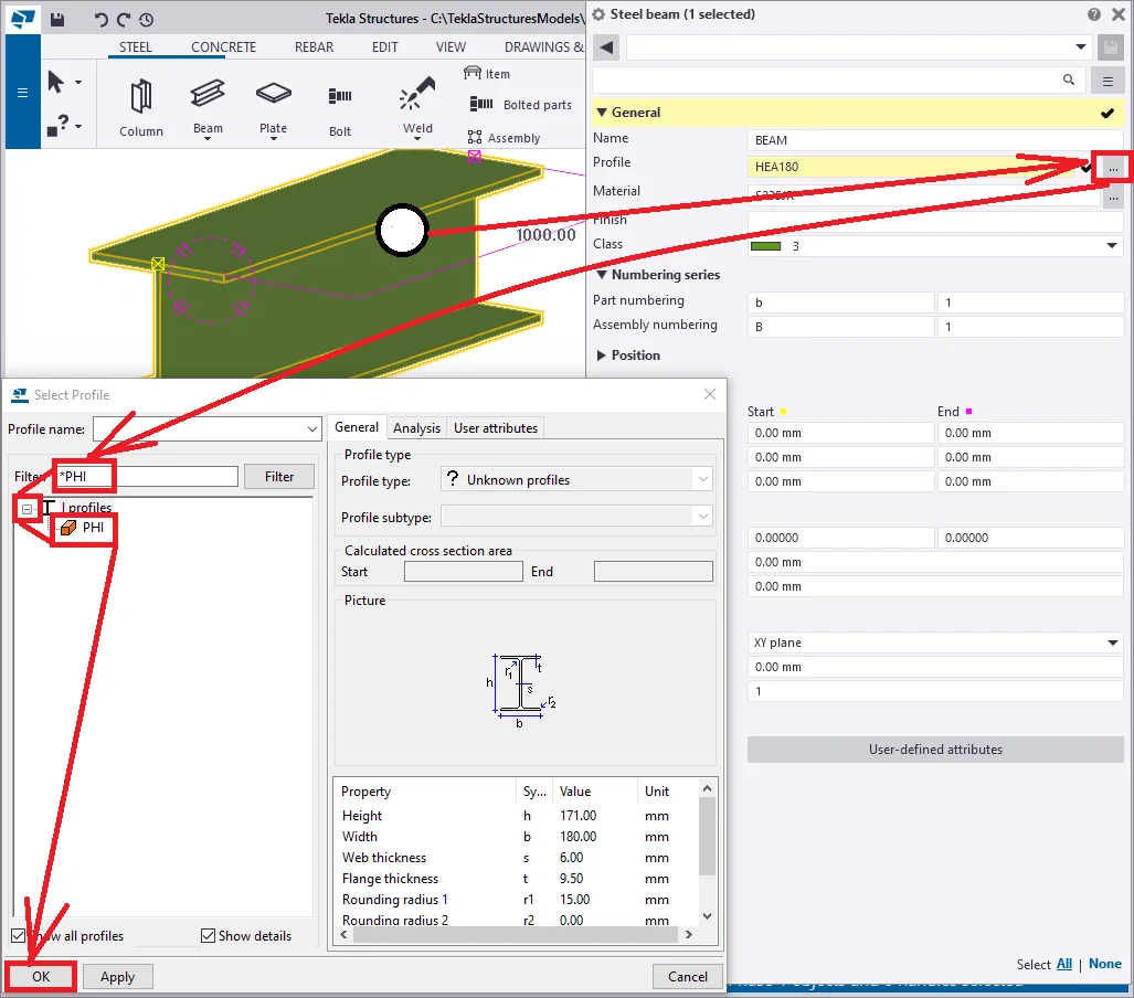
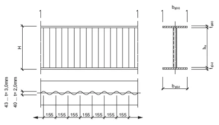
This profile type is defined by I-beam height variance at its starting and endpoints. It allows setting out the I-beam's height at its starting point and the I-beam's height at its endpoint. In the below picture you can see the table with editable profile parameters.
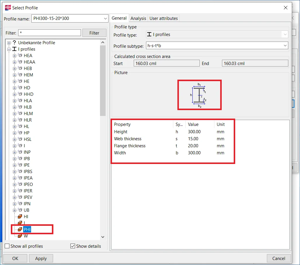

Set the beam's profile at “PHI300-400-15-20*300”.
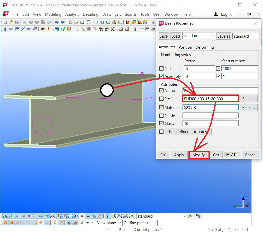
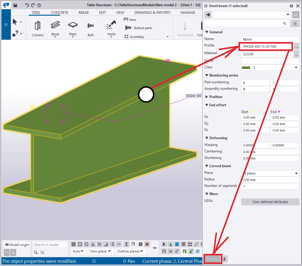
The profile title reflects all the parameters which shape the beam and
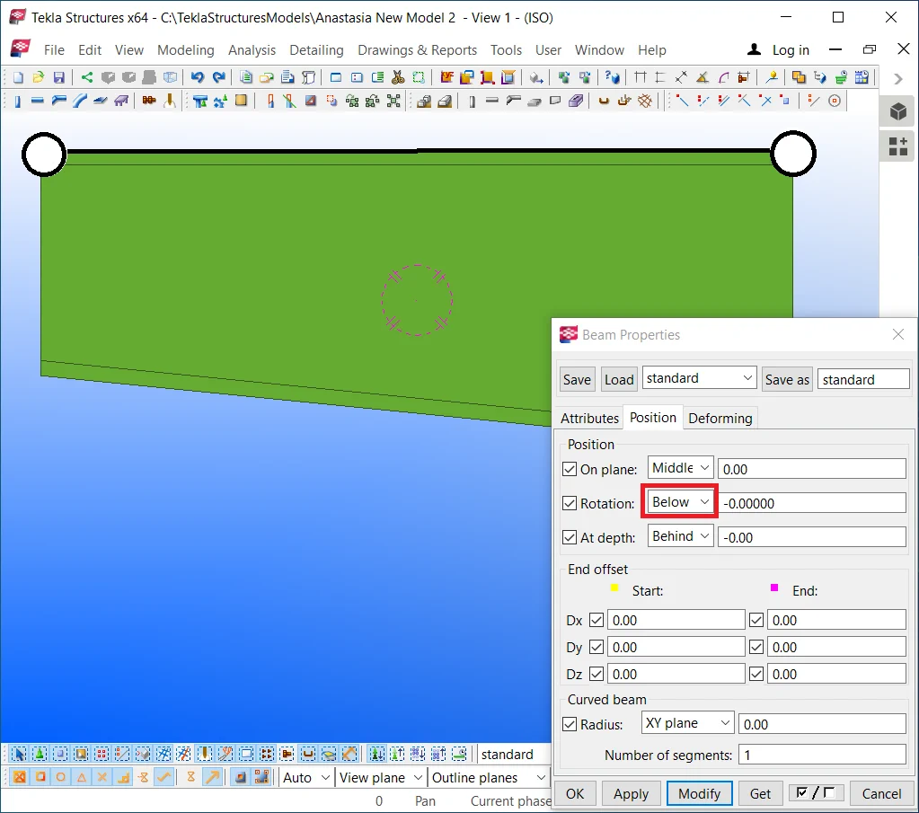
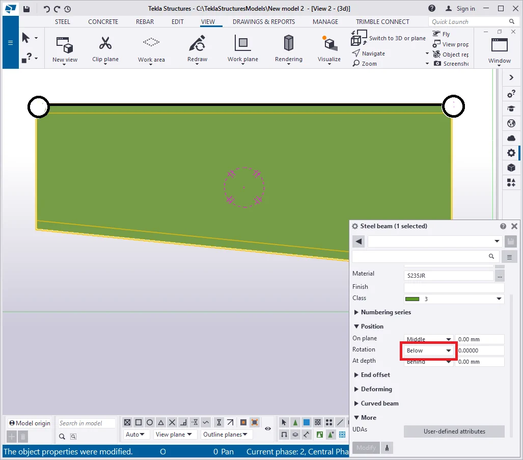
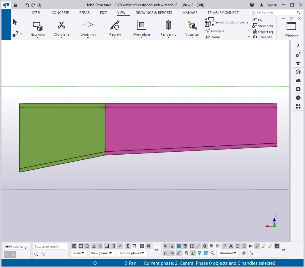
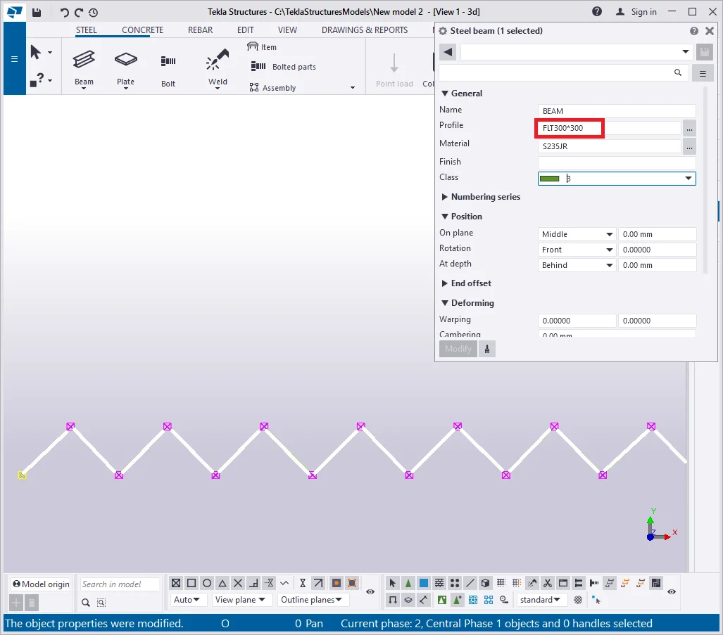
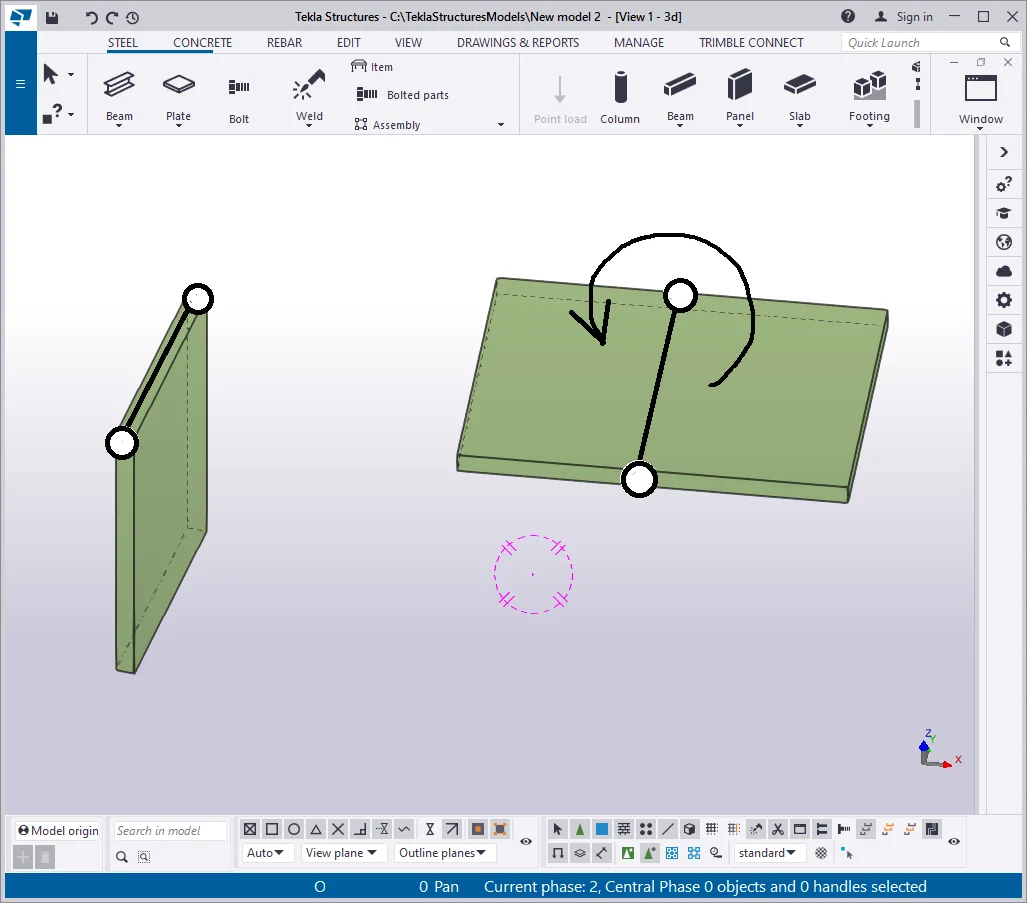
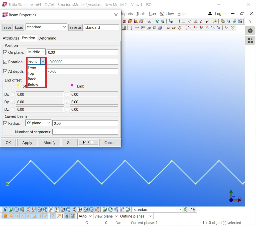
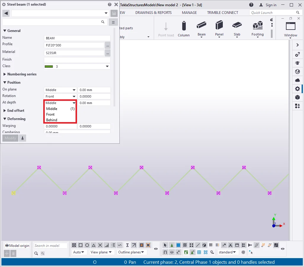
Depending on the beam's "Rotation" default settings, the real segment which we indicate, when creating a beam, can be above or below the beam's body.

Go to the 'Beam properties" menu and configure the "Rotation" parameter to the “Below”, to ensure coinciding of the building up segment with the I-beams profile straight line. Thus changing the beam’s profile will keep its top part unmoved.
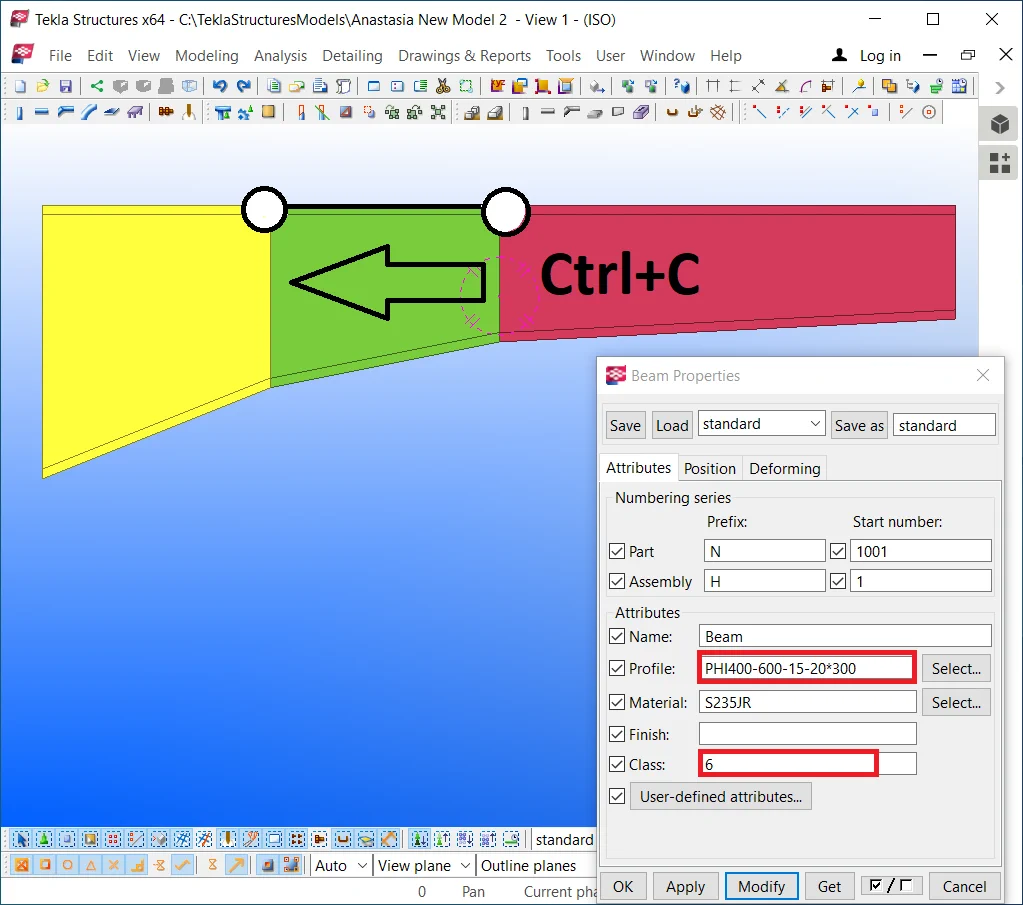
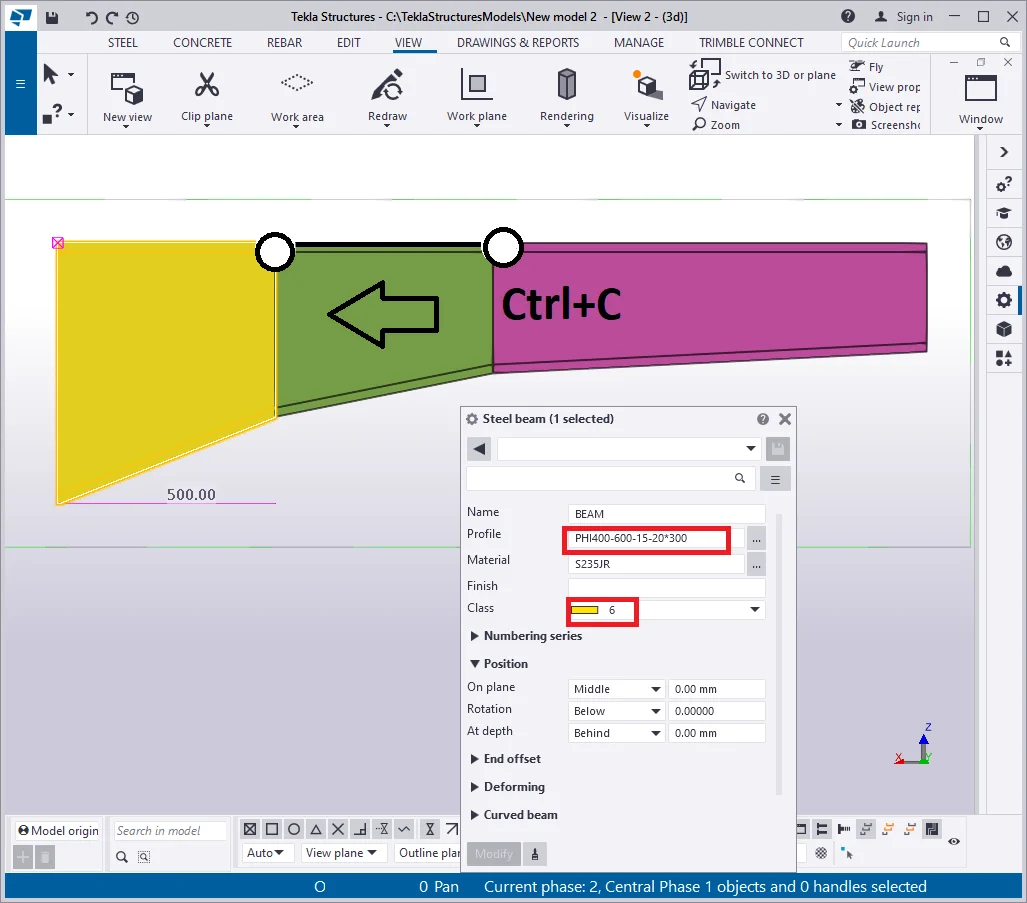
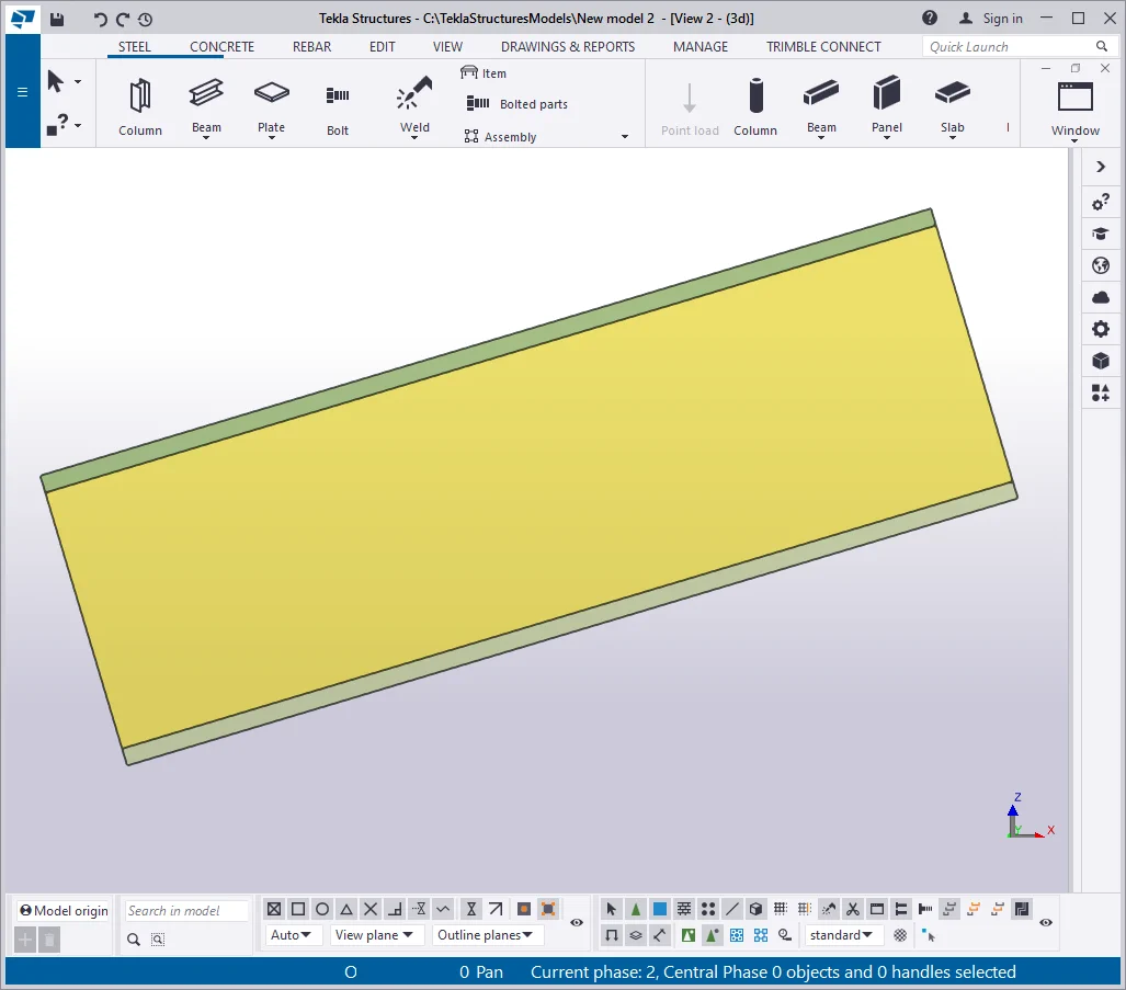
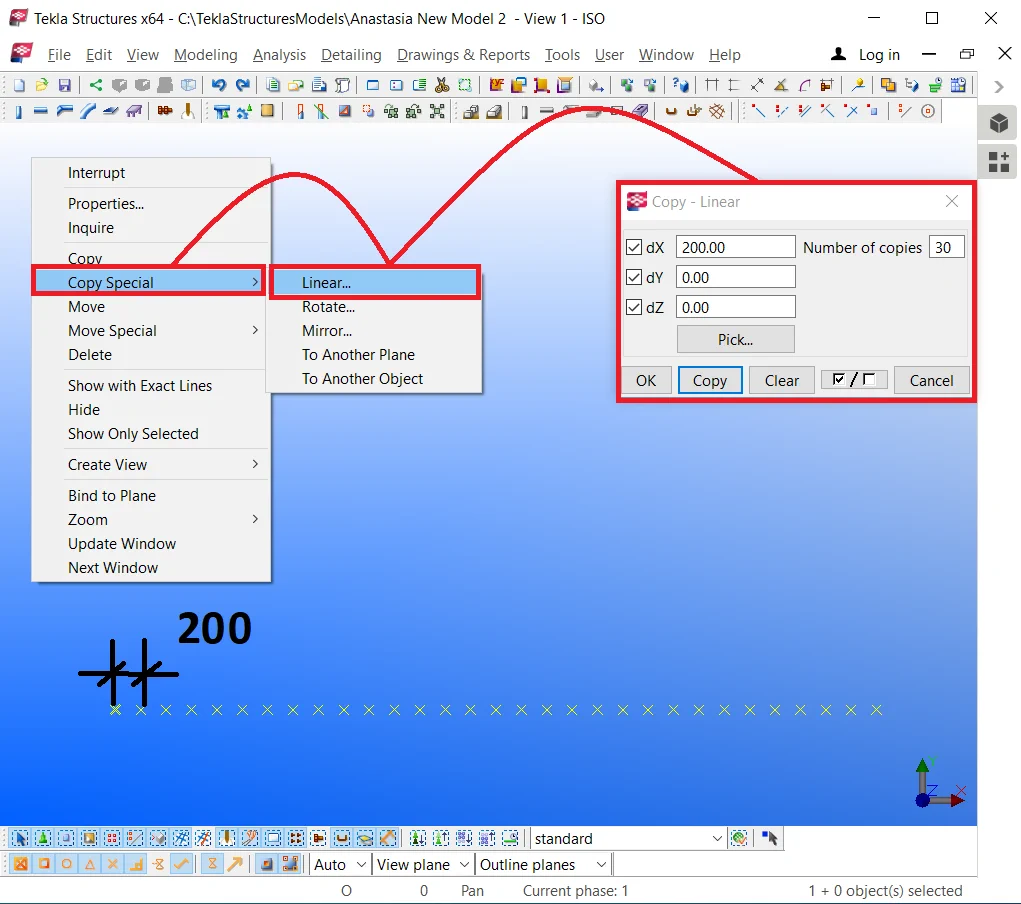
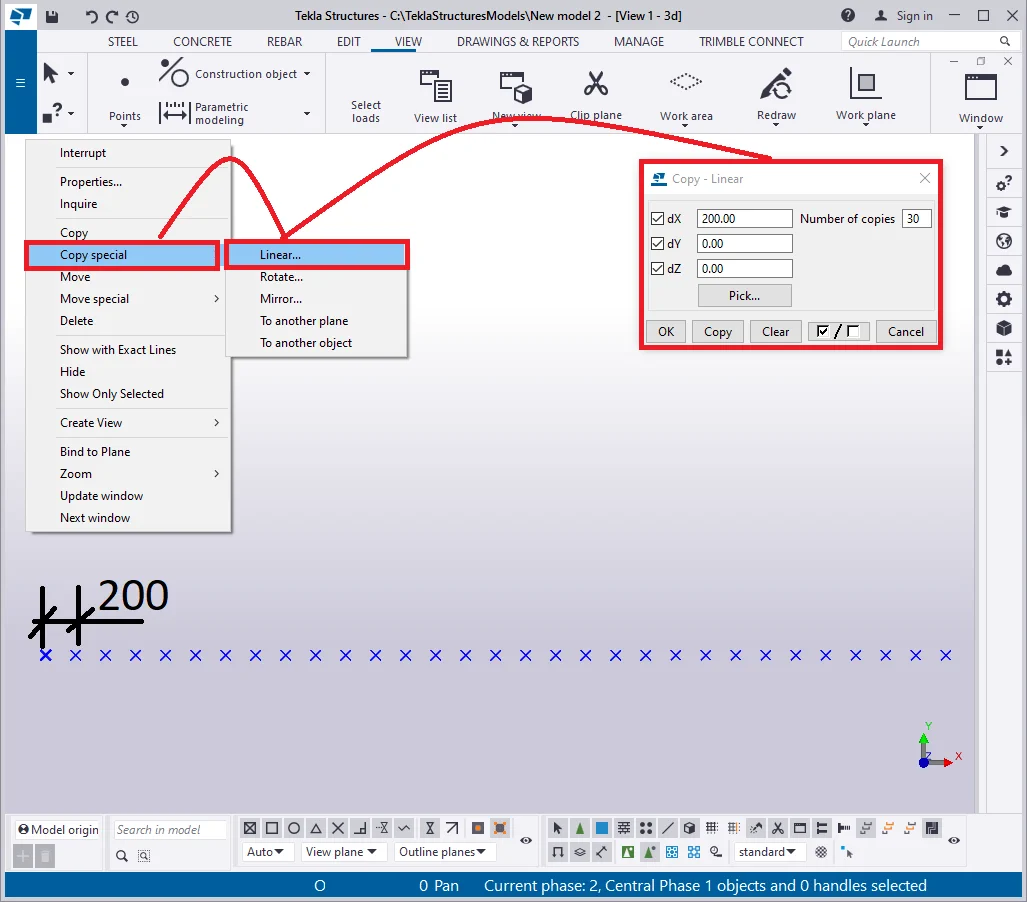
Select the beam and copy it horizontally by using the Ctrl+C hotkey combination.
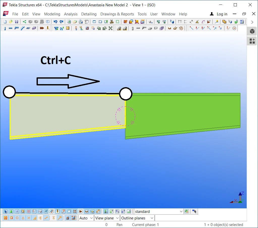
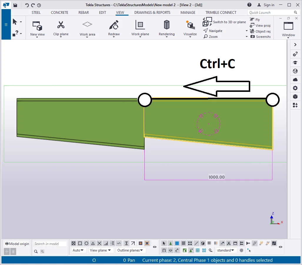
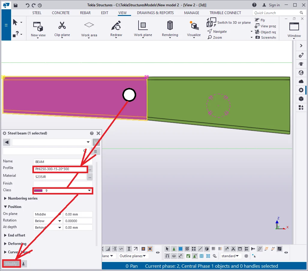
Select the new beam and adjust its profile in the way its cross-section height at the juncture point to be equal with the respective of the initial beam. Thus write in the profile type as “PHI250-300-15-20*300”, and change its class to 9, to assure better visibility between the beams.

Note that the beam's cross-section values are fixed at its starting
and endpoints, thus changing the beam’s length value does not affect
cross sections at all.
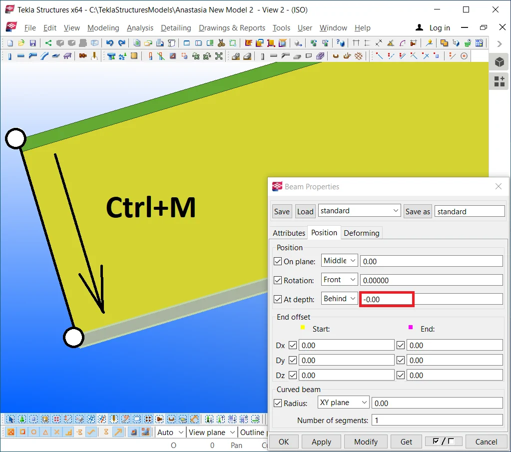
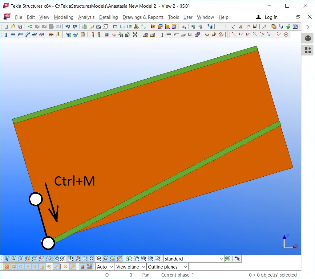
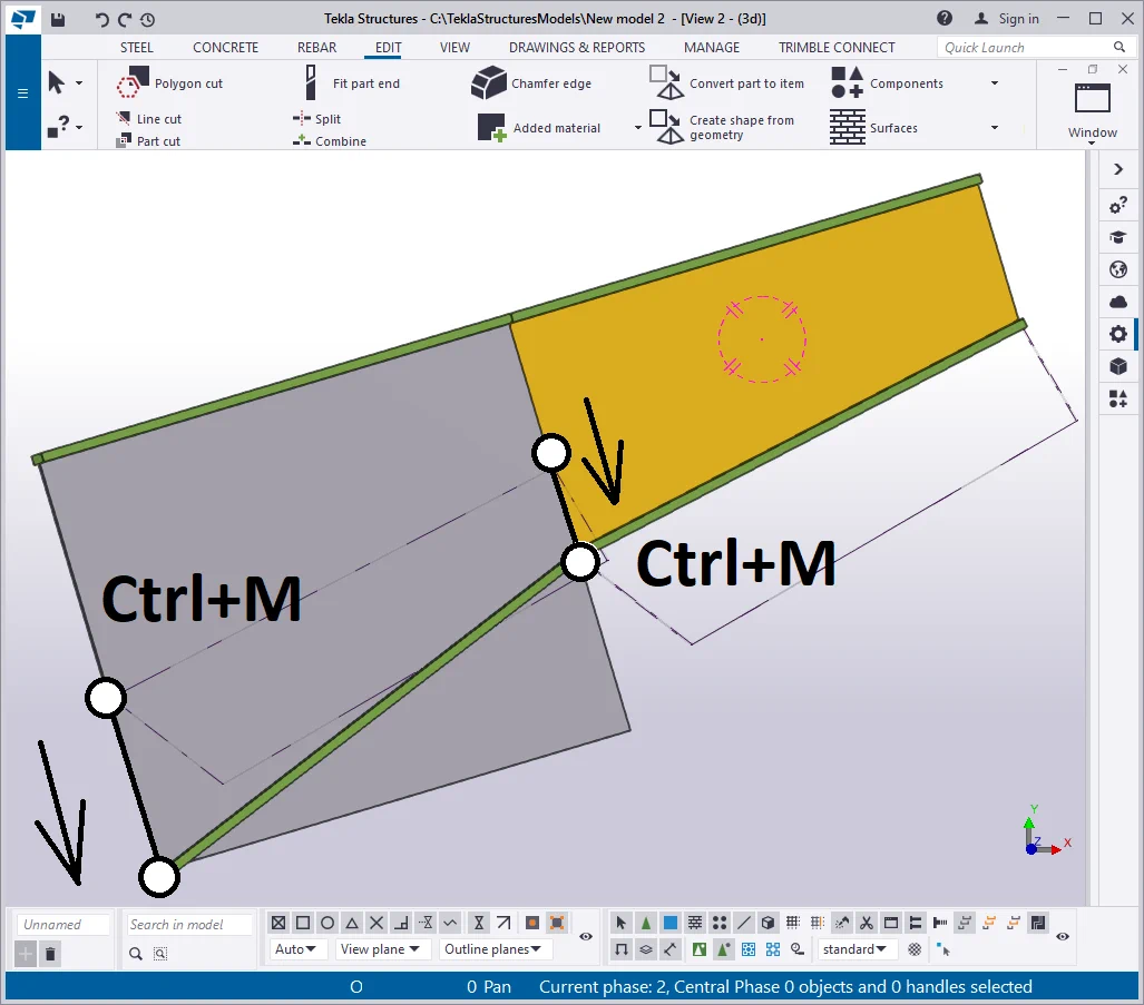
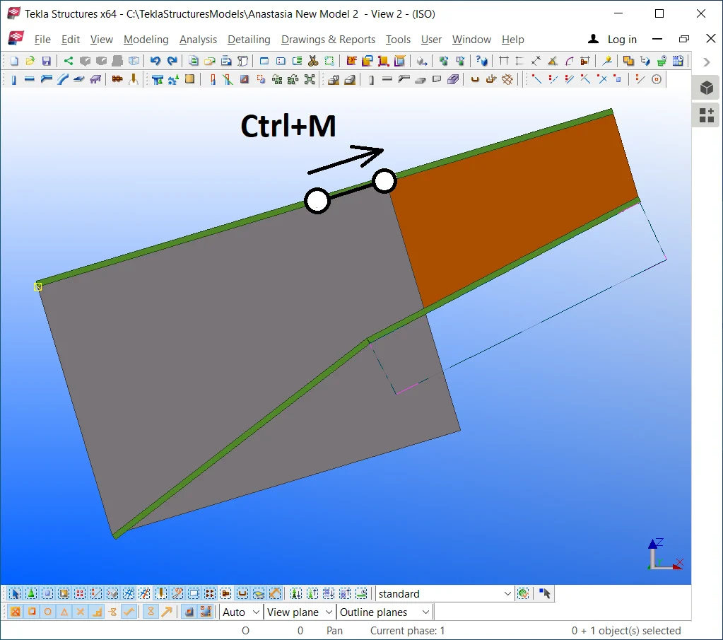
Click on the initial beam, select its right point, and by using the Ctrl+M
hotkey combination, move it to the left at 500mm.
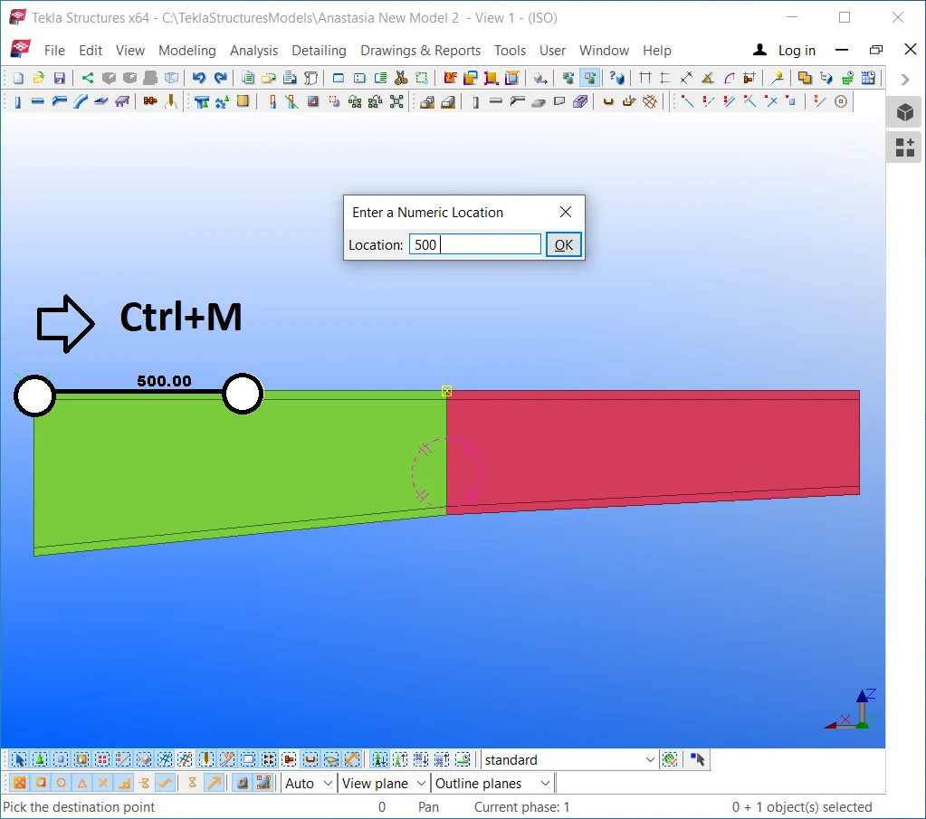
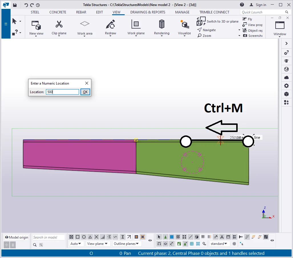
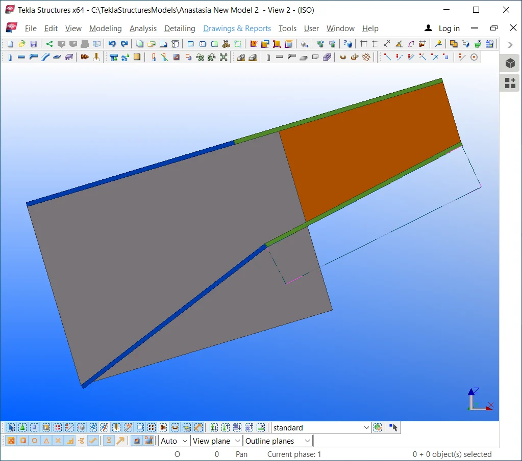
The beam has shortened, but the profile’s cross-section values remain

Copy/Paste the initial beam to the left, and configure its profile to
Advantages
Disadvantages
The consecutive method is a more intense one though the most correct for building up welded uniform cross section beams. It is important to consider that in practice real profiles are created of rolled metals, provisionally cutted and welded on to get the I-beam shape.
Thus it is of a high importance to consider the rolled metal in the statements as well as execute modelling the I-beams of the rolled metal sheets. It is possible to create rolled metal drawn up by a polygon, but in this case we will have to manipulate many points, which is not a convenient situation.
Thus during modelling non uniform cross section beams it is more convenient to use the beam tool configured at a specific profile type, which is considered in the material statements as rolled metal.
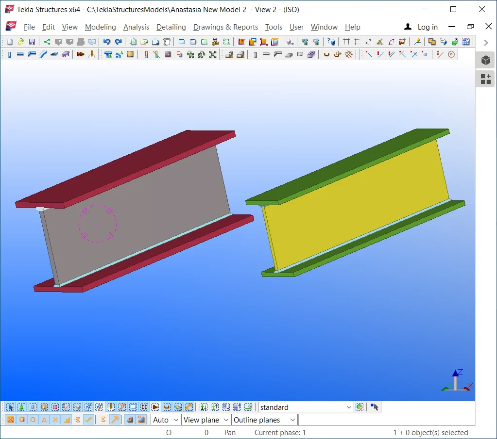
Let’s firstly create an uniform cross-section beam, which geometrically is similar to a standard beam, but is composed of 3 distinct rolled metal sheets welded on togher into an assembly.
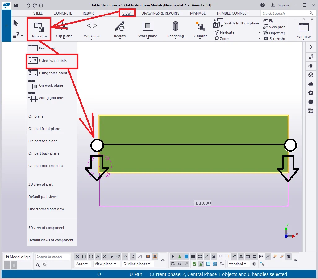
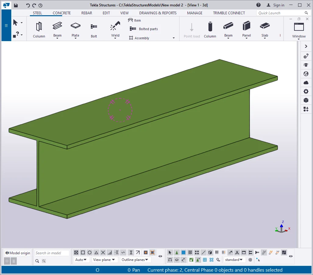
Go to the view plane and create a simple beam of 1000 mm length.
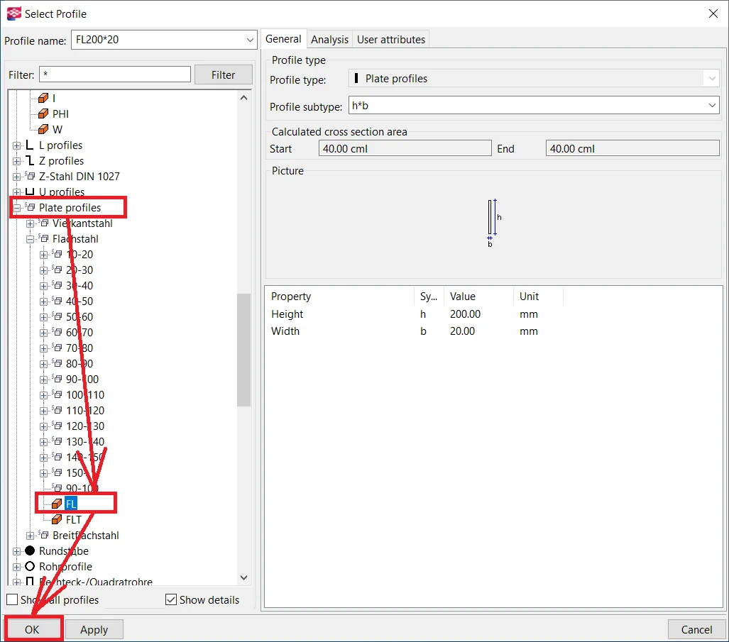
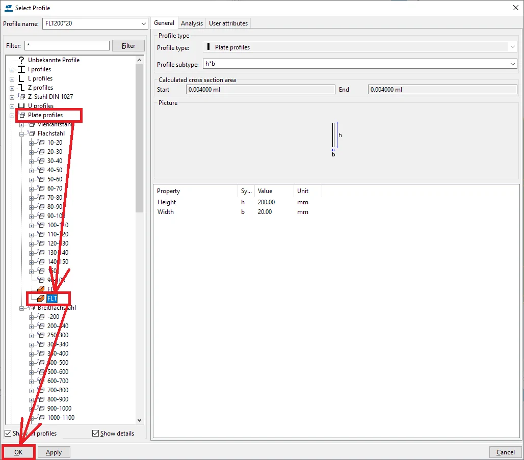
At the "Profile catalog", select the parametric plate profile.
Depending on the localization package of the Tekla Structures, there might be various titles set out for these profile types. These profiles are necessary for substituting the wide profile range. Thus for modeling a rolled metal list, is it sufficient to indicate only the length and width parameters for the initial sheet part.
Except for executing modeling rolled metal sheets, it is not recommended to use parametric profiles, as they do not contain any ISO information and other service system information.
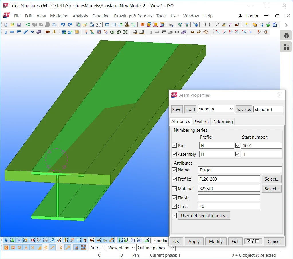
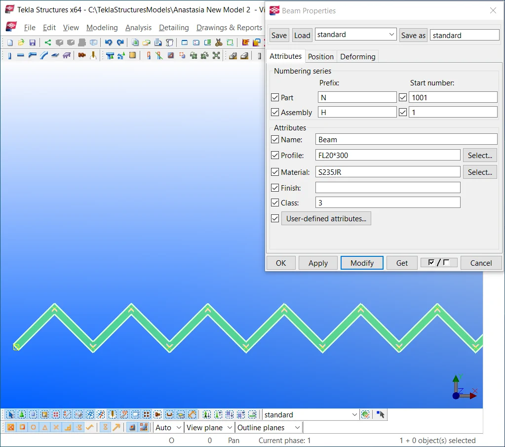
Let’s apply the selected profile to our model. Pay attention to the fact that the first digit stands for the thickness parameter of the part, not its width. In the below picture you can see the very error committed. Thus in the rolled metal specification, a sheet of 200 mm thickness is indicated. Write into the profile field the thickness value first, but the width value right after the symbol “*”.
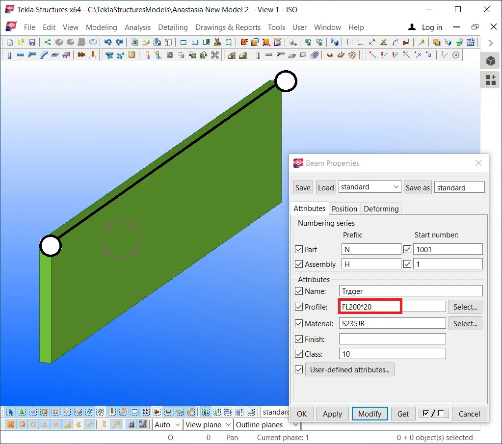
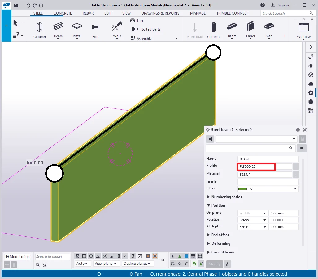
Make sure that the first digit is of the smallest value.
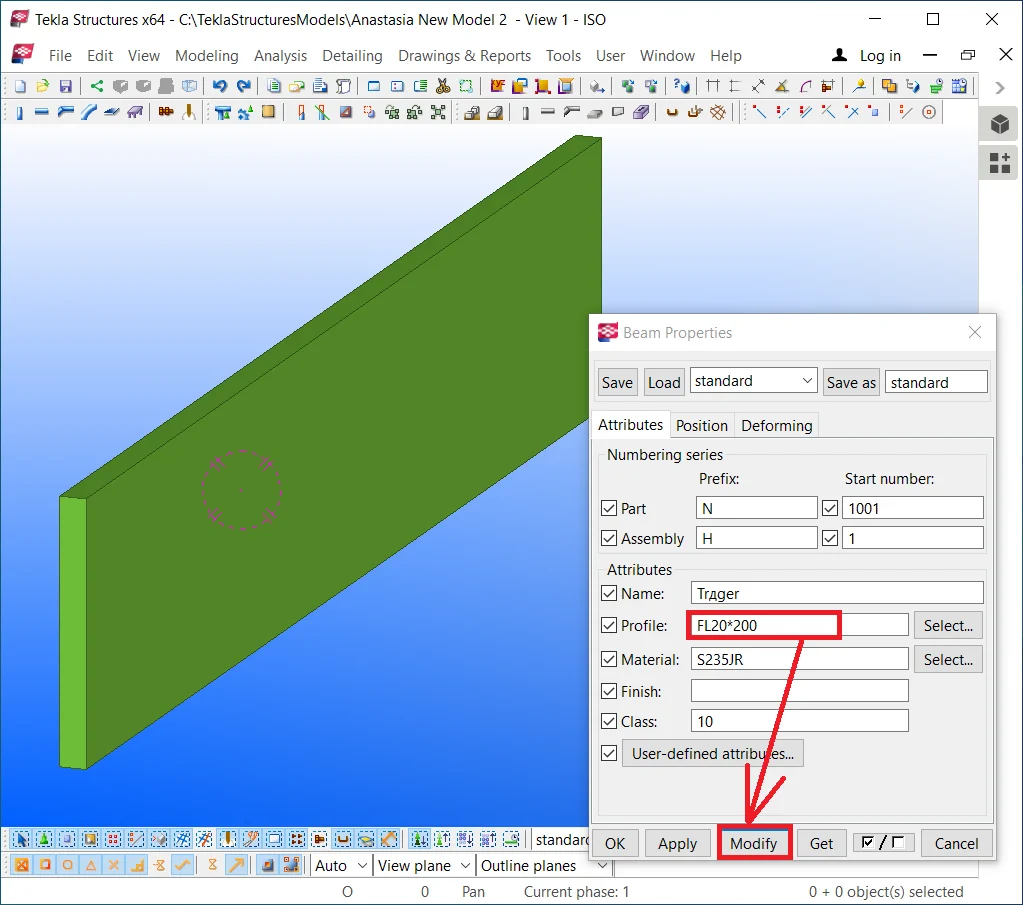
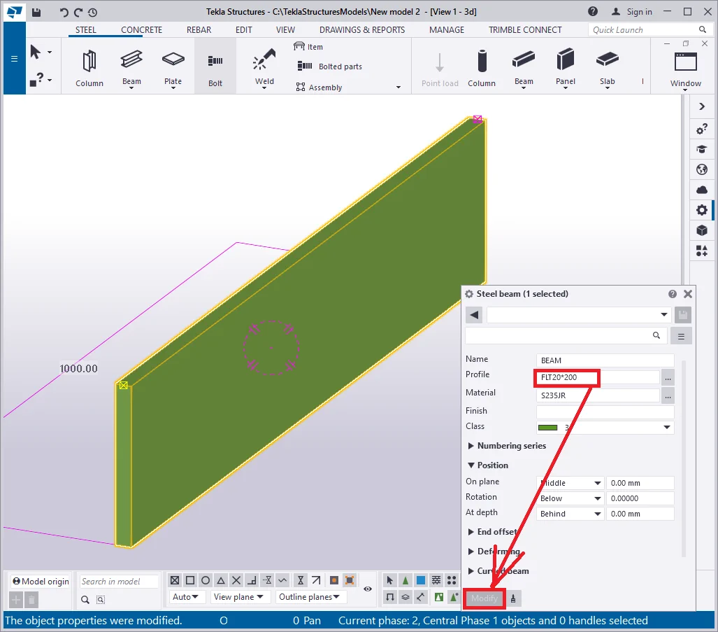
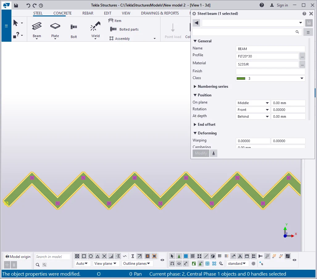
Subsequent to pressing the “Modify” button, you can see no visual changes in the model, but it is of a high essence for creating the material reports and statements: we use the material of 20 mm thickness, but not of 200mm: “—20*200”.
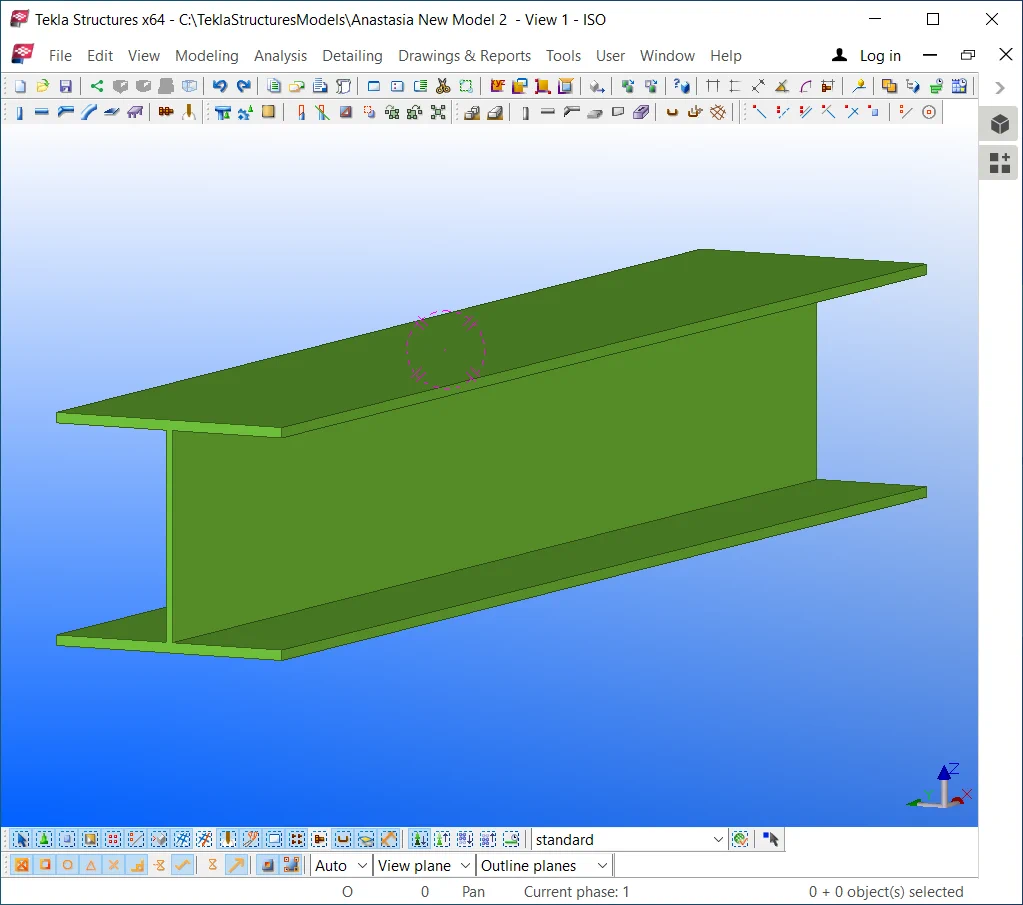
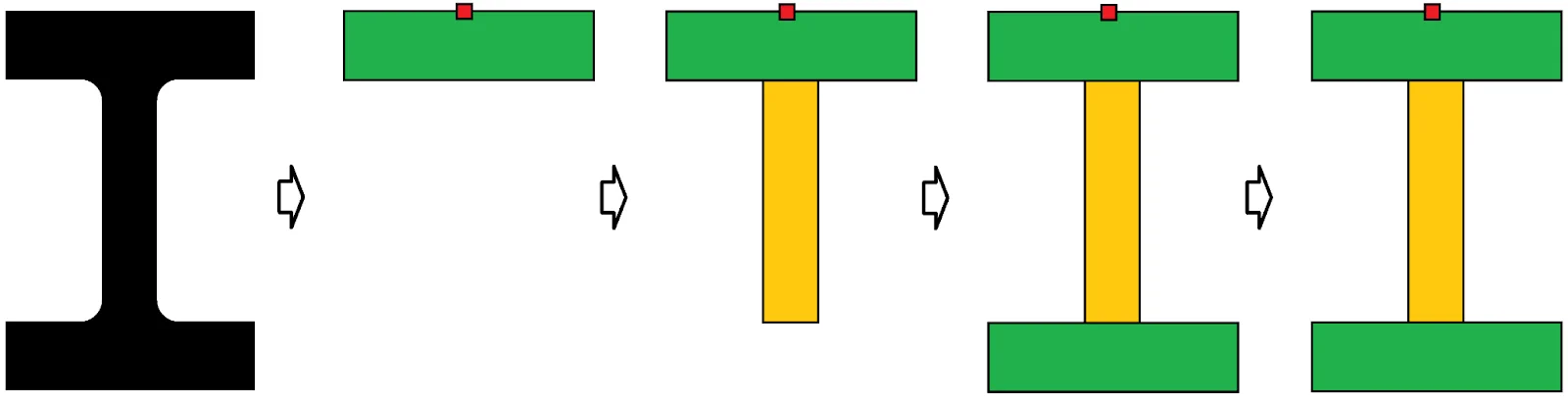
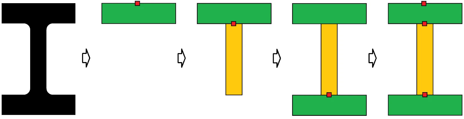
Rotate the part created in the way to see it into the I-beam flange position.
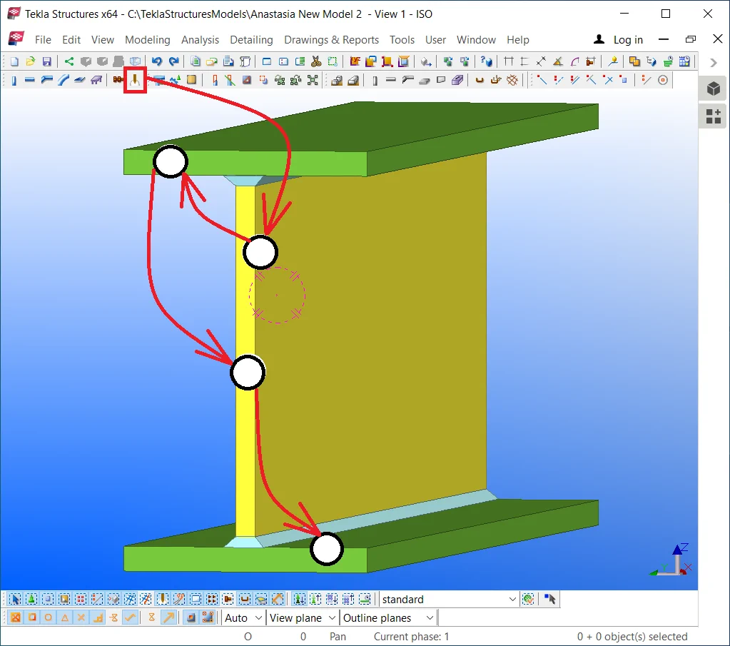
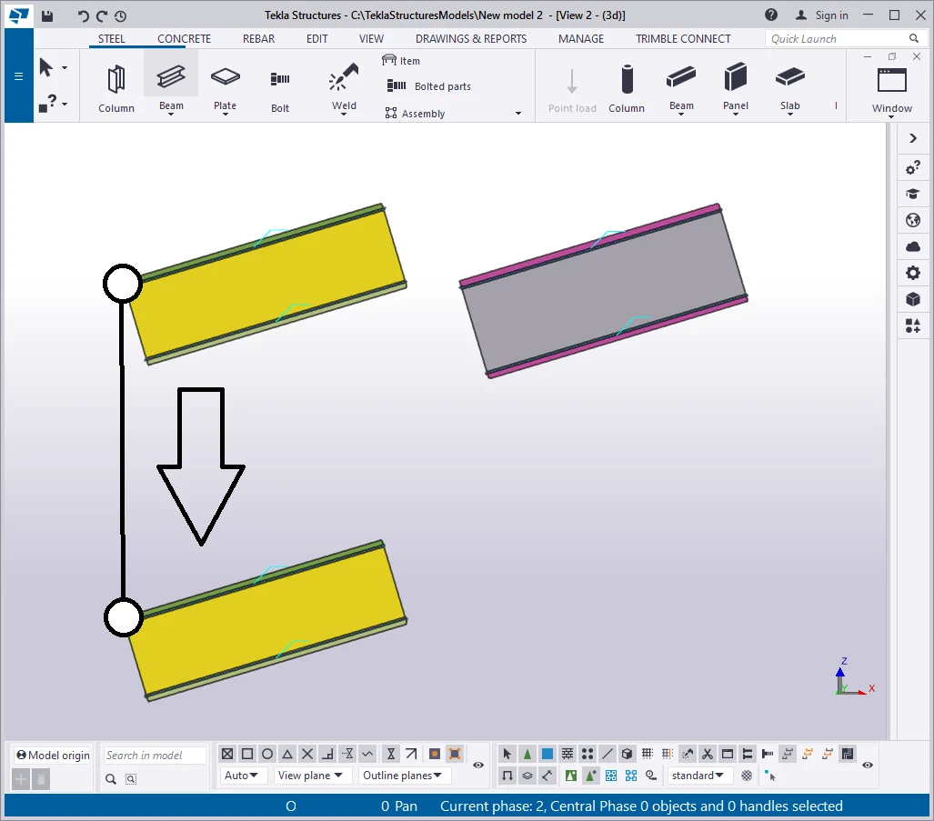
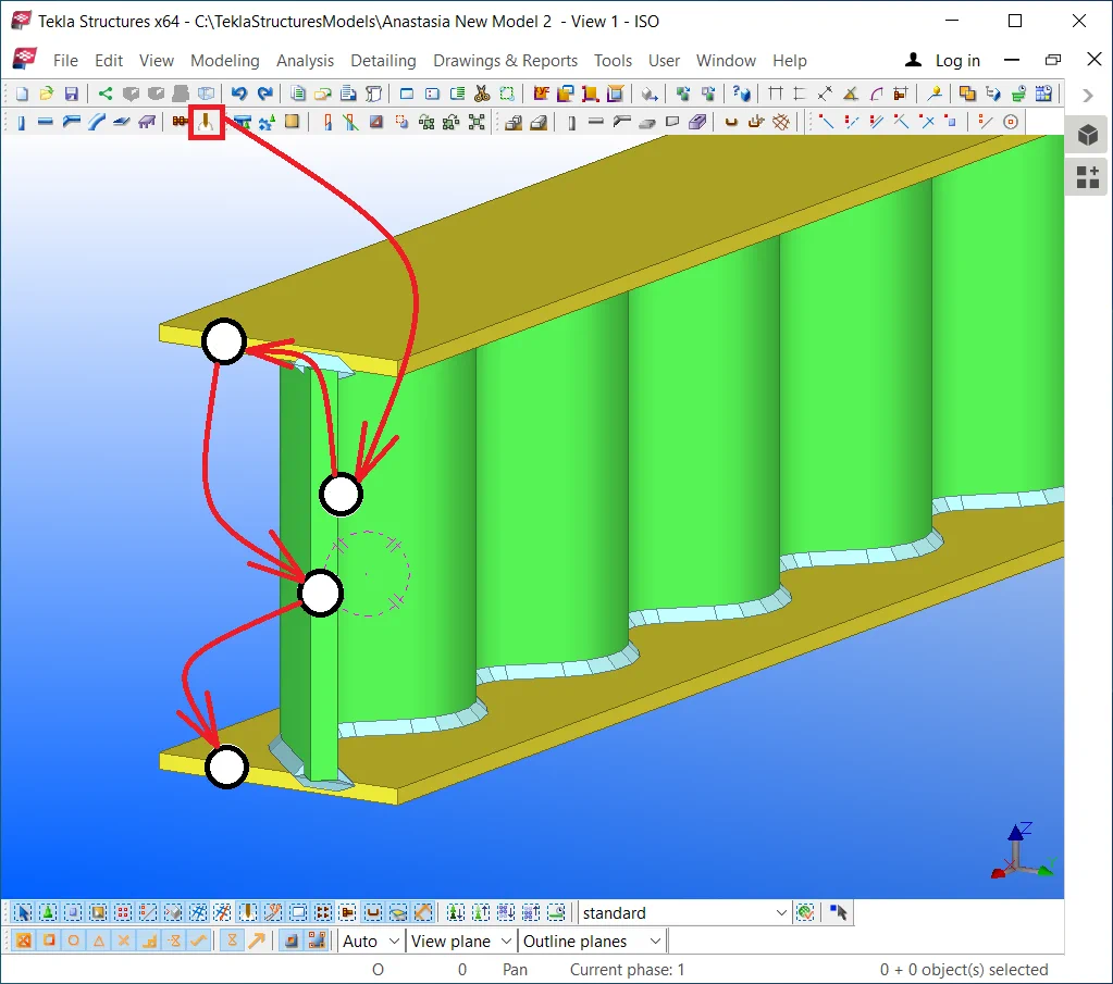
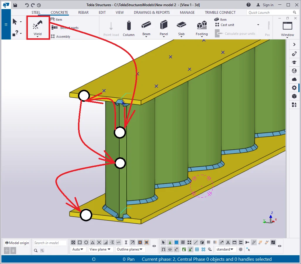
The scheme for substituting the rolled metal profile at a welded uniform cross-section beam. Redpoint stands for indicating the building up line of each profile with account for the offset.
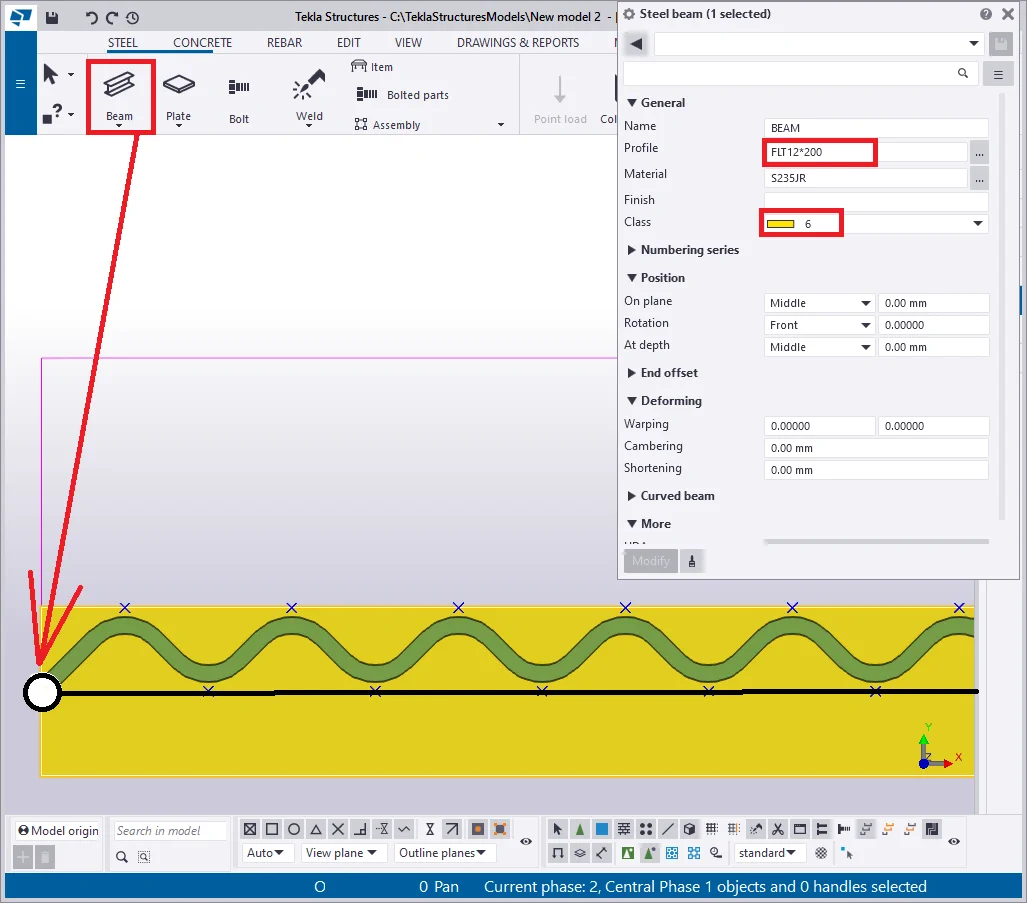
Select the object and draw up a new beam by taking the account of the
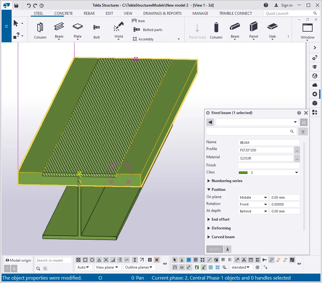
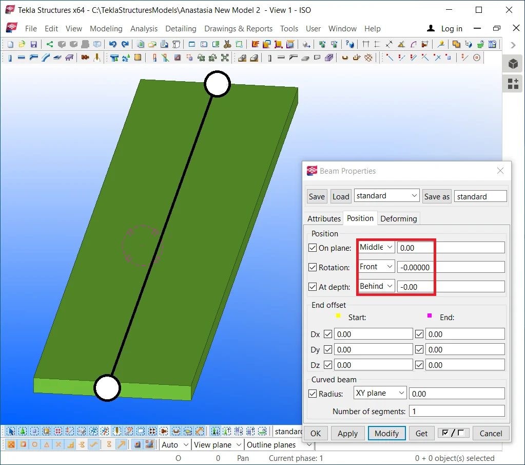
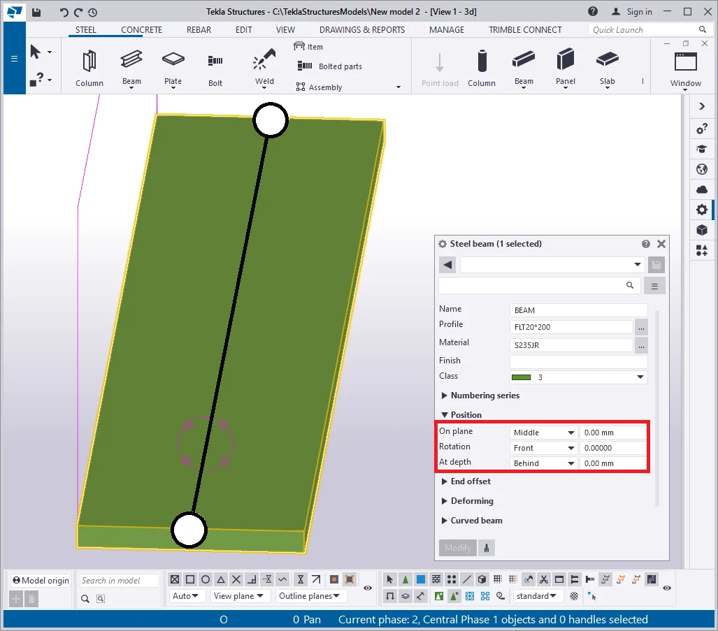
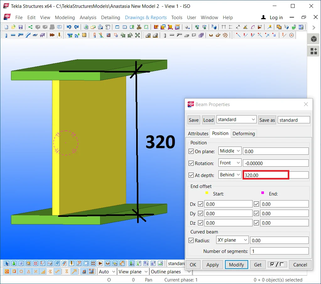
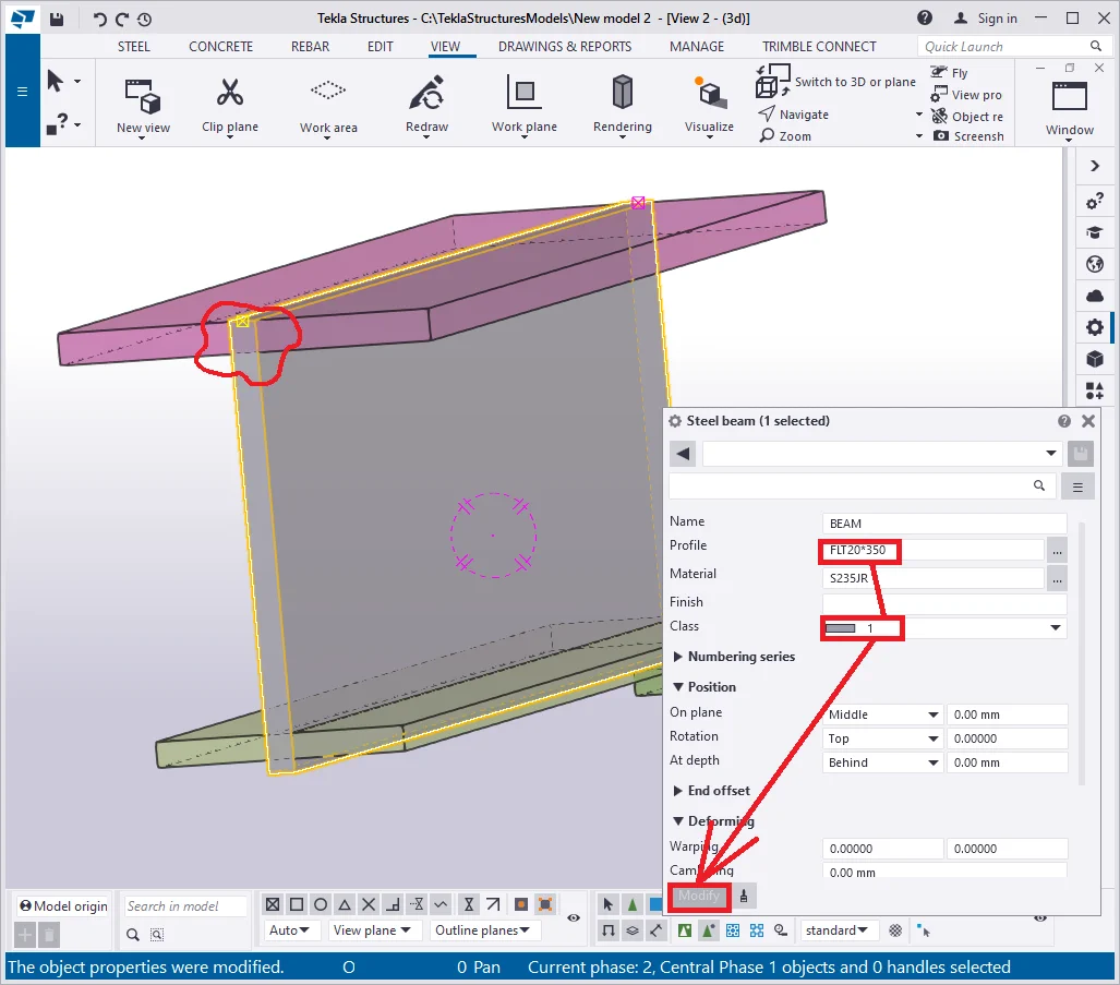
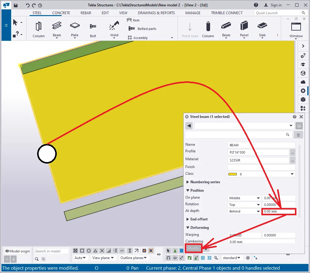
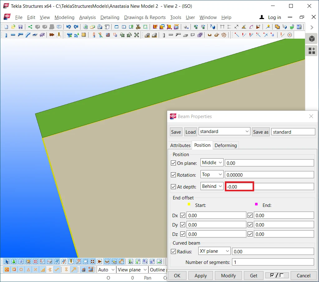
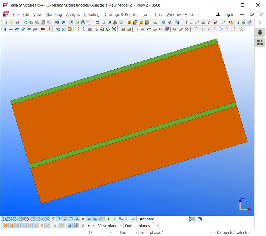
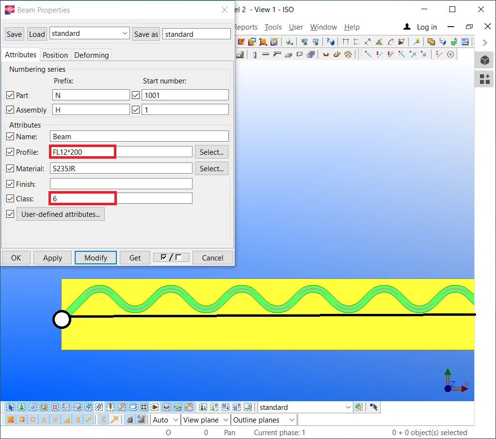
Change the beam's profile to “—16*300” and its class to 6 (yellow). Set out by your own the position parameter values concerning the profile reference line.
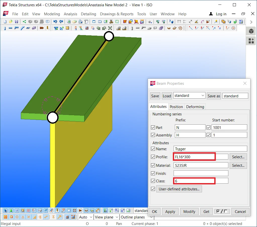

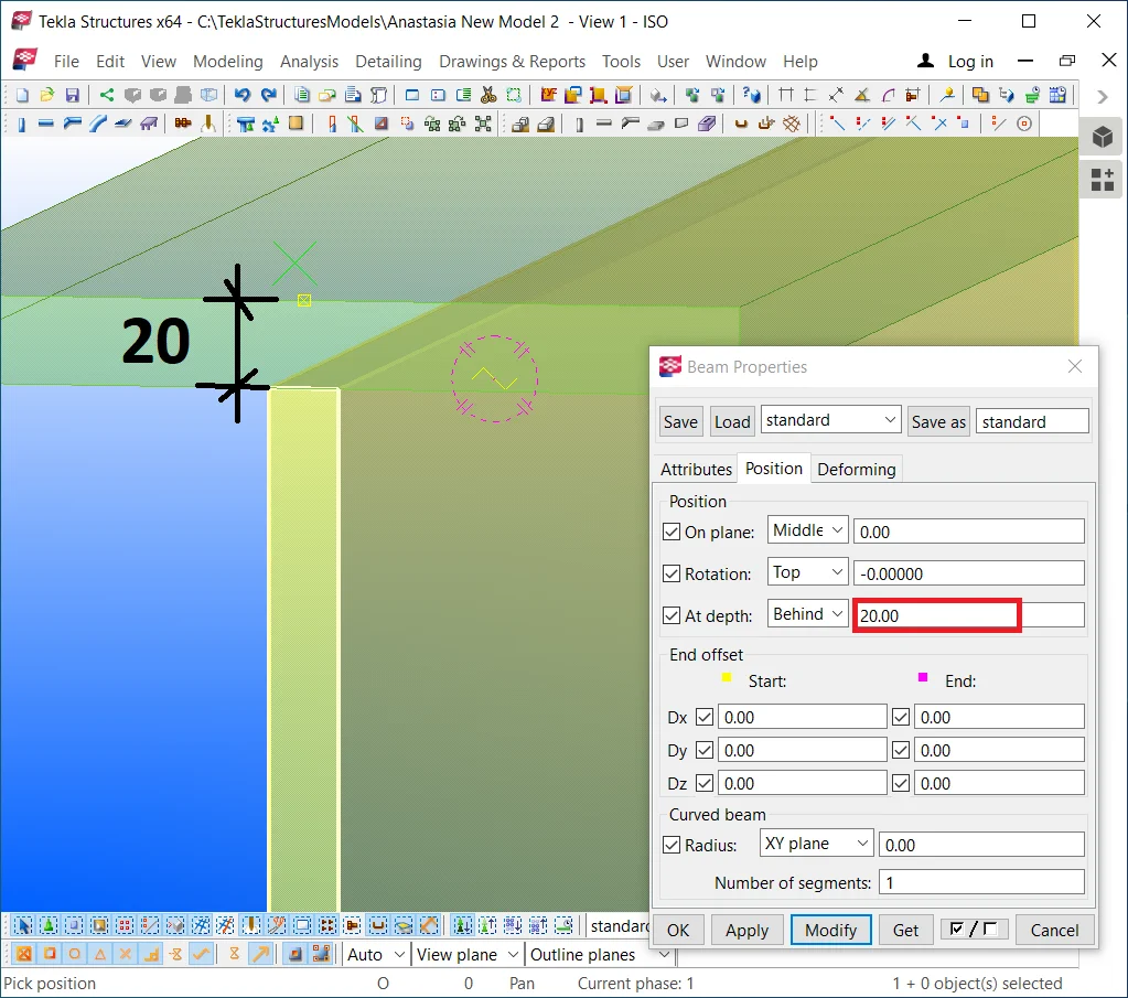
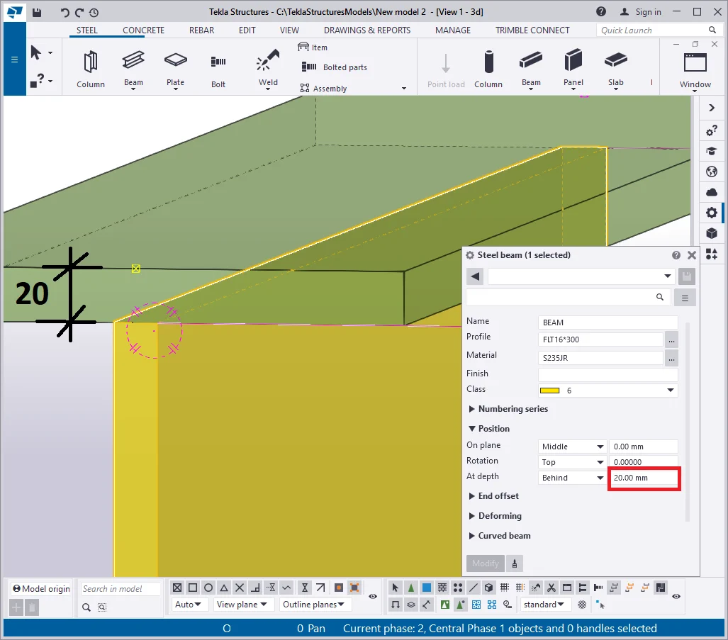
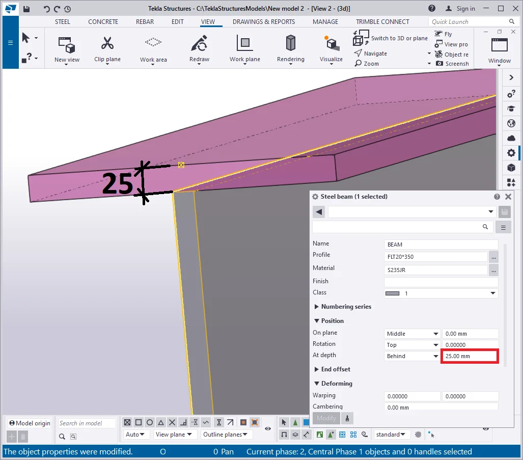
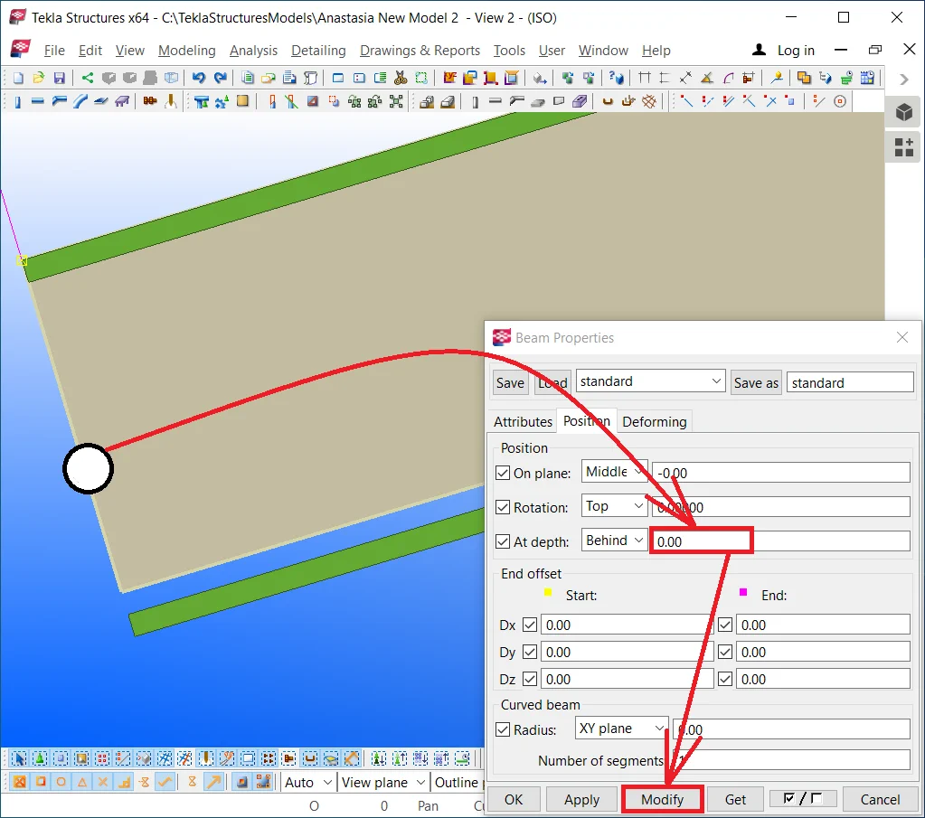
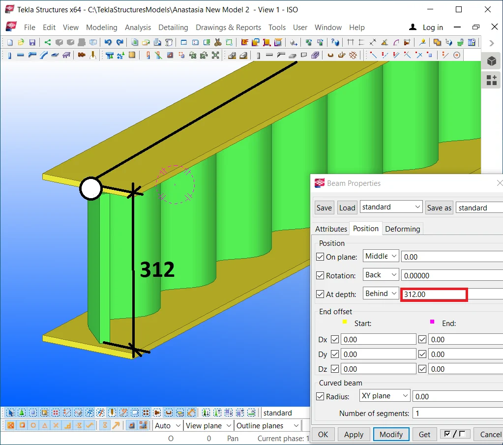
Configure the “At depth” value as it is shown below:
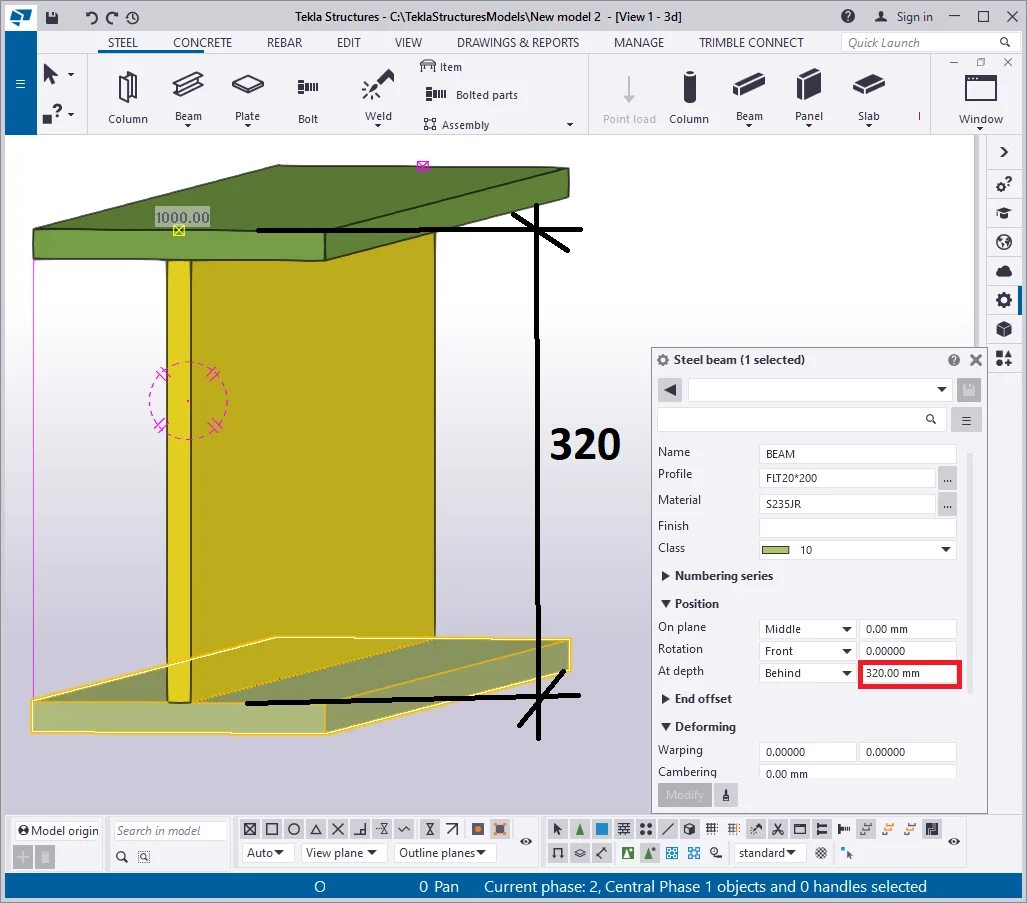
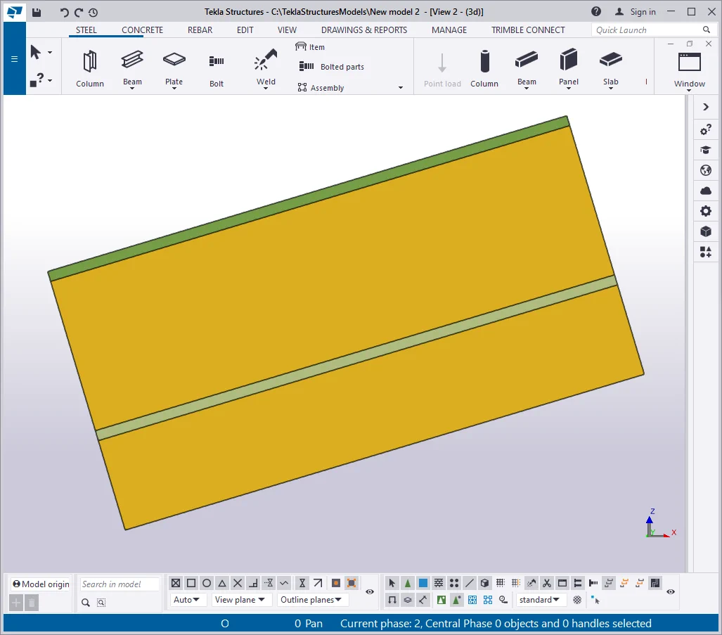
Select the upper flange part. Create one more beam taking into account the reference line of the initial object and its starting and endpoint sequence.
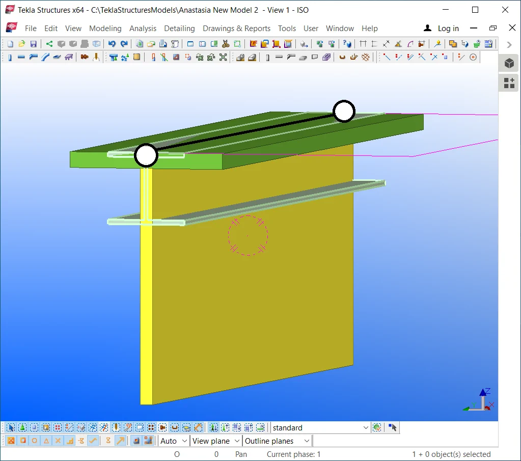

Configure the new beam’s profile similar to the upper flange, indicating
Let’s weld up parts into an assembly, where the beam's wall
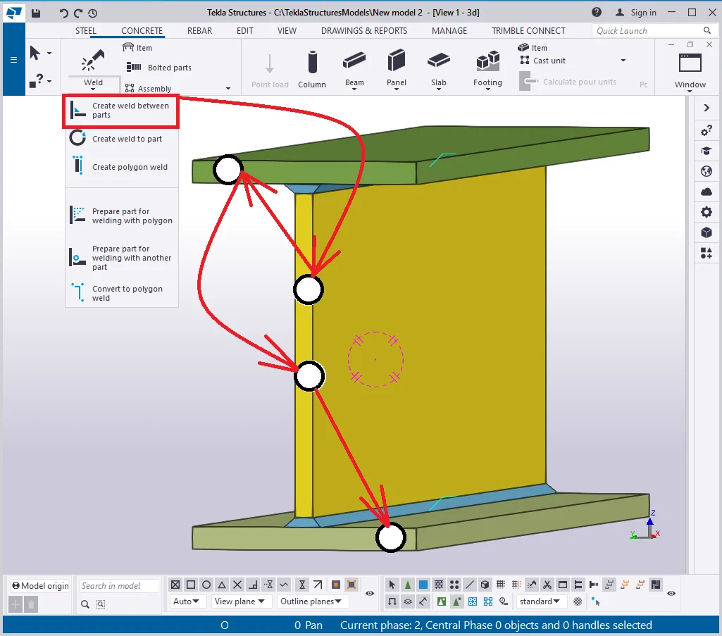
Thus we have created a beam made of rolled metal sheets. In the specification, this beam is reflected as the rolled metal, not as an I-beam. Such beams are commonly used upon a tailored object request.
Here it is essential to clarify, why during creating such a beam we were taking account of the initial beam reference line, as it should seem easier to create profiles at an arbitrary position and move them into a required position by using the Ctrl+M hotkey combination, and the latter would not be a mistake.
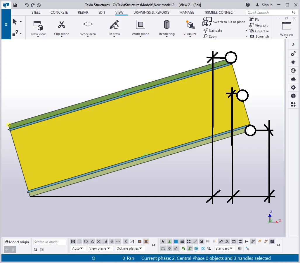
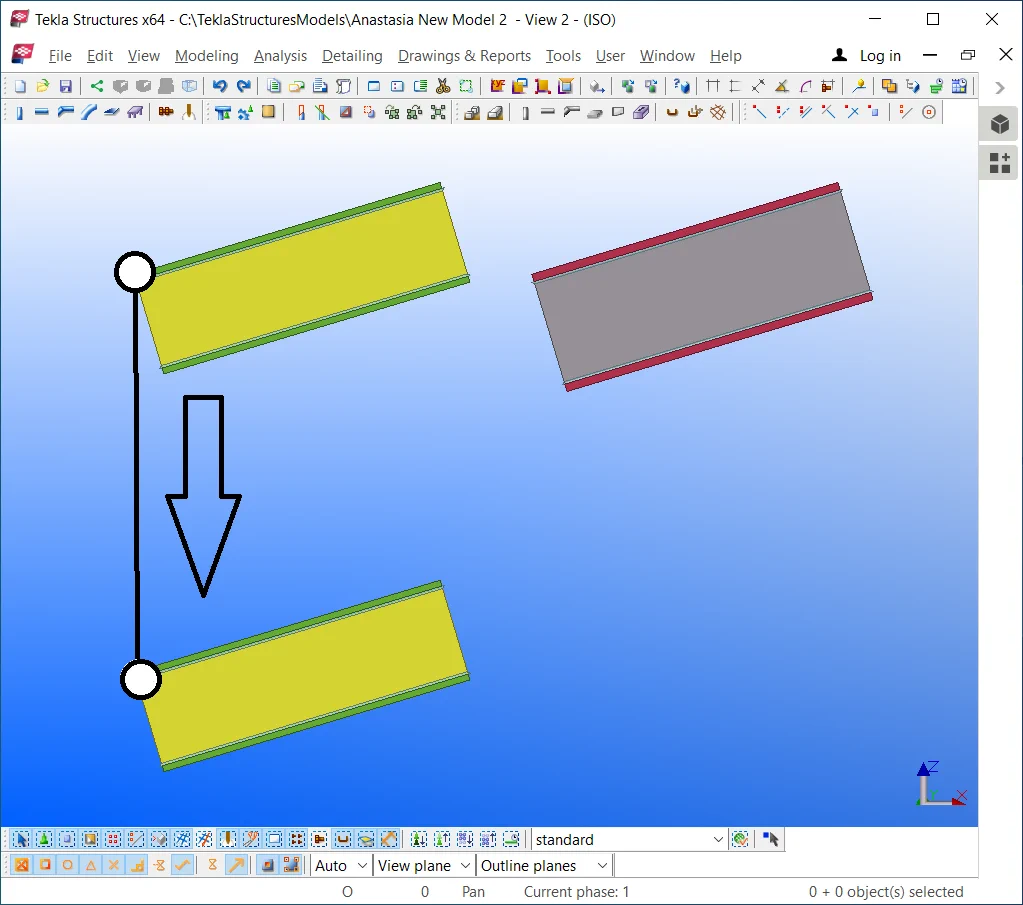
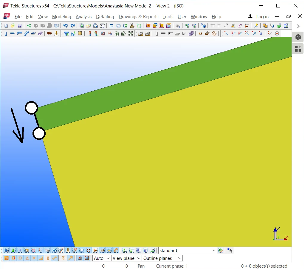
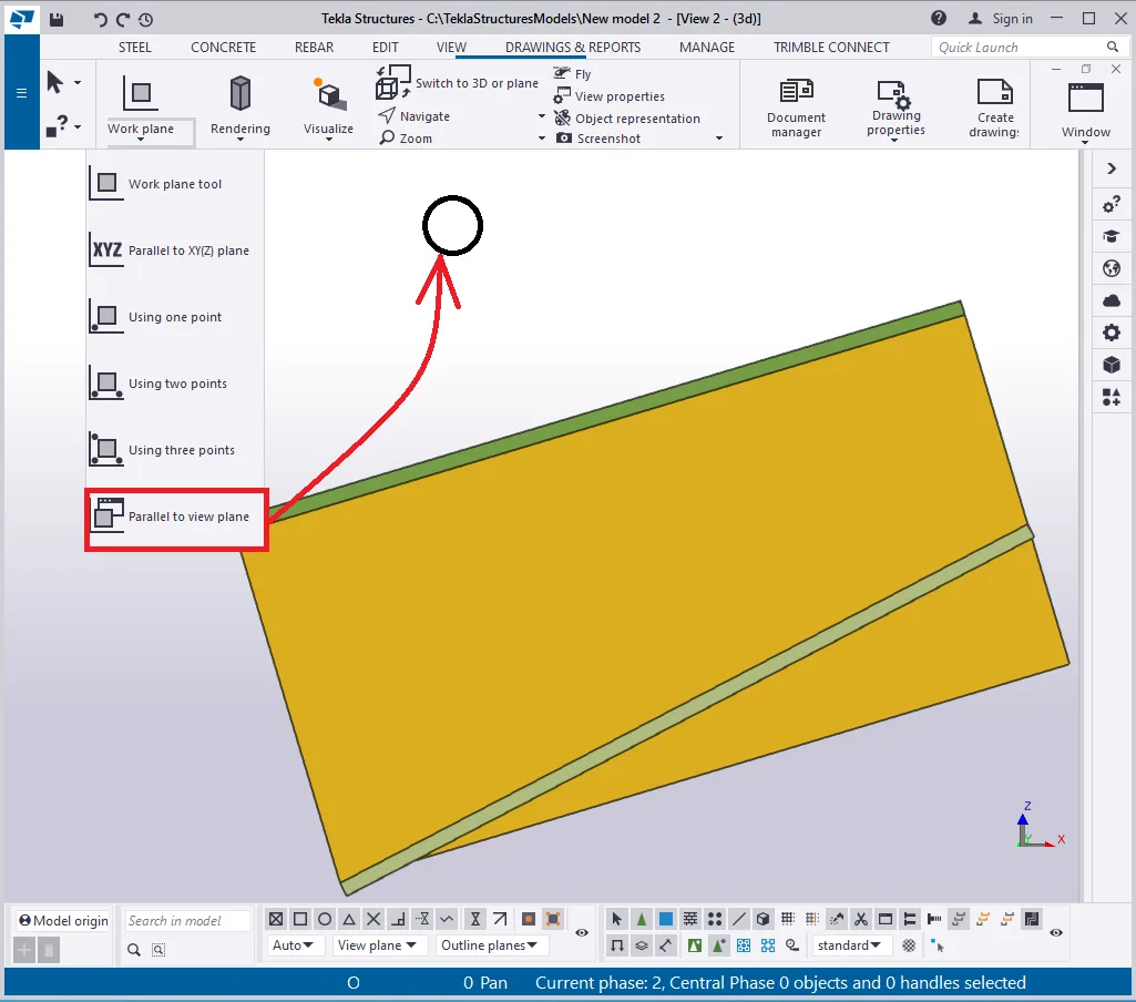
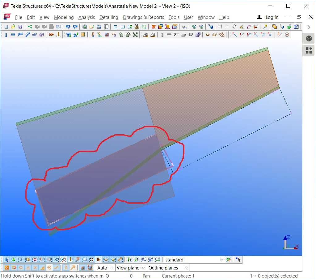
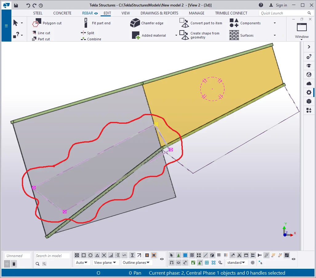
Go to the view plane by pressing the Ctrl+P hotkey combination and create
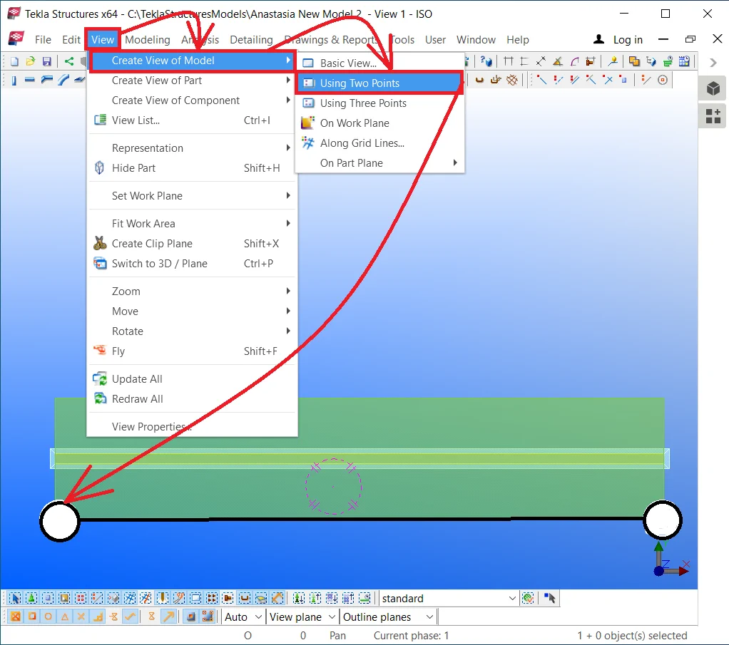
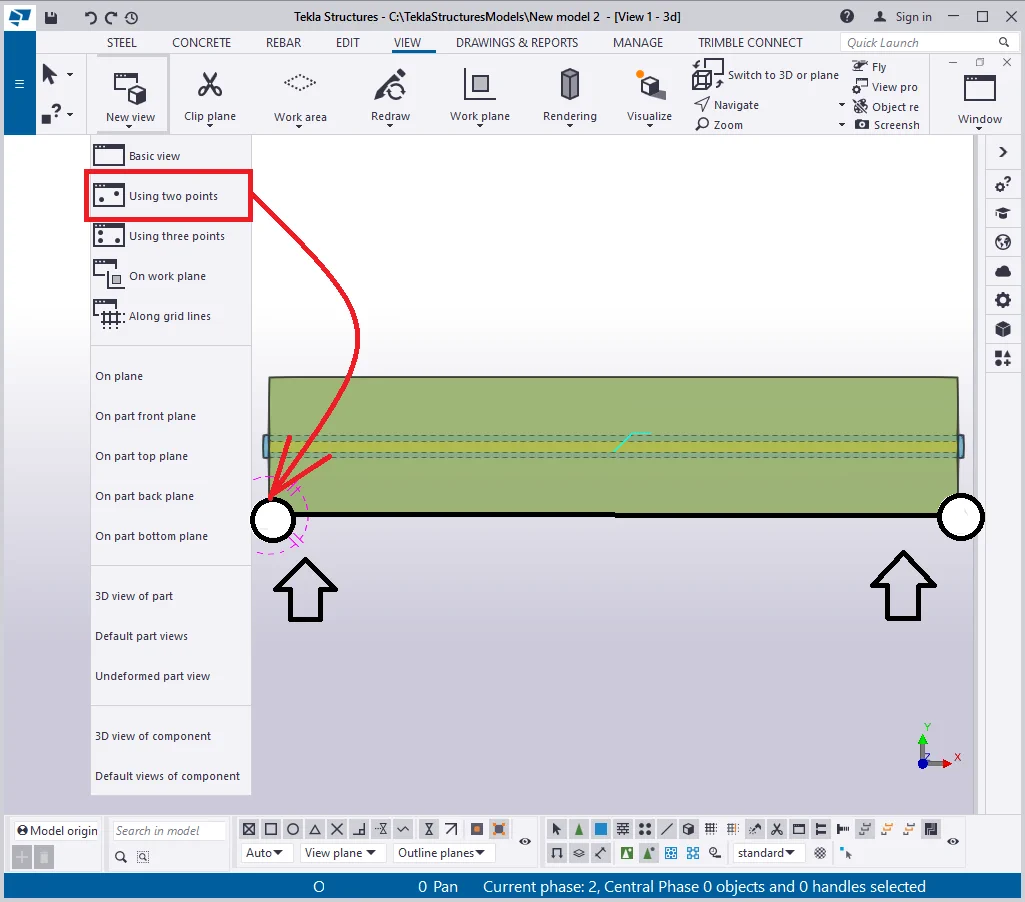
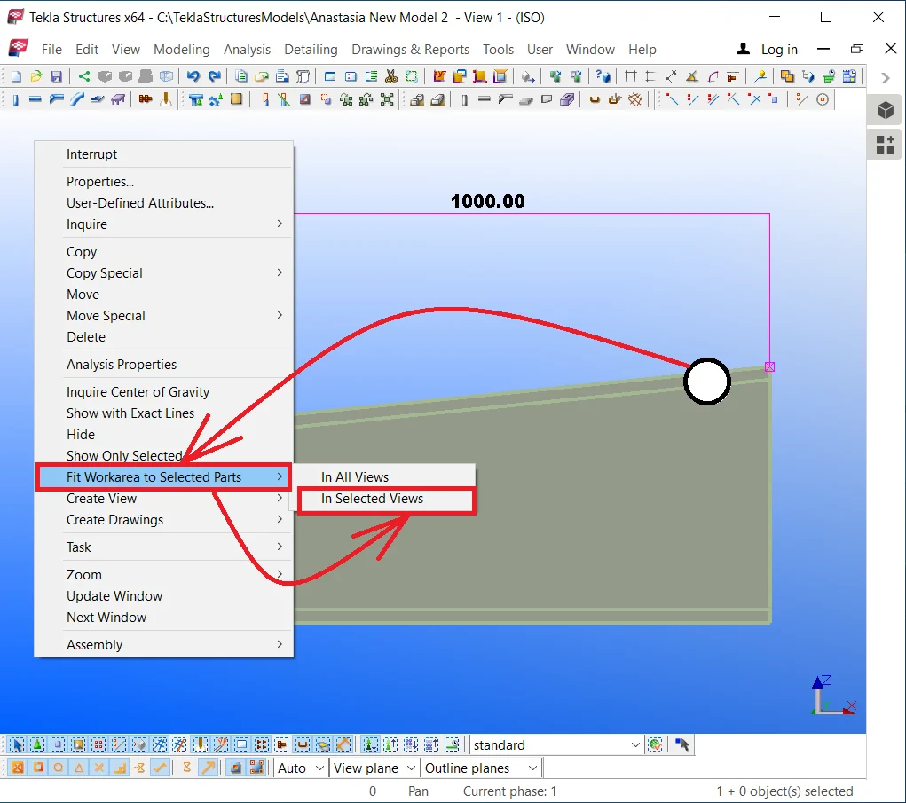
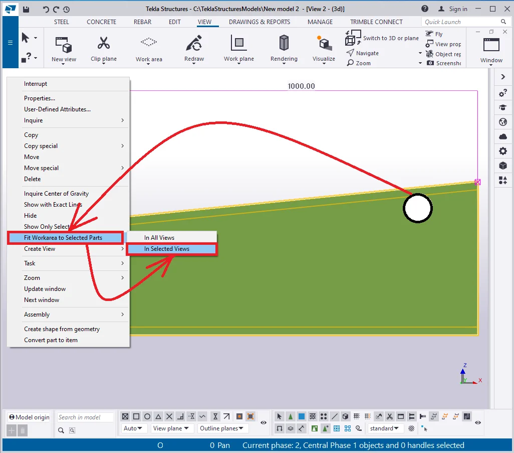
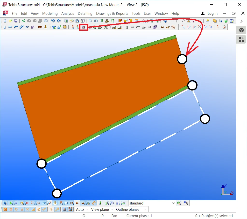
Thus we can see the "Side view" of the beam. Select all 3 components of the assembly, and by holding on the "Alt" key pressed, select three right points by framing them.
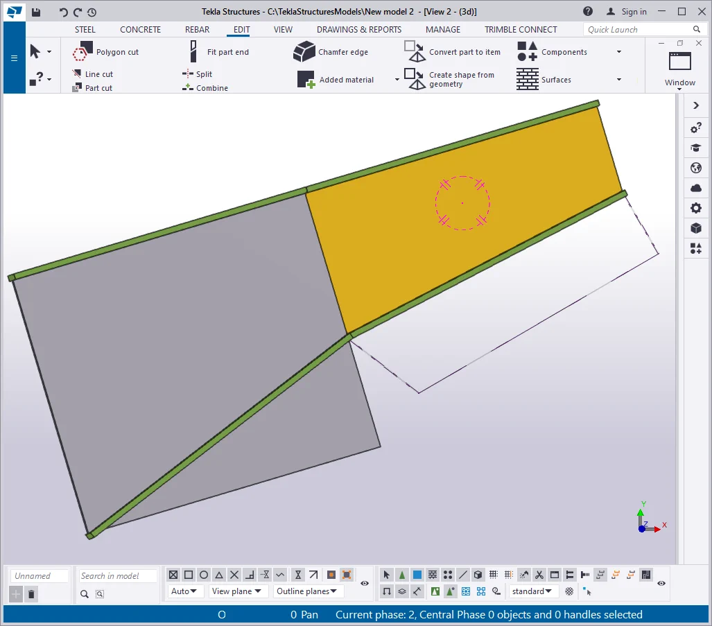
Move the points at 300 mm upwards to get a sloped beam.
Thus building up parts with the account to the reference line comes in handy, and creating a sloped beam does not require using the “Rotate” tool.

If we would not take account of the reference line of the initial part when creating the other assembly components, we would be supposed to adjust each part separately or to use the “Rotate“ tool.

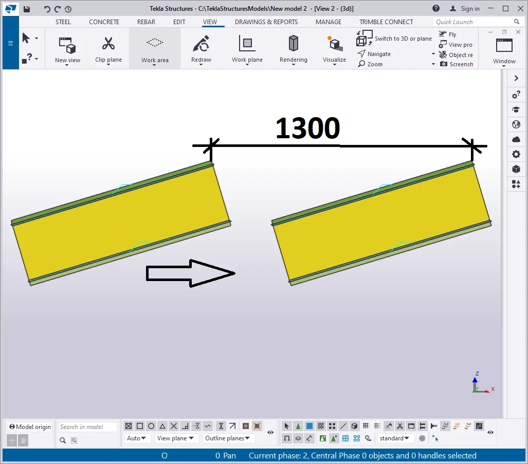
During modeling a project, there can be used various beams, composed of the rolled metal sheets. It is of no use creating a new profile, as it is enough to copy the one already created and configure its profile values as required. Copy the sloped beam to the right at 1300 mm.
Note that welds are copied automatically along with the beam.

Set out different thickness and plate width values, by configuring the plate profile to “—25*300”. Change its class to 9 for a better visual representation.


Modify the profile of the beam's wall to “—20*350”

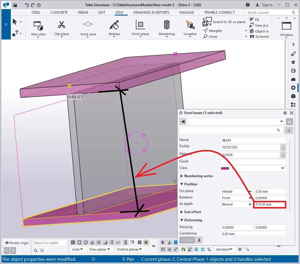
Let’s set up the offset values of the plate taking into account

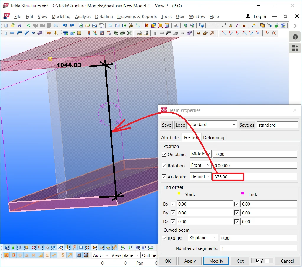
Proceed to configure the bottom flange plate according to the respective characteristics of the upper flange, and indicate the offset value equal to the beam's wall height+ the upper flange thickness sum of values: 350+25=375.
Thus during modeling, it is possible to create various welded uniform cross-section beams, multiply them by copying and configure them as required.


The algorithm for modeling a welded non-uniform cross-section beam in
TS differs from the respective for welded uniform cross-section beam by
not taking into account the reference line of the profile.
The reason is that non-uniform beams are of seldom use and their slope angle in the majority of cases coincides with the respective angle of the roofing and walls. That is why there is no need to rotate (slope) them, but it will be more convenient to modify them with the above reference line position.
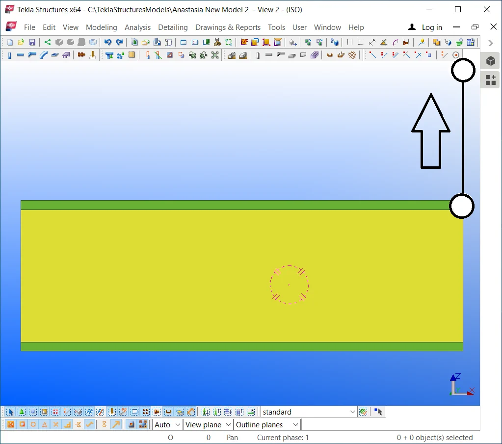
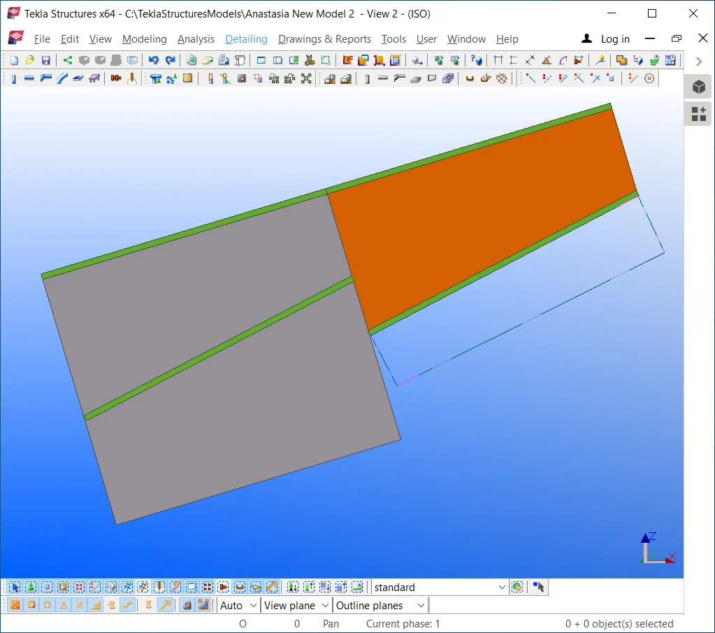
Copy the beam from the previous exercise downwards at 1300 mm.
Select the beam wall and set out its “At depth” value according
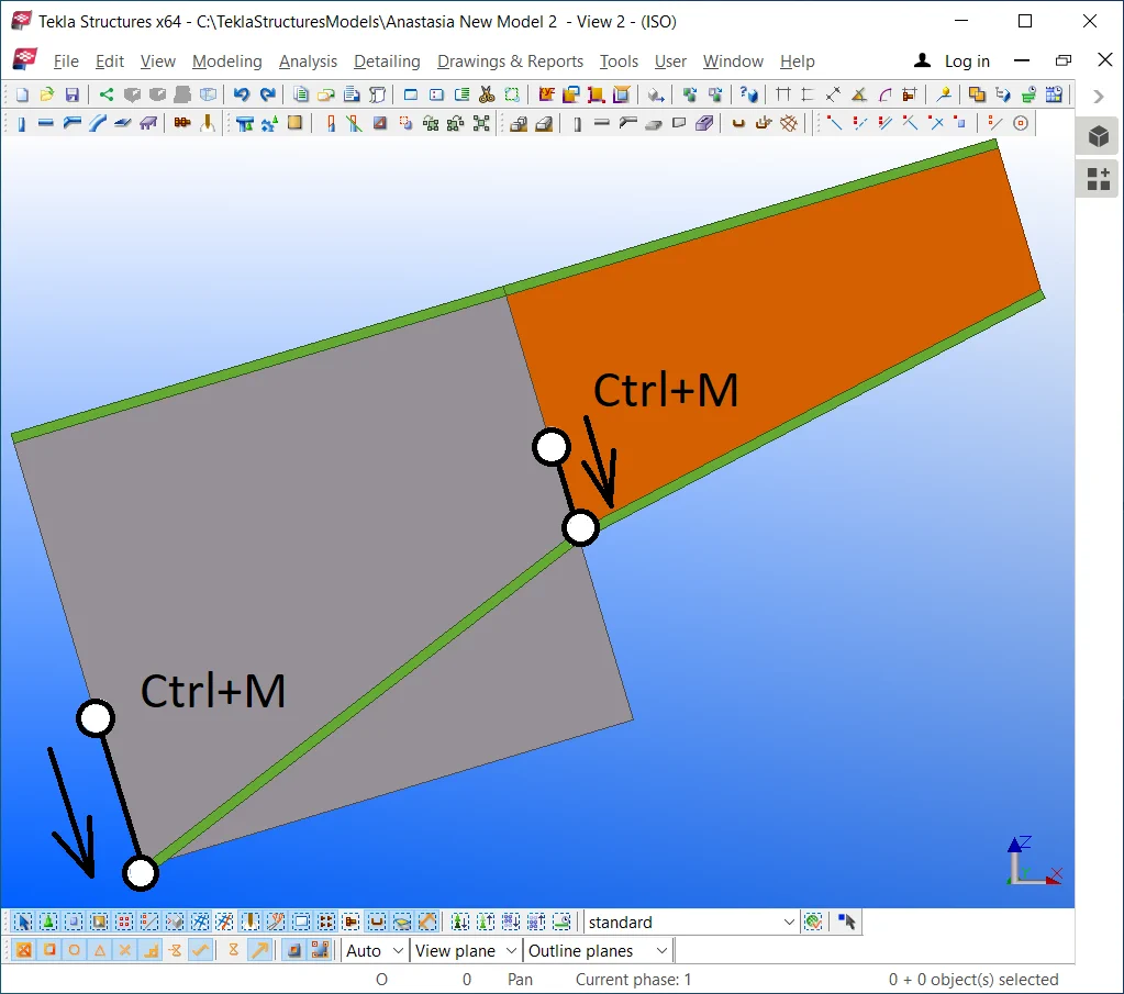
Move the beam's wall downwards in the way its flange gets laid at
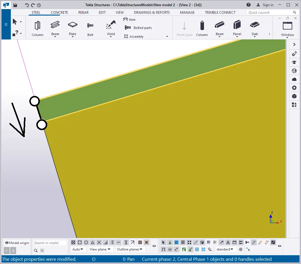
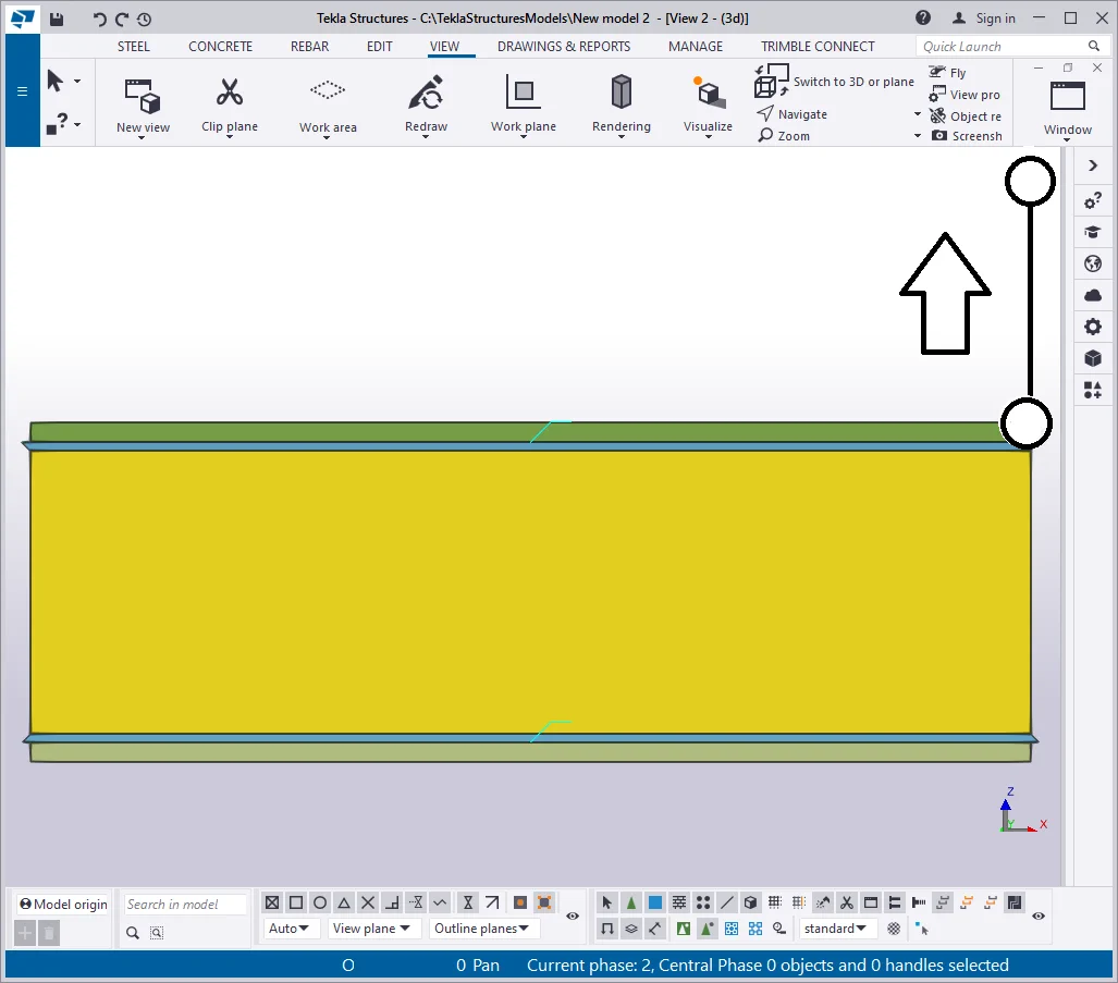
Proceed to set to null the bottom beam's flange offset value. Thus

Move the bottom flange to the required position without recurring to setting
Thus we have created a uniform cross-section beam with different reference
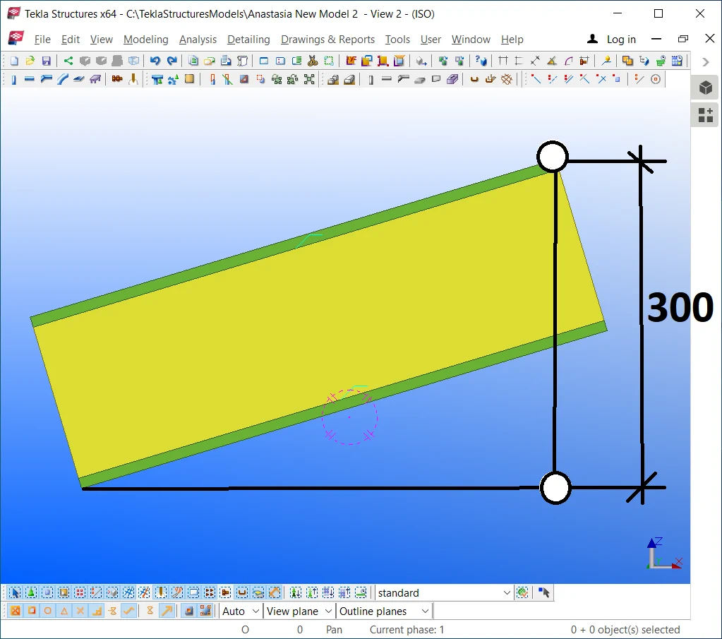
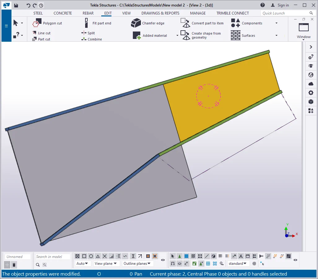
Maximize the height value of the beam's wall at 200 mm by changing its profile to “—20*500”. Modify the beam's wall class value to 13 for a better visual distinction.
Click on the bottom flange and select its left point. Move the point as

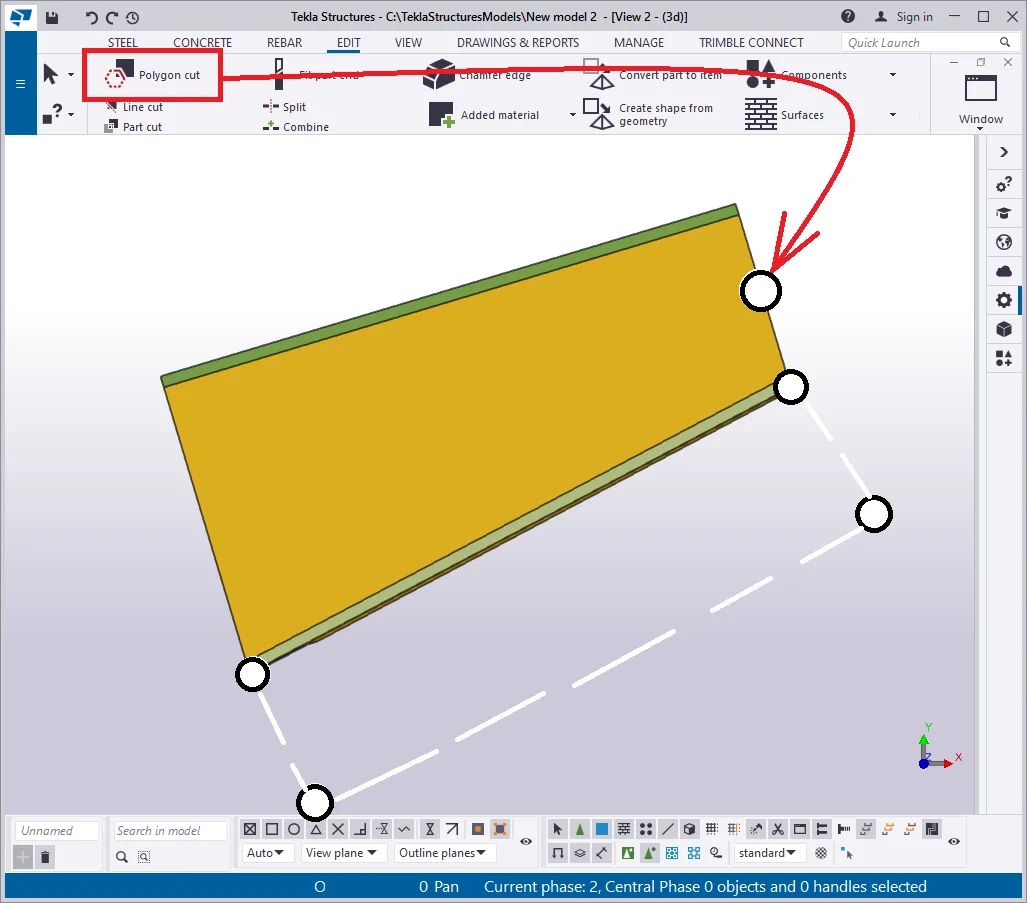
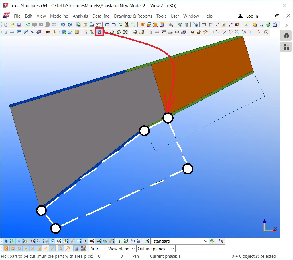
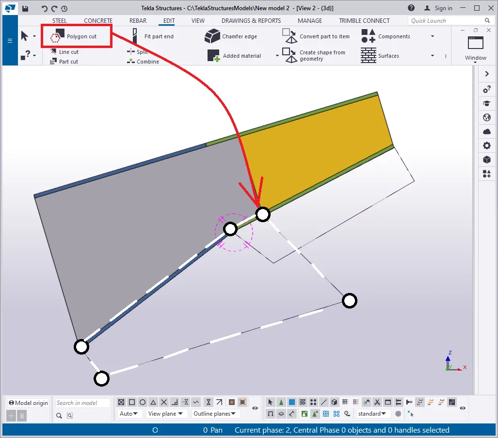
Execute the polygon cut. Prior to this, make sure that the Z-axis is perpendicular
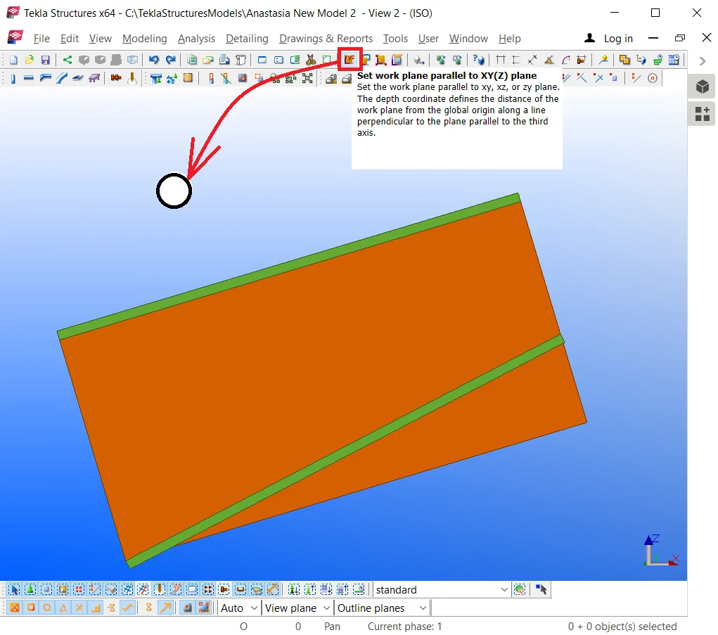
Execute the “Polygon cut” in the way the resulting added material
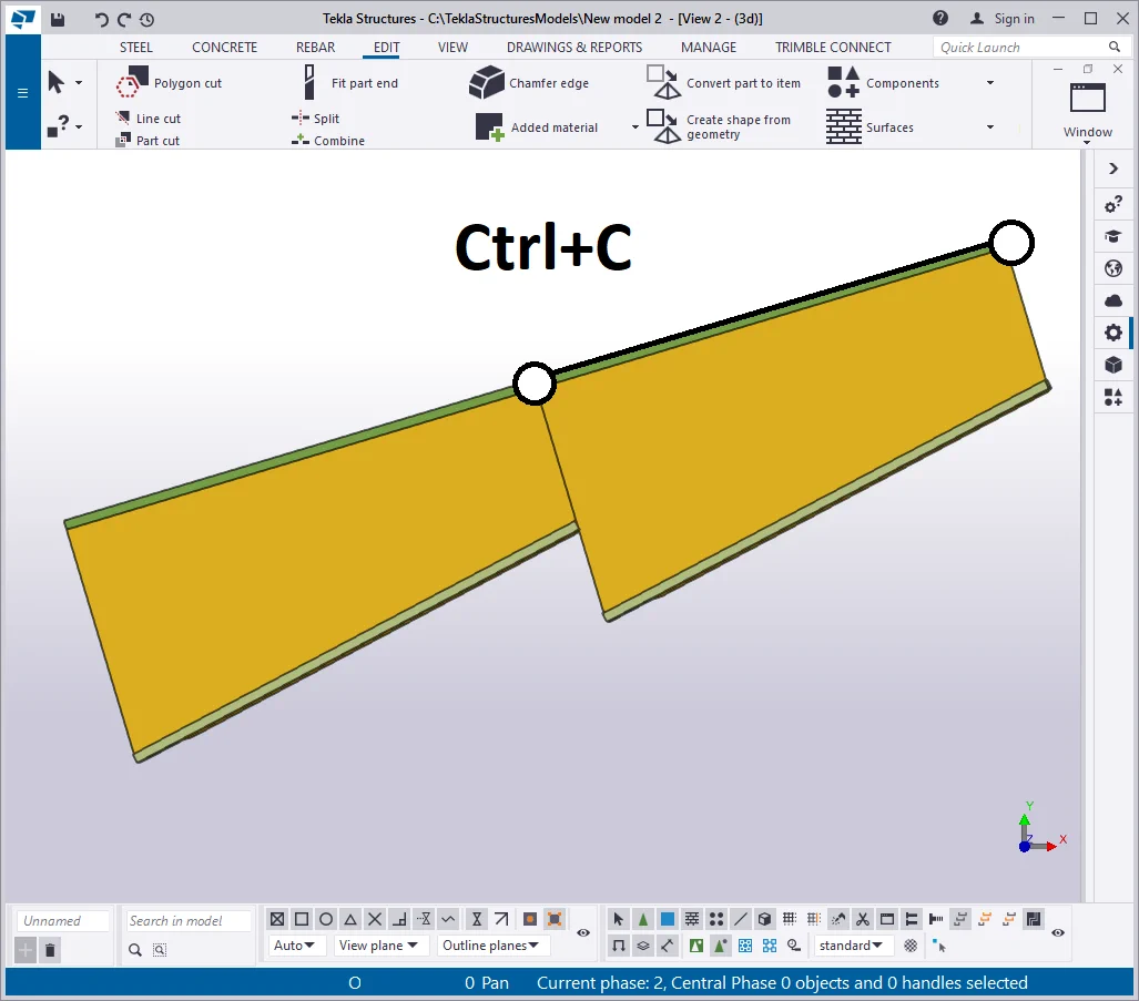
Copy/Paste the beam to the left by using the Ctrl+C hotkey combination.

Modify the profile of the copied beam's wall to “—30*900”.

Move the bottom flange points as it is shown below:
Note that the added material object does not work anymore, as its initial
Go to the added material properties window and configure its thickness
Delete the added material plate and create a new one.

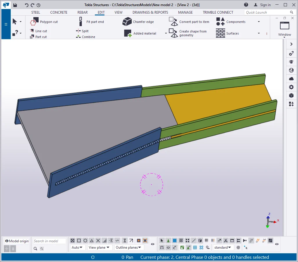
To avoid allocating in a line the welded seams of the beam flanges and

Modify the width parameter of the right beam flange at “—20*250”,
Create a polygon cut, where 3 points are located at the outer face bottom
Thus we have created a non uniform cross section beam, defined by various
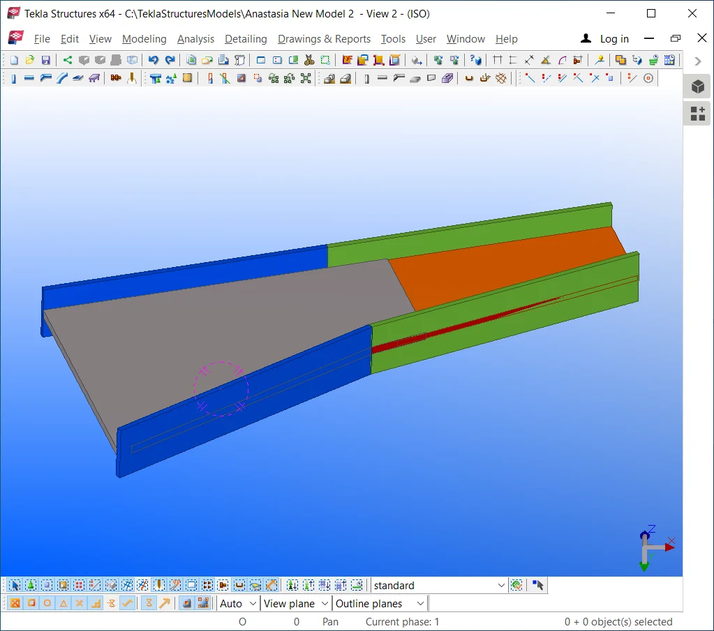
Weld on the parts by yourself by using an arbitrary welding chord size.

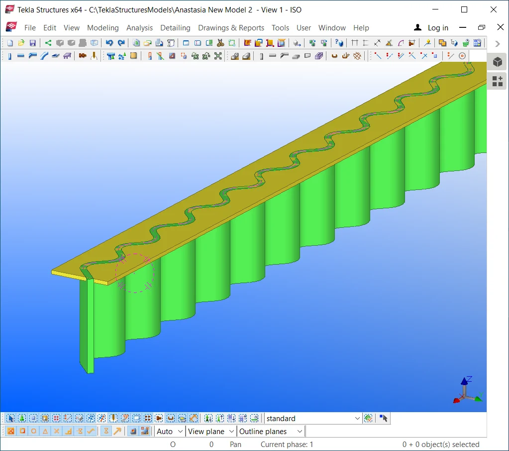
These are special beam-type frequently used in construction.
Create such a beam type using the Tekla Structures software.
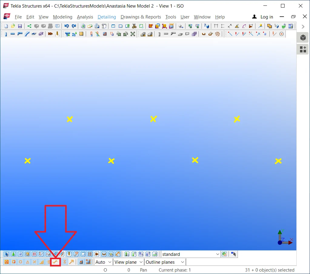
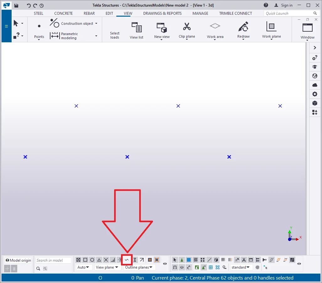
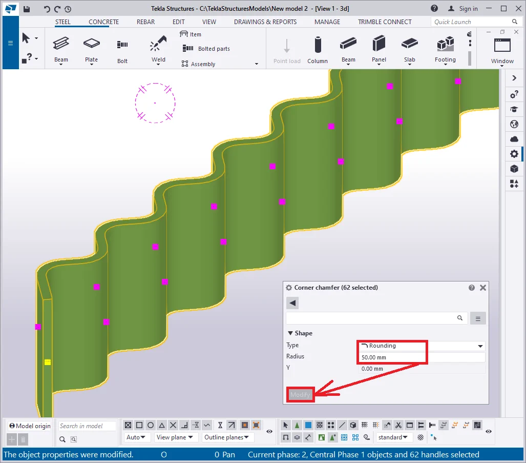
Go to the "Top view". By using the construction geometry tools,


Switch off the “Snap to any position” tool to avoid missing
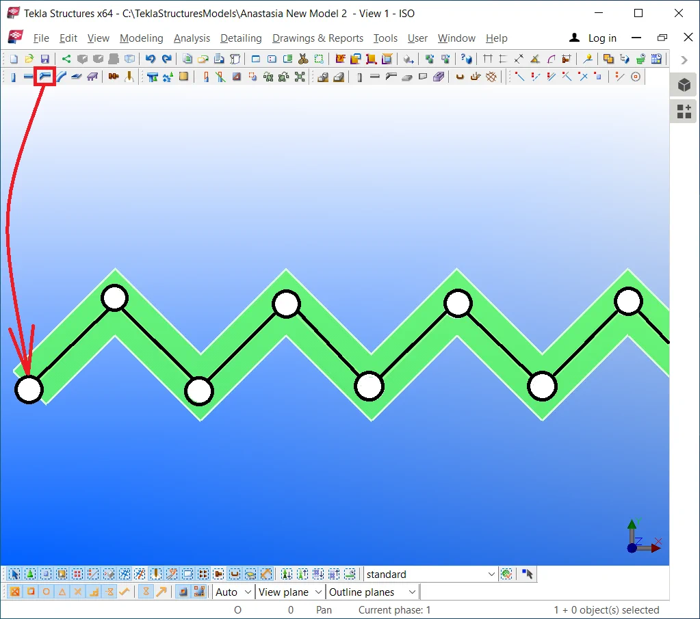
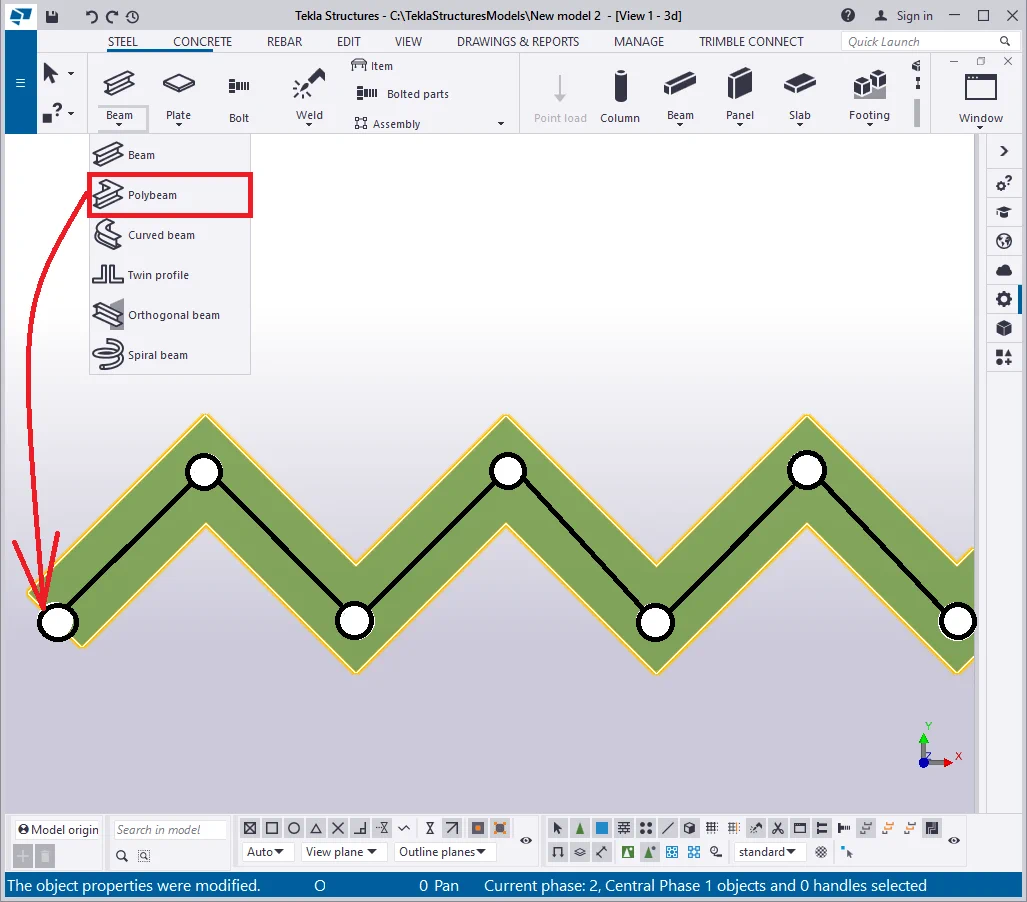
By means of the “Polybeam” tool, let’s trace a beam, passing through all the 62 points. Upon completion, do not forget to press the mouse wheel button or the “Space” key to finalize the operation.
It is important to mention that such a type of beam has several limitations: its width shall not exceed its length value. Let’s check out the situation when the width profile value is admittedly large enough.
Switch the profile value of polybeam to the rolled metal with dimensions
As you can see from the above, it is not possible to create a polybeam of such a geometry. The software renders the polybeam as a thin line, denoting there is a must to change the profile settings.
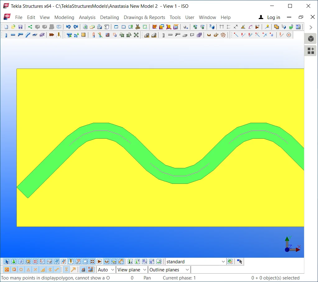
Set out the profile type to a reasonable value as “—20*300”.
If still the profile geometry is shown as erroneous one, then there is a need to set out the “Rotation” parameter value by turning it at 90 degrees, as now the profile is of 300 mm thickness.

Toggle between the values of the“Rotation” field to get a clear understanding of the typical geometry error and the factors causing it. Depending on the current view settings, the “Rotation” field values might work in different ways.
Execute the configuring by yourself.
Compare your results to the below:

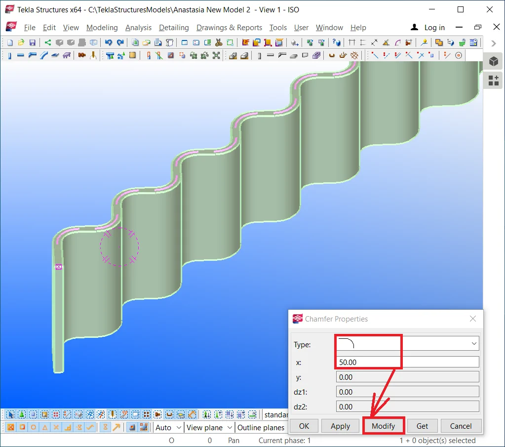
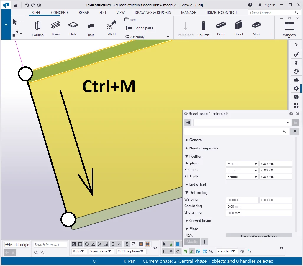
Shift the I-beam at 50 mm in the upwards direction by using the Ctrl+M
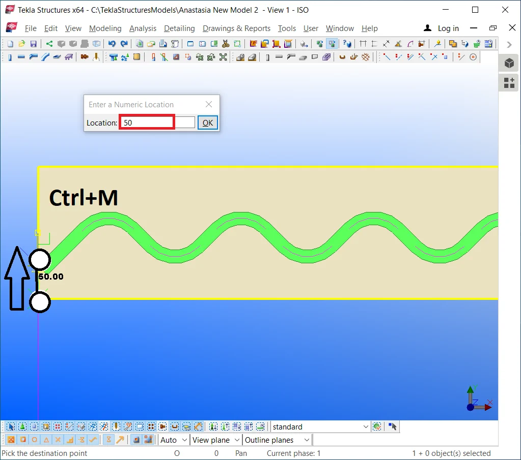
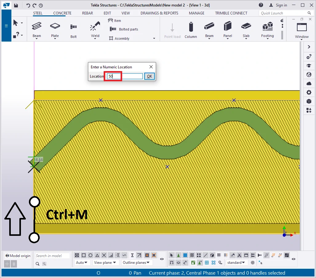
Now, the polybeam flange is located right at the profile center.
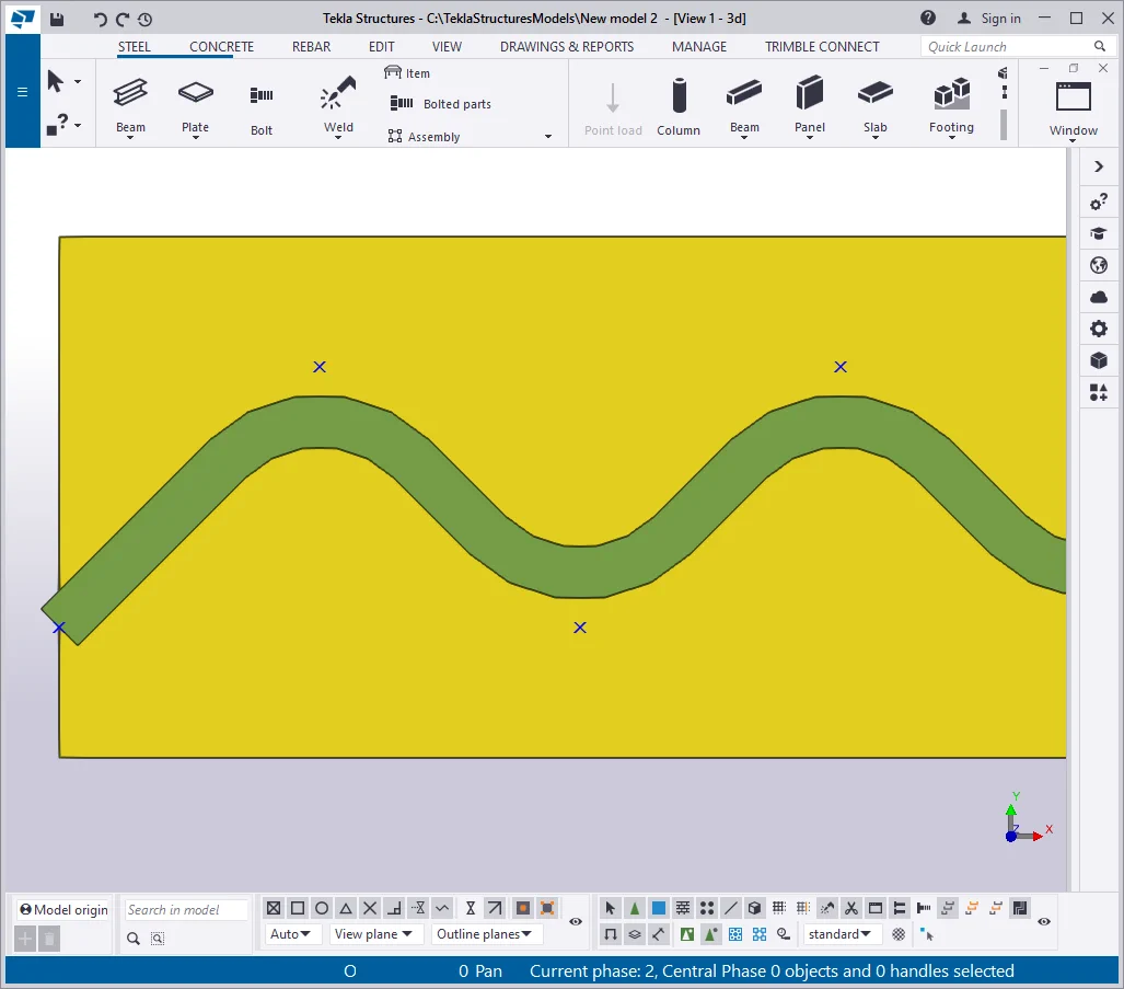
Rotate the view in the way to see the beam's wall and flange in 3D. It comes evident that the profile of the beam wall has no vertical offset.
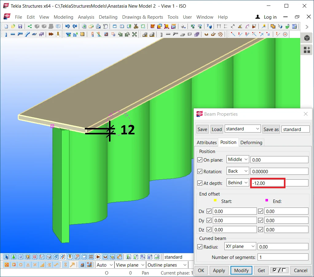
Go to the "Polybeam properties" menu and indicate the offset value equal to the profile thickness according to the scheme of a straight line beam with a common reference line. See below:
Set the offset value equal to 12 mm.
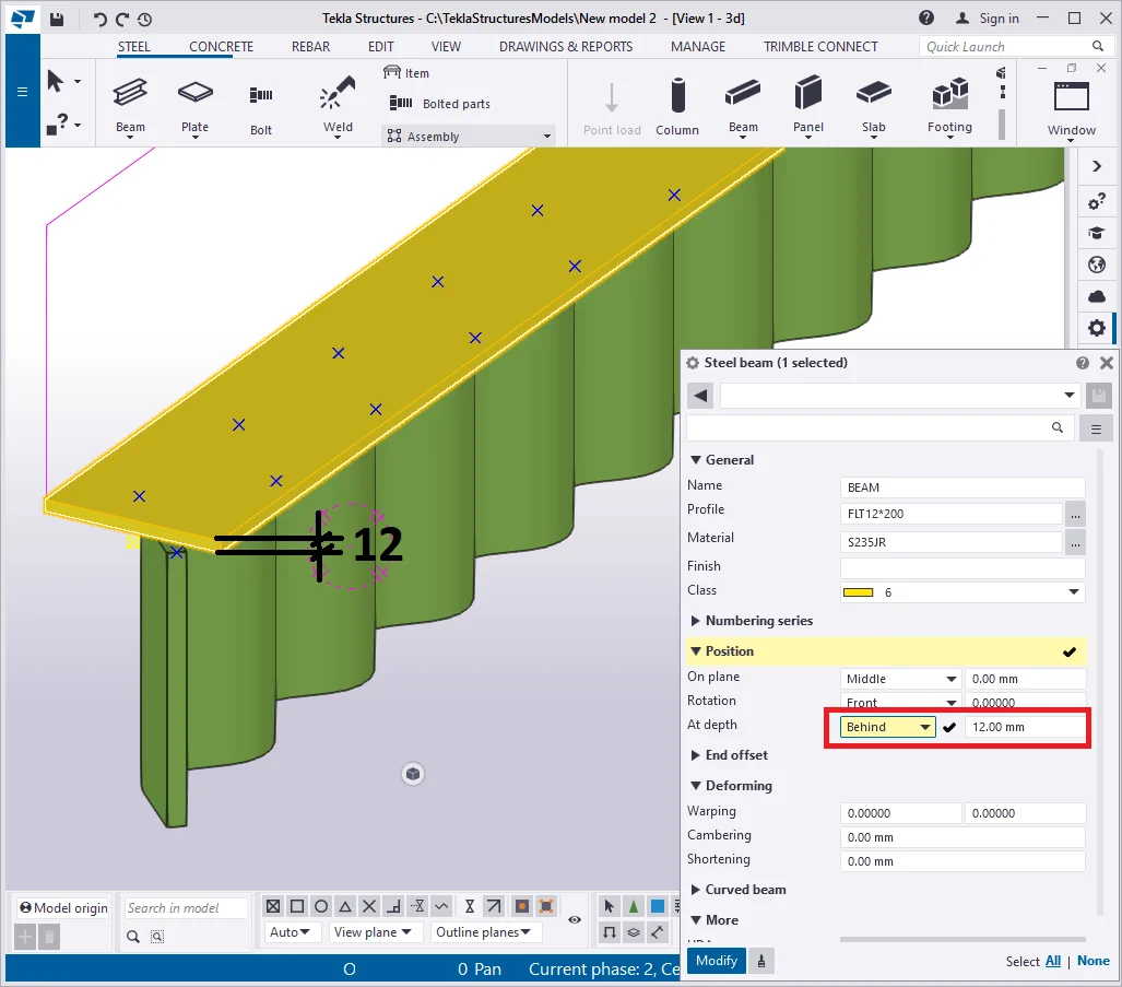
Copy the top plate over the initial plate position and configure its offset

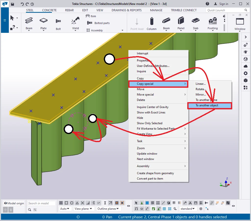
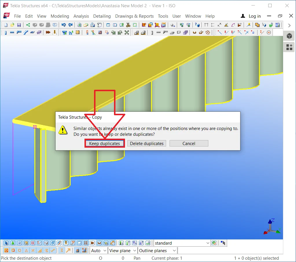
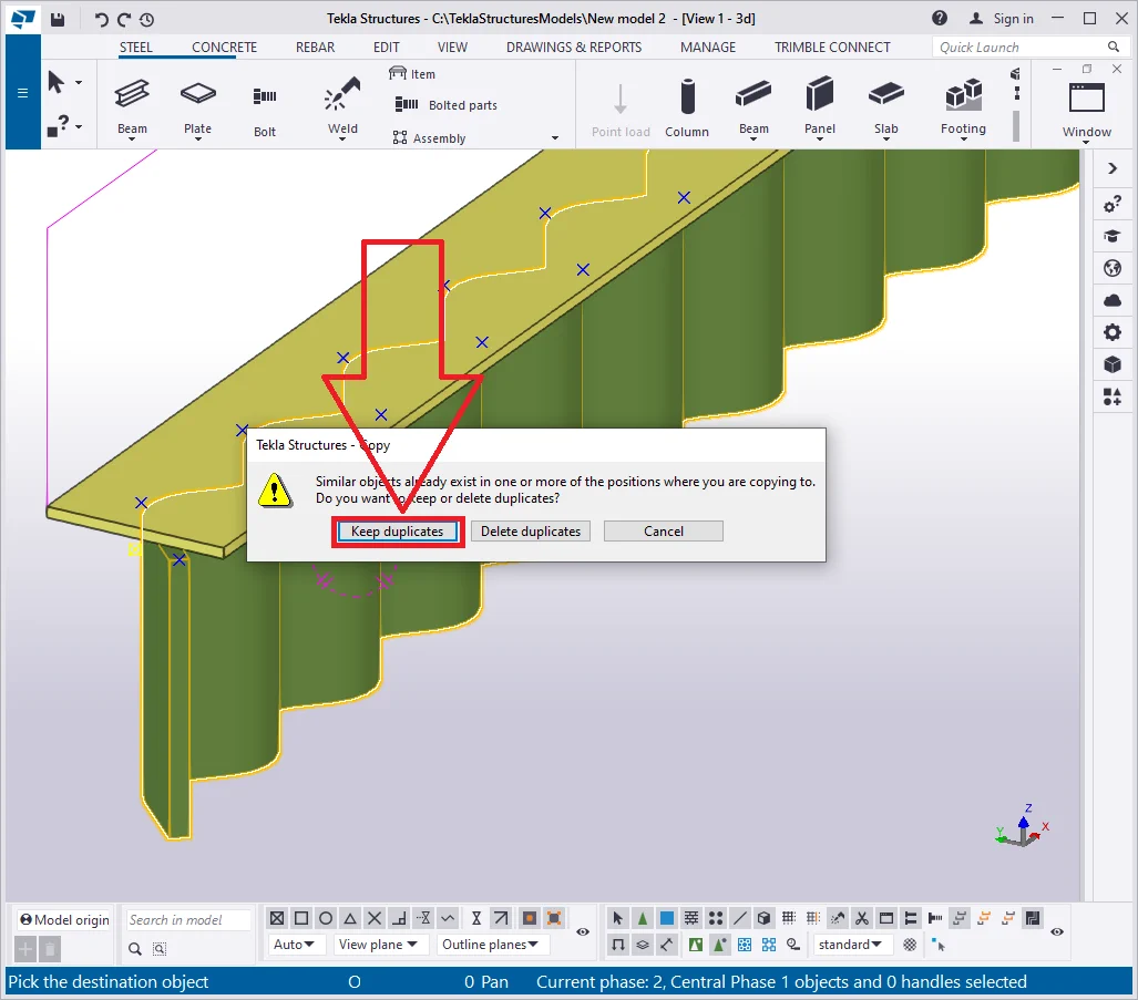
Upon executing the above, the TS will pop up an alert message about the duplicates created, as the duplicates are causing doubling the weight of the model and drawings overlapping.
Confirm creating duplicates by pressing the “Keep duplicates”

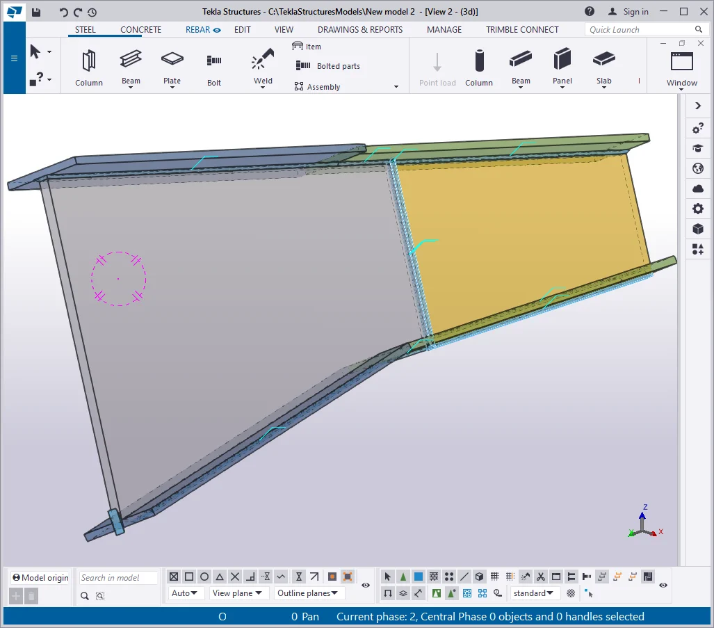
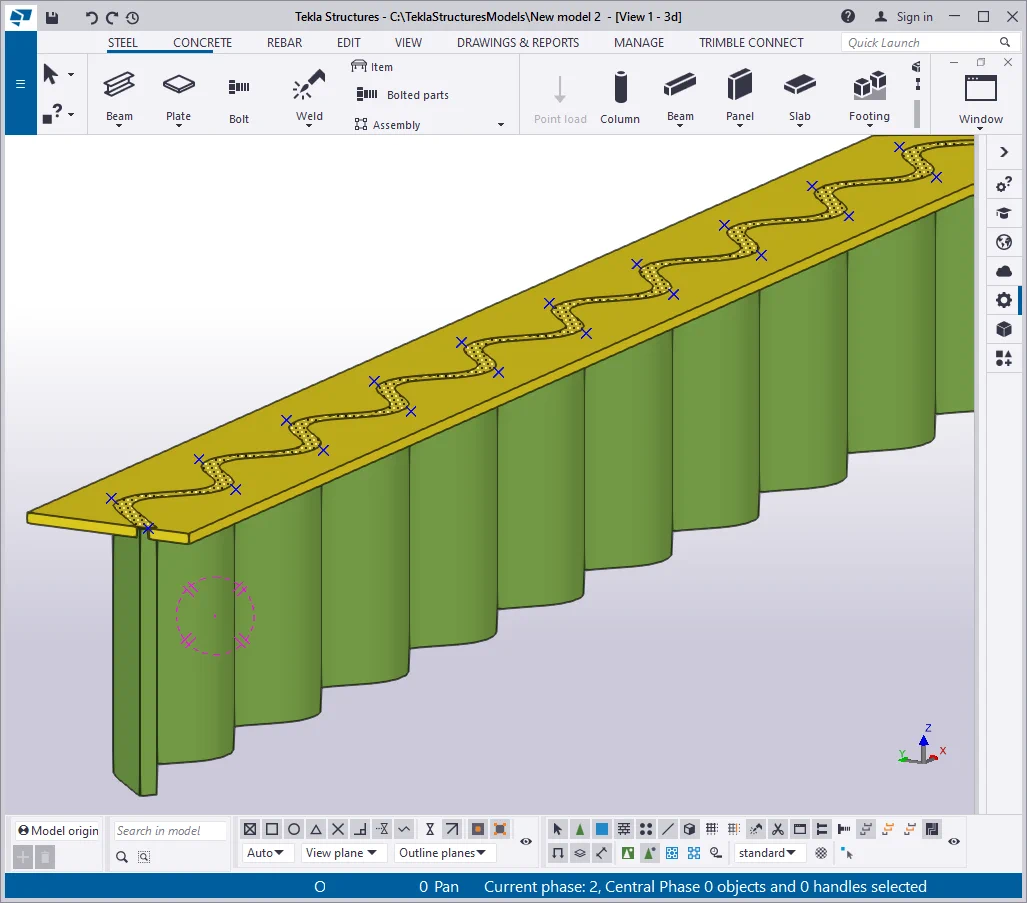
The only step left to be done is welding on the parts. Indicate the I-beam
Note that in the current case, only the “Around” type
Thus we have created a SIN beam. Other such beams when running a project