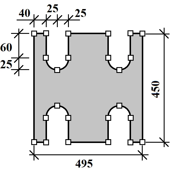
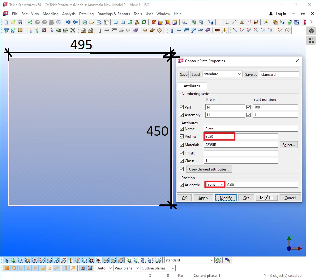
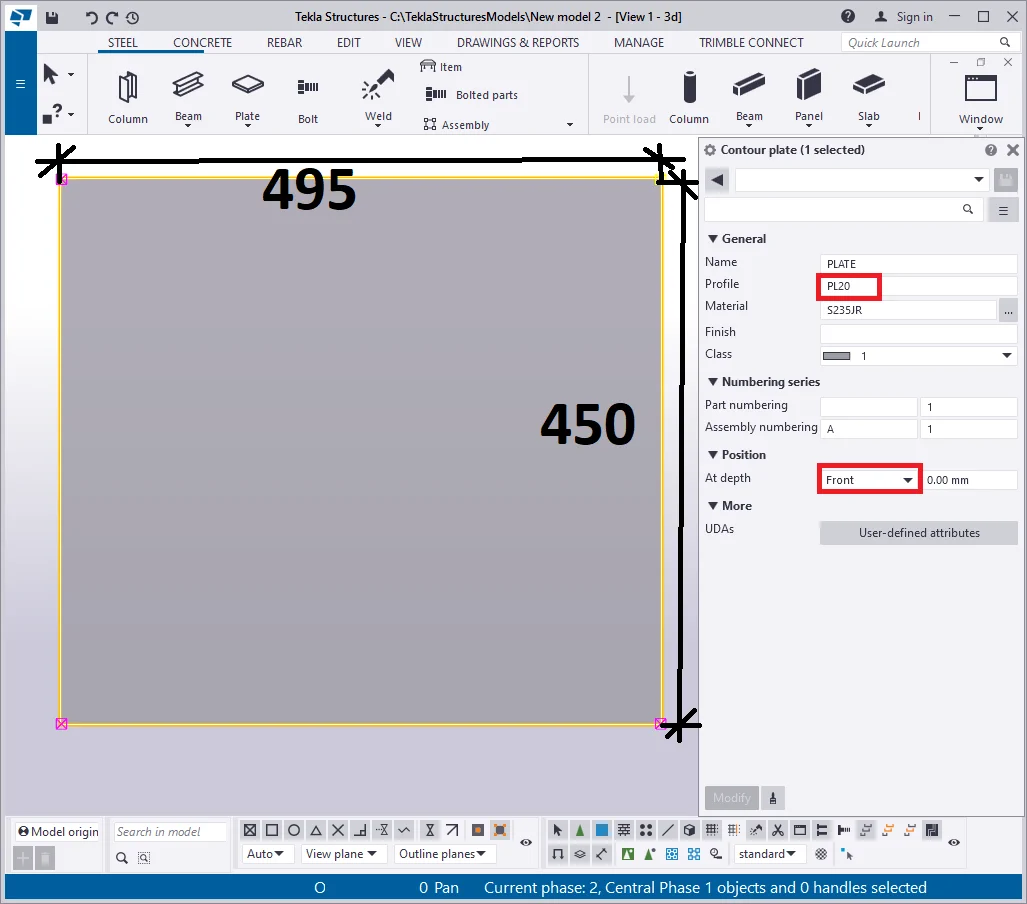
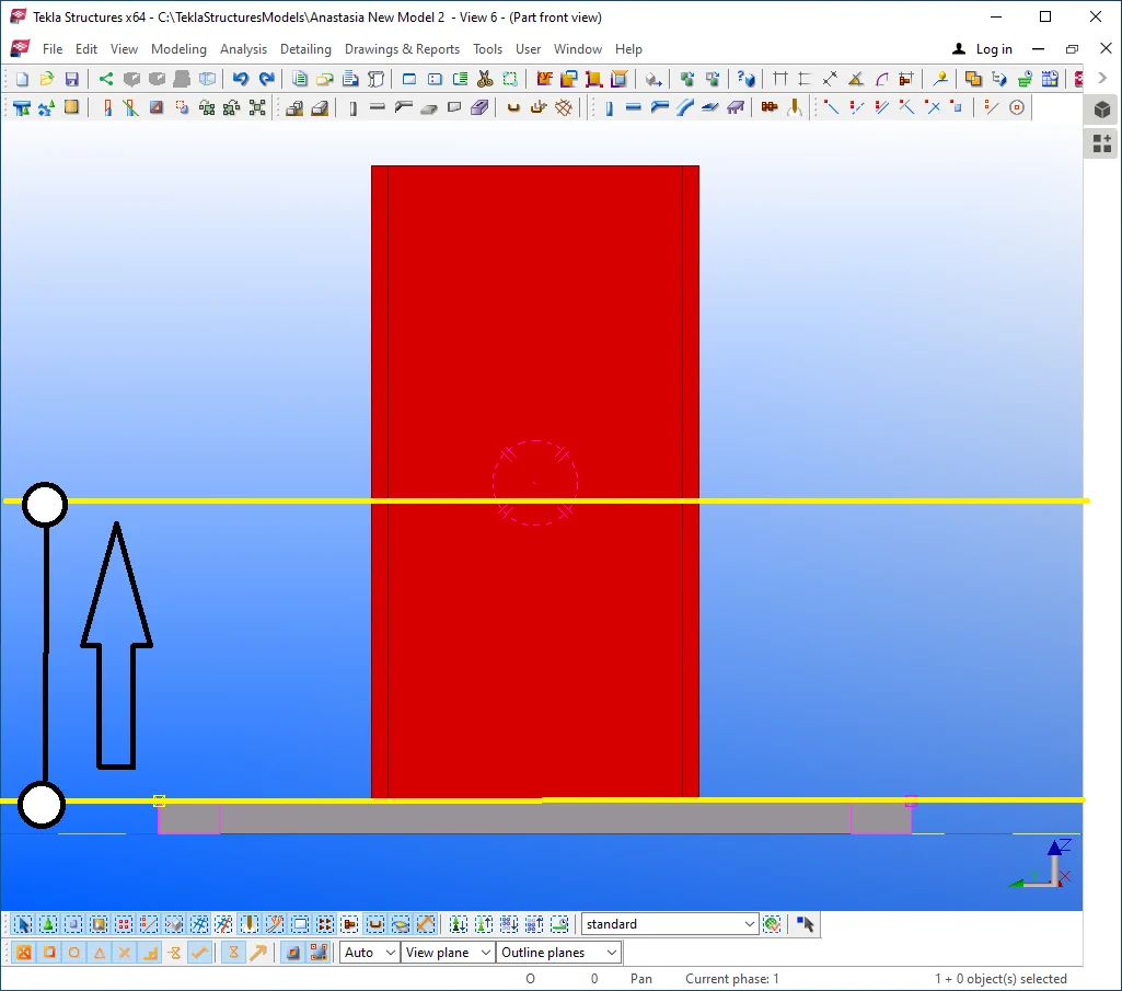
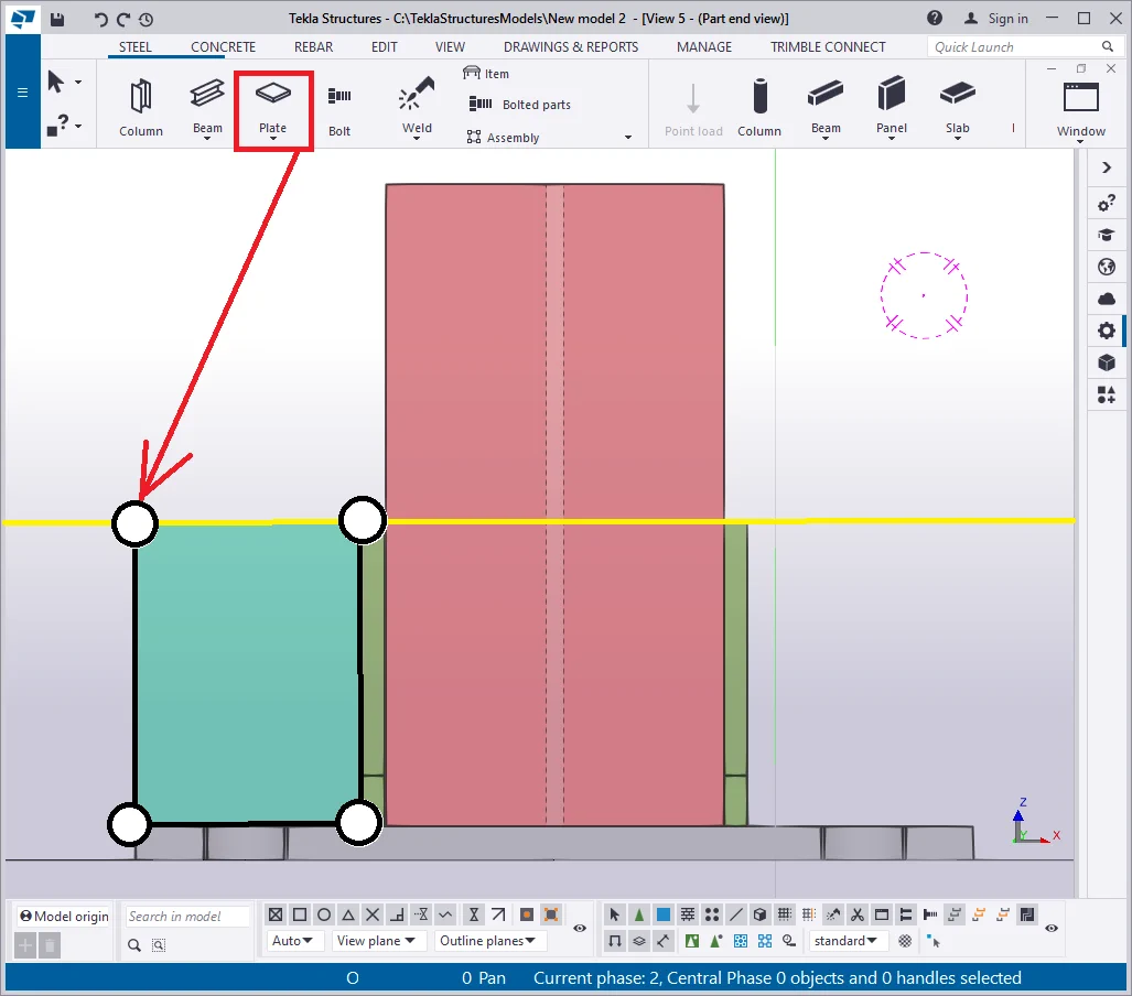
Create a plate with dimensions of 495 x 450 mm, a thickness of 20
|
|
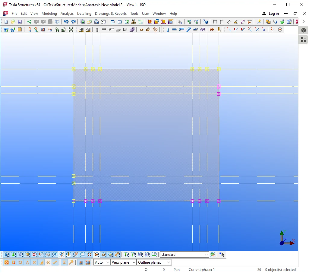
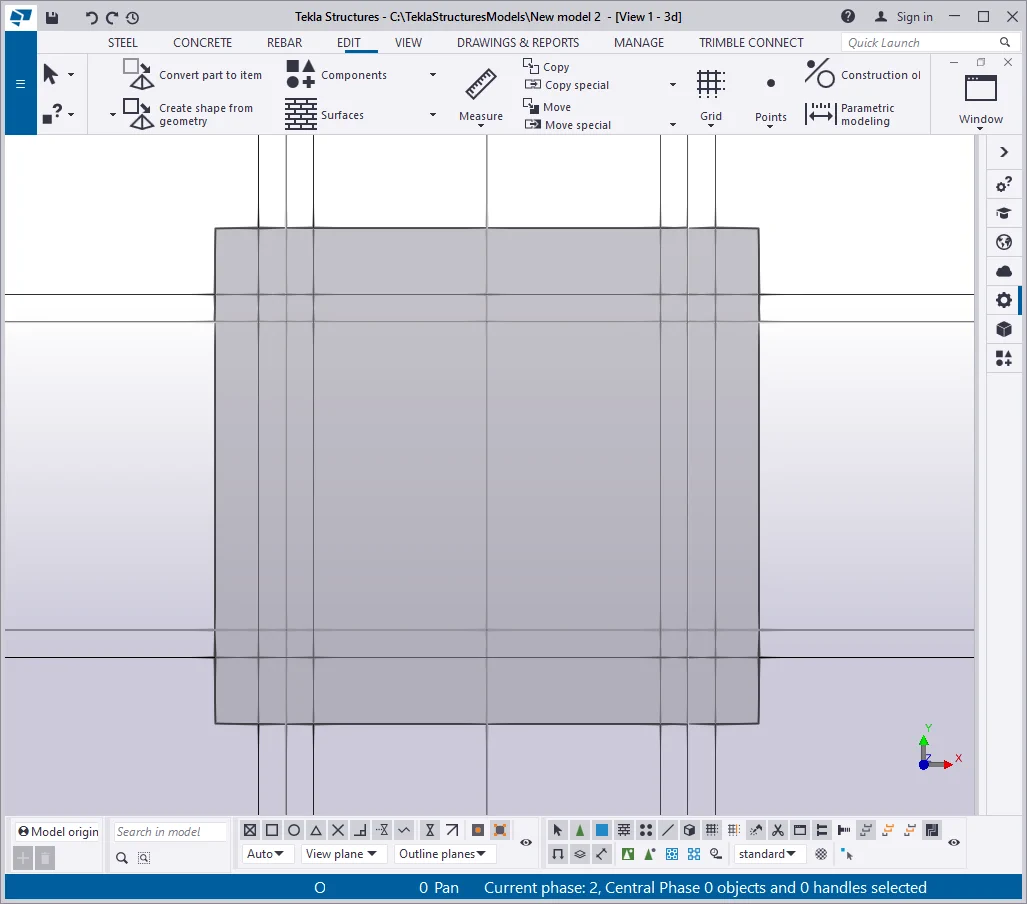
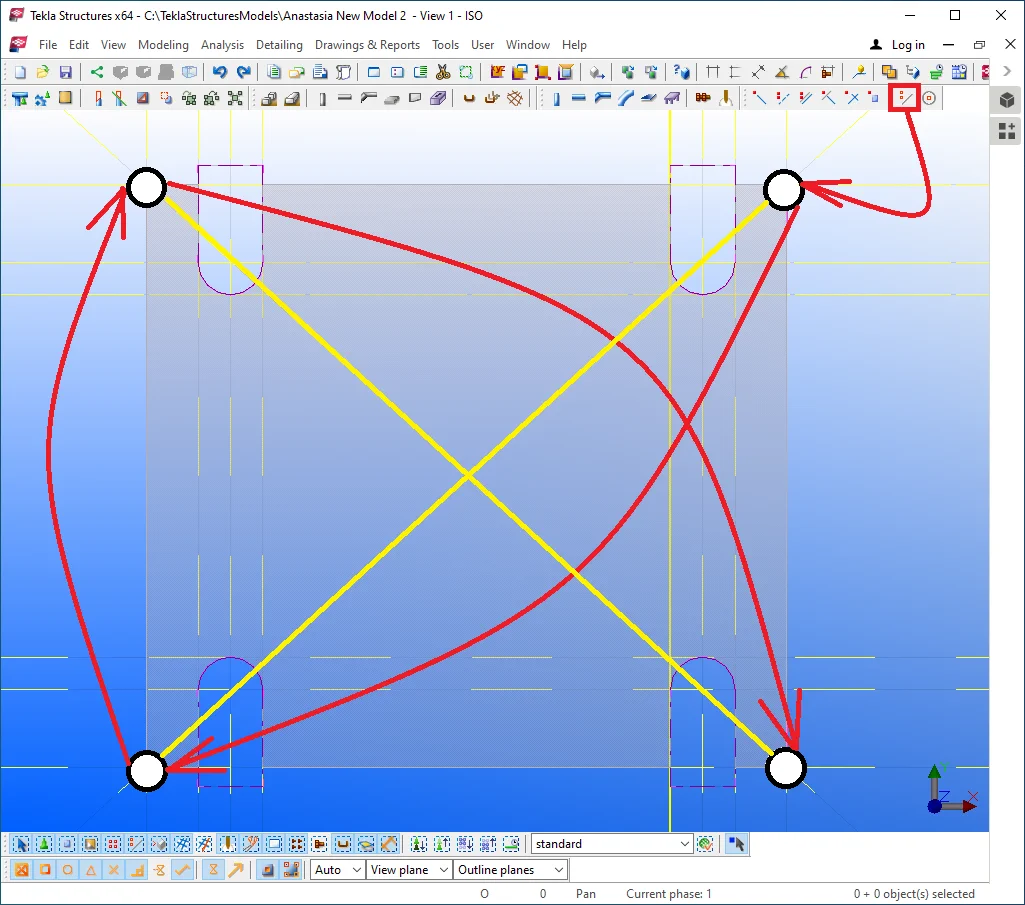
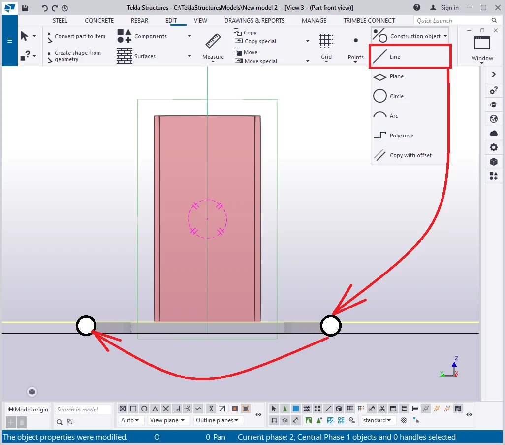
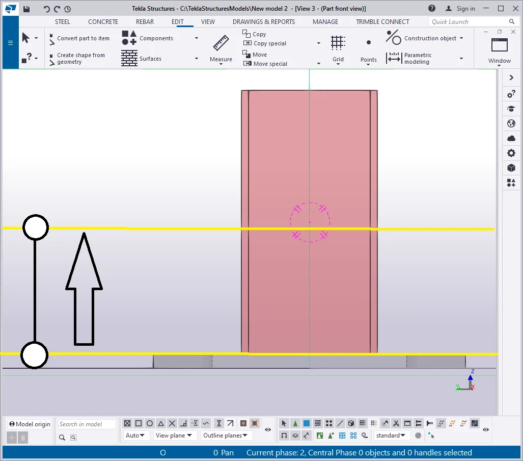
Creating such a geometry requires using the construction geometry objects to correctly set out the cuts. Thus firstly create vertical lines and copy them accordingly to the below scheme. Proceed the same way to the horizontal lines.
|
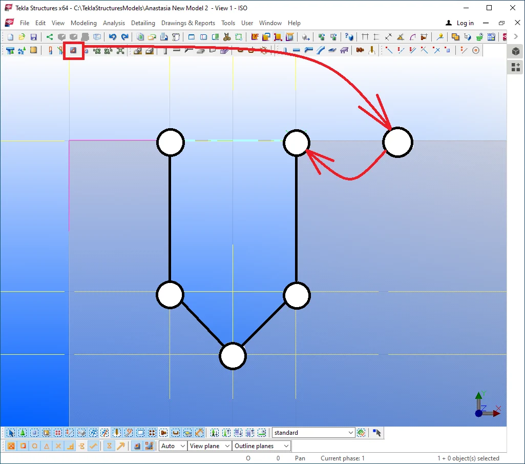
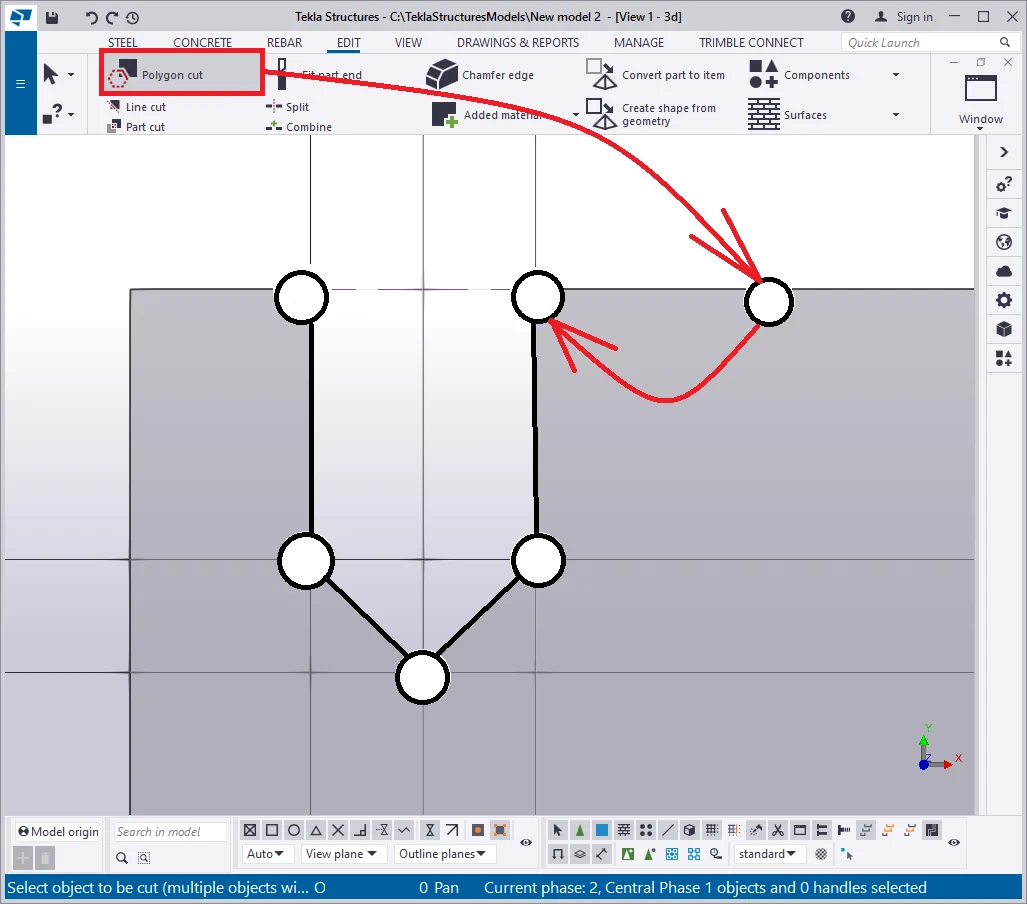
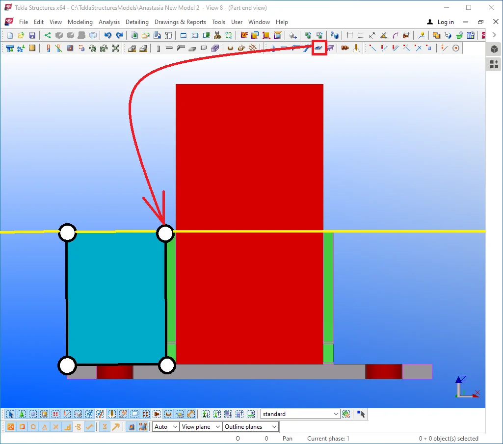
We have already exercised creating cuts in the previous chapter by creating a plate and adding points to it. This time wll exercise another method, by applying the “Polygon cut” tool.
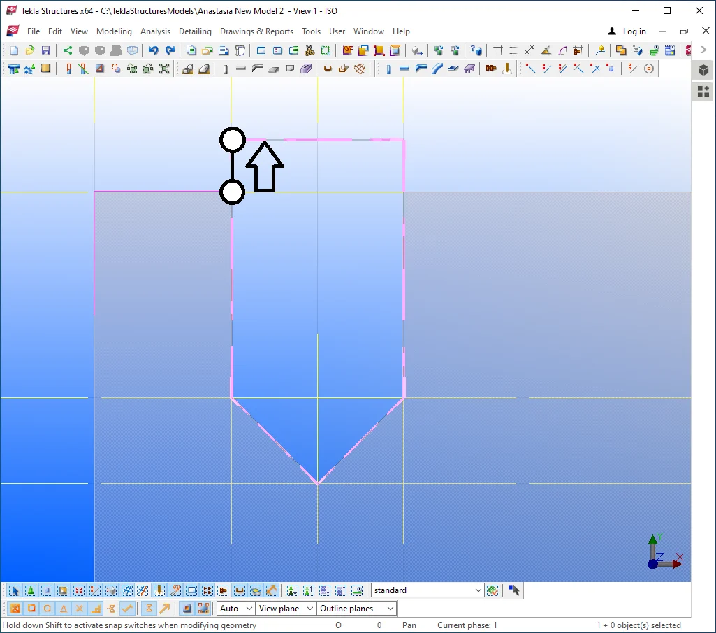
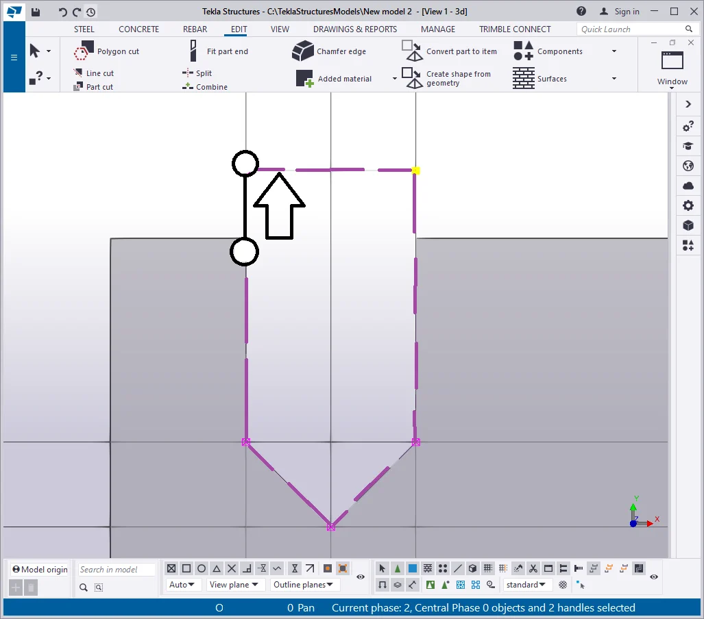
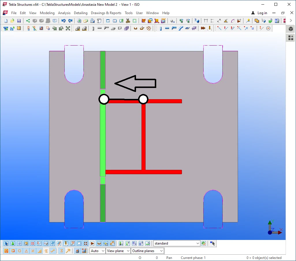
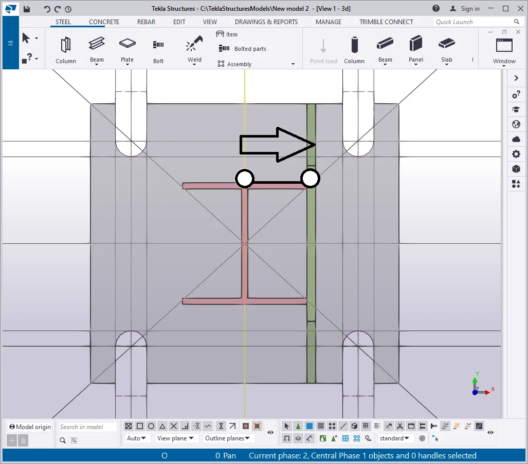
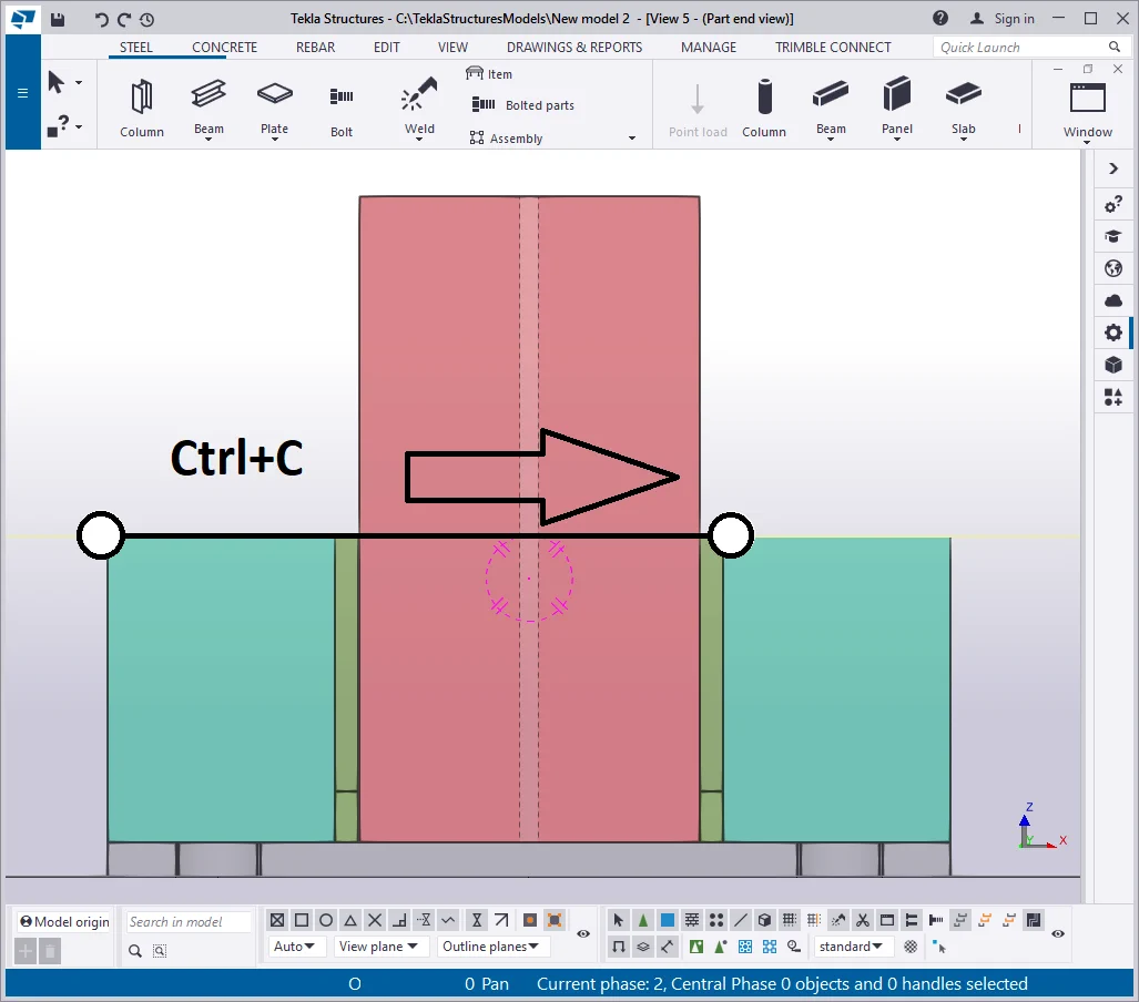
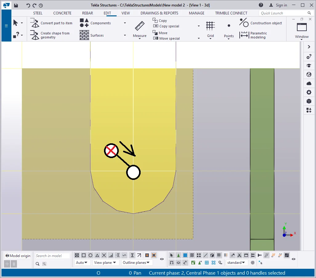
Select the upper points of the added material shape and move them up at 20 mm by using the Ctrl+M hotkey combination. This is to avoid allocating the cut line at the edge of the part.
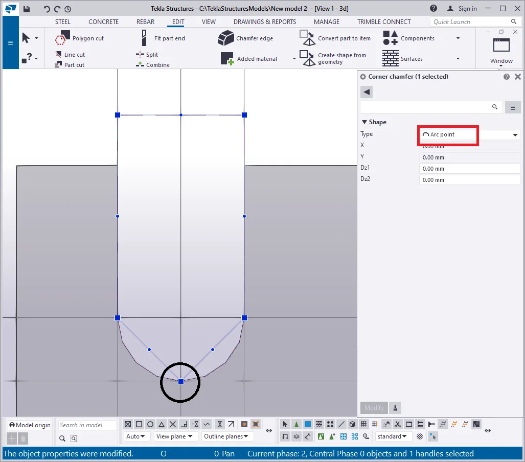
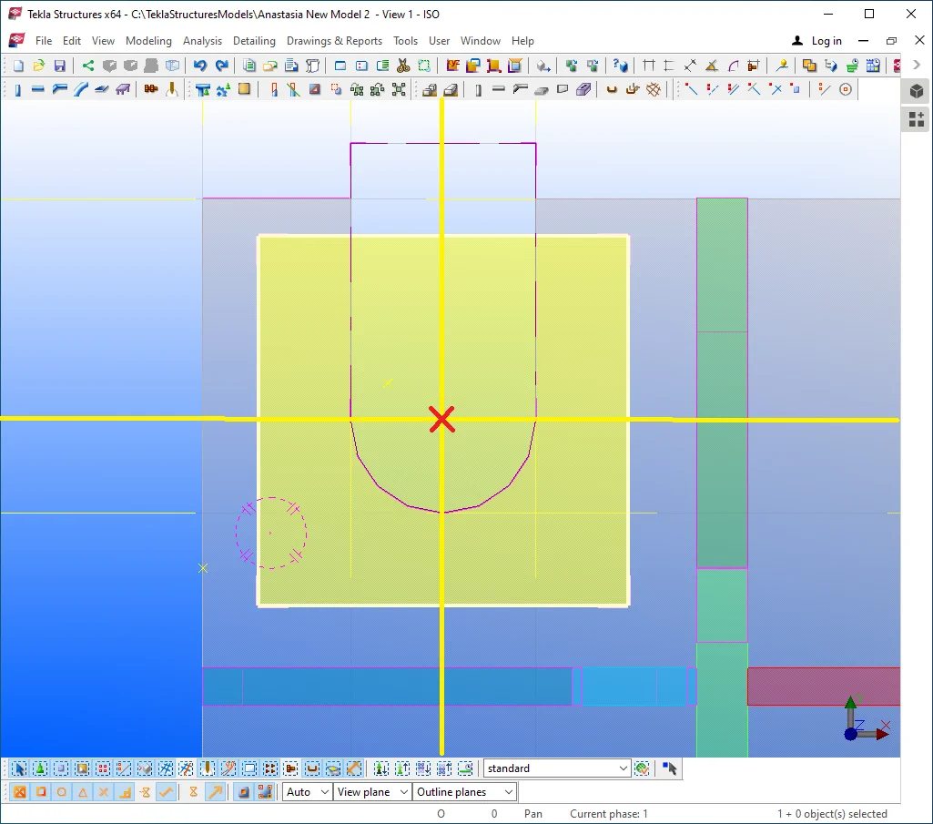
Referring to the below picture, select the bottom cut point, and by double-click on it, go to the “Chamfer properties“ menu and set up the chamfer type as “Arc point”.

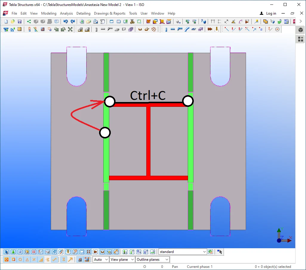
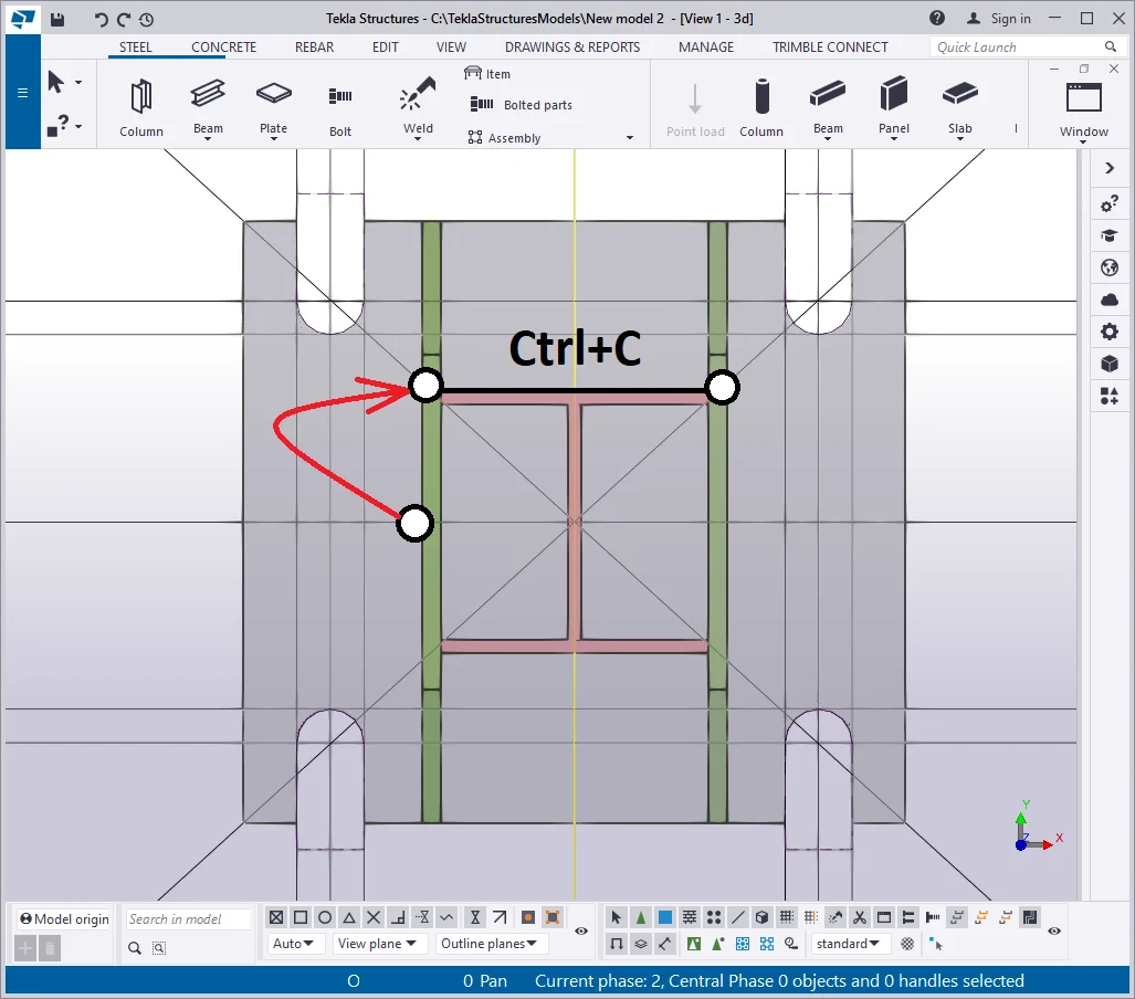
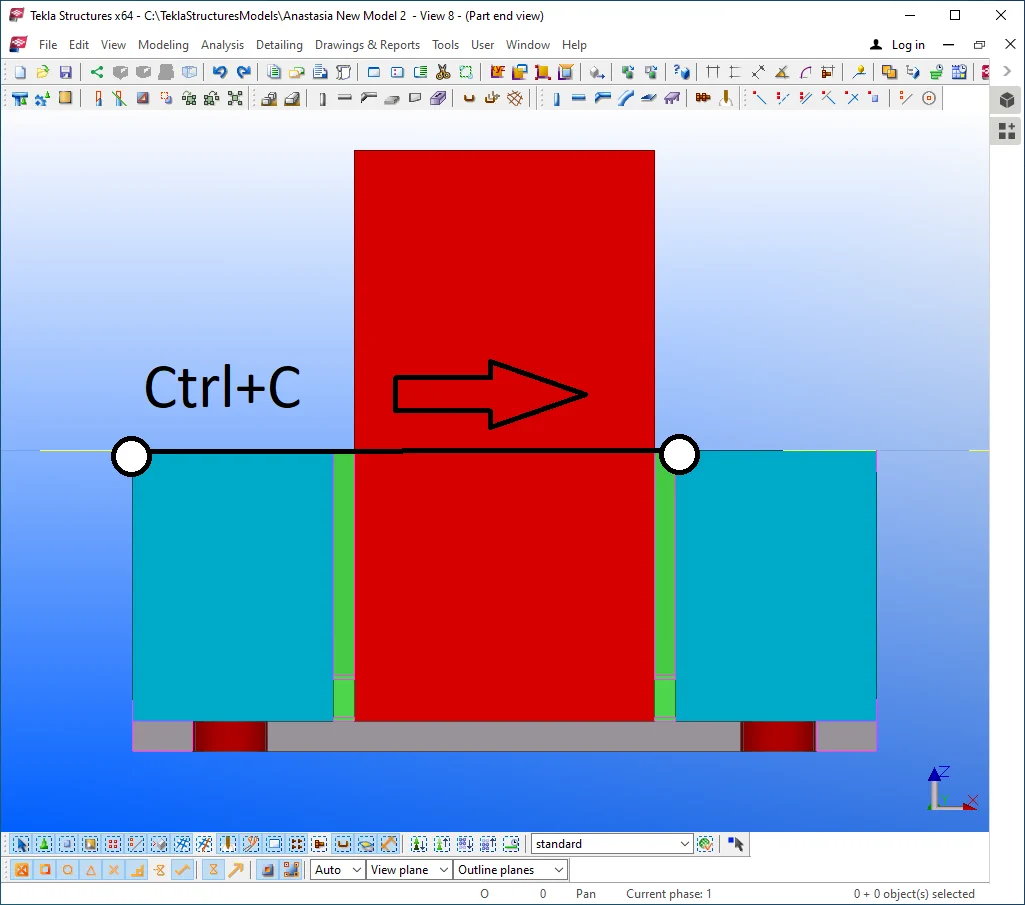
Copy the added material plate and paste it to the right at the required
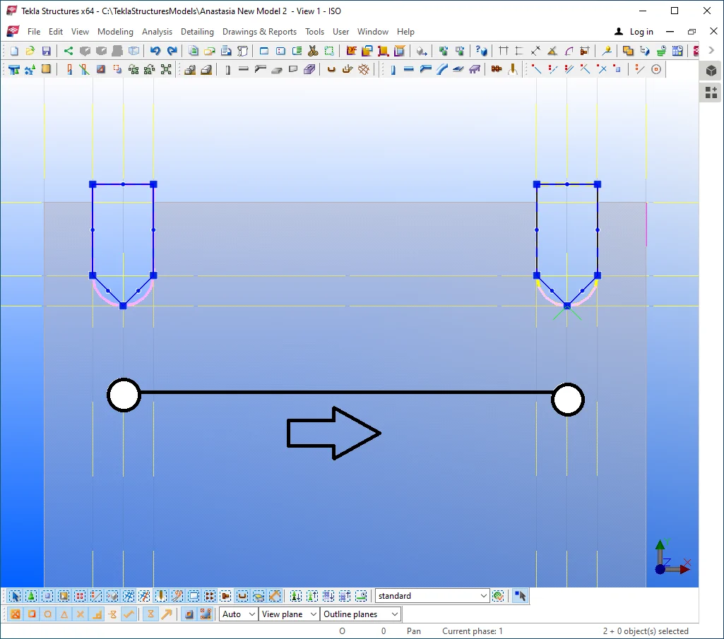
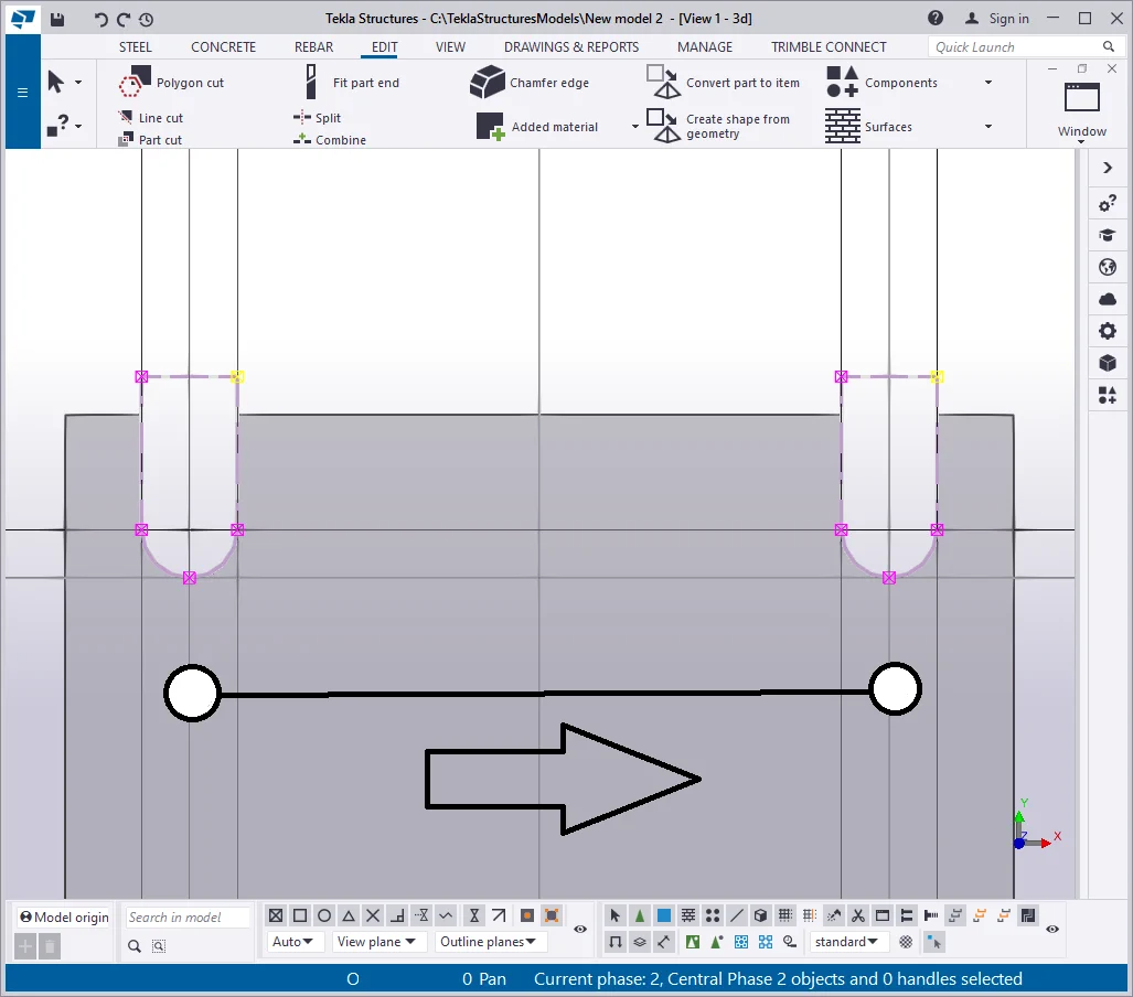
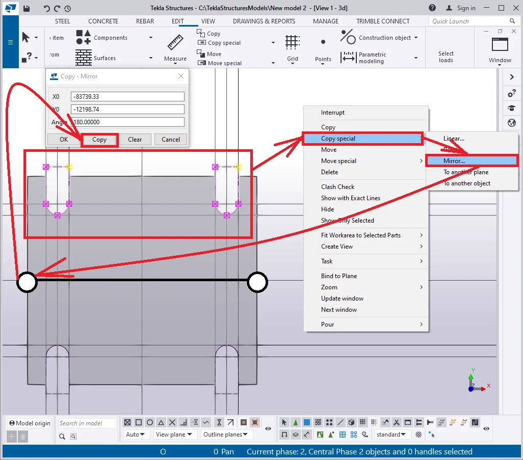
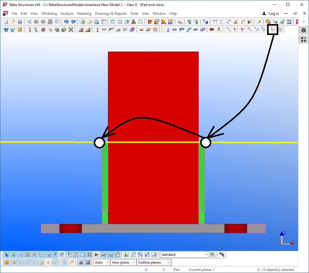
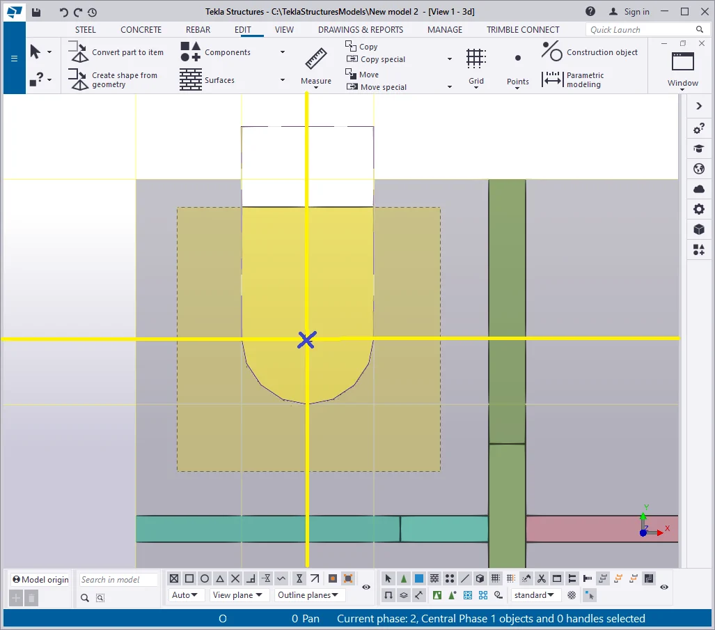
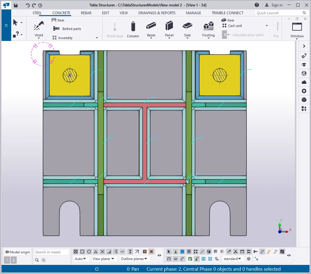
Select both added material plates and execute "Copy Special/ Mirror" to the bottom side of the initial plate. Before copying, make sure that the Z-axis is perpendicular to the eye gaze direction, if not, then go to the view plane.

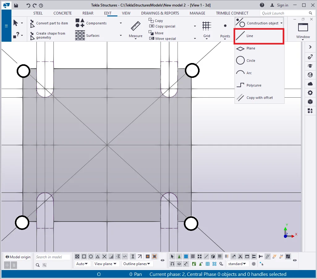
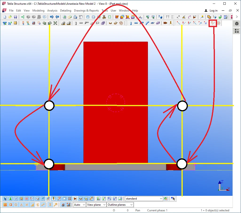
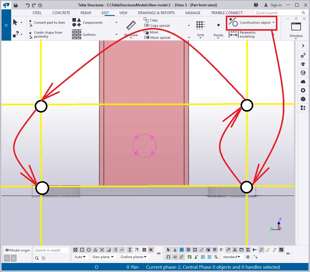
By using the construction geometry tools, create two more additional construction
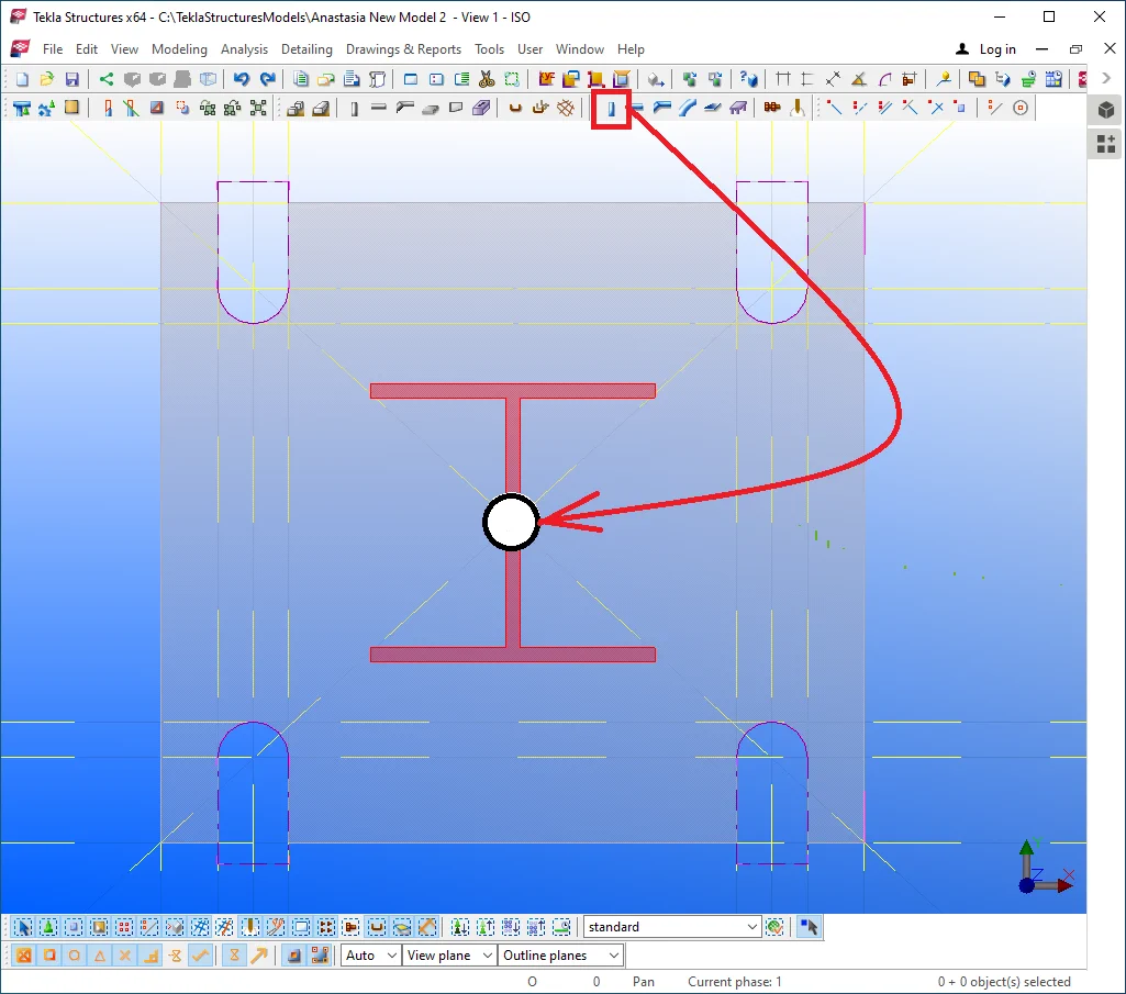
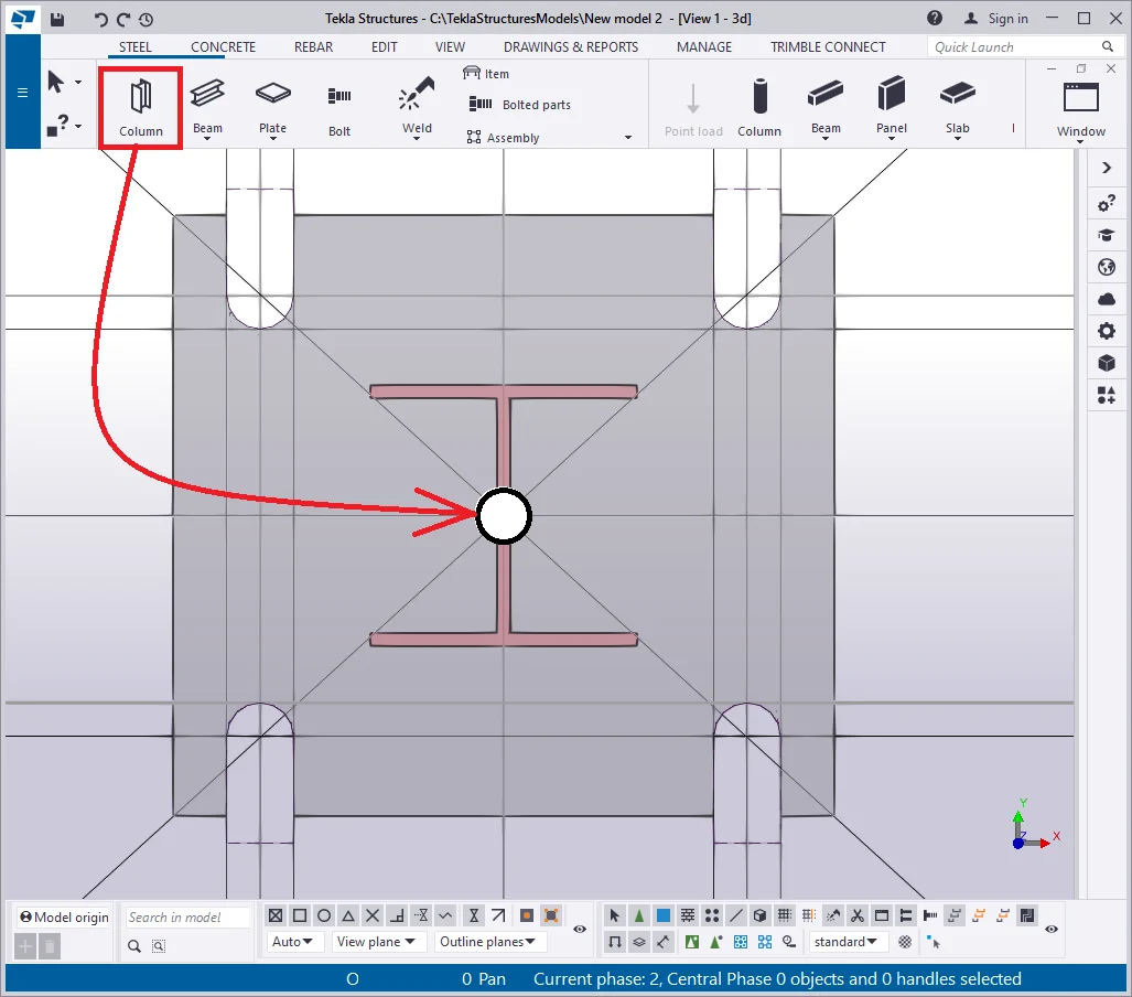
Create a column at the intersection point of the construction lines.
Configure the column properties according to the data presented below:
|
Profile |
Assembly prefix |
Assembly name |
Top position |
Bottom position |
|
HI196-10-10*200 |
C |
Column |
400 |
20 |
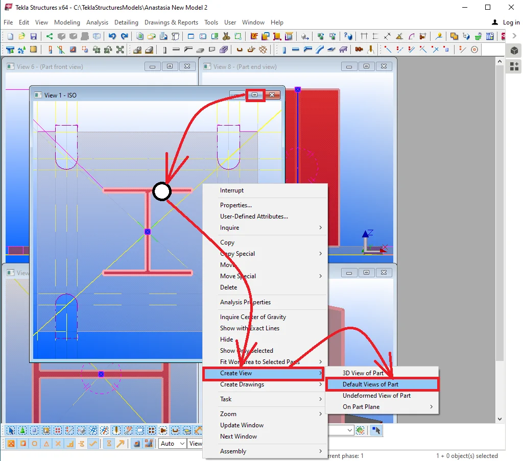
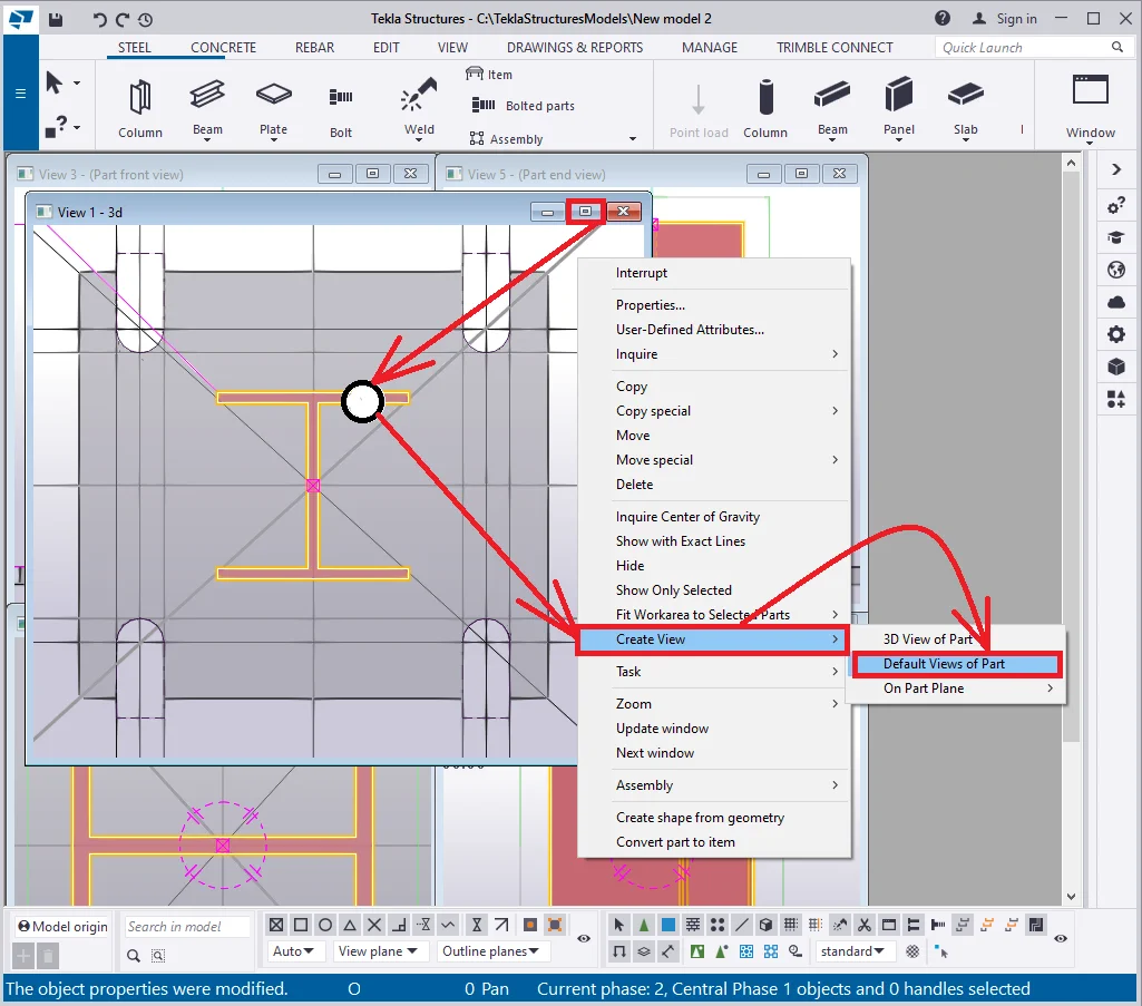
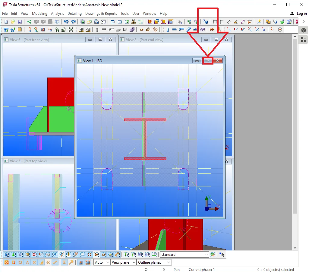
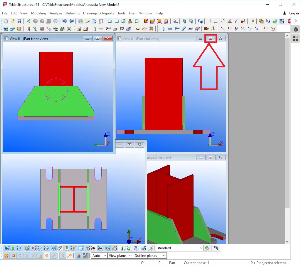
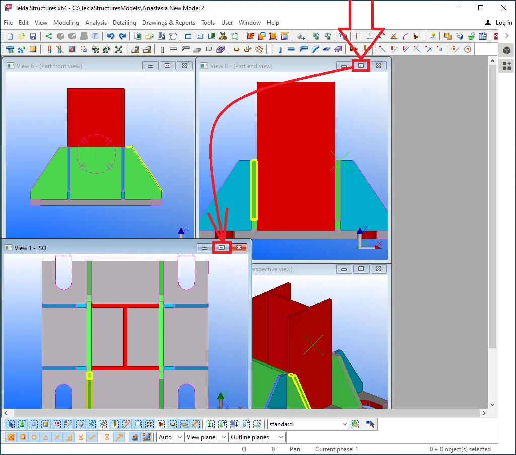
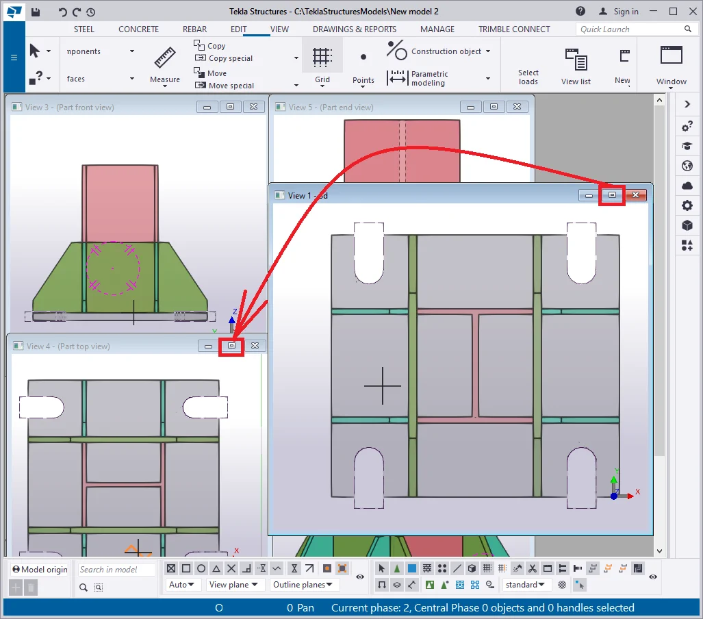
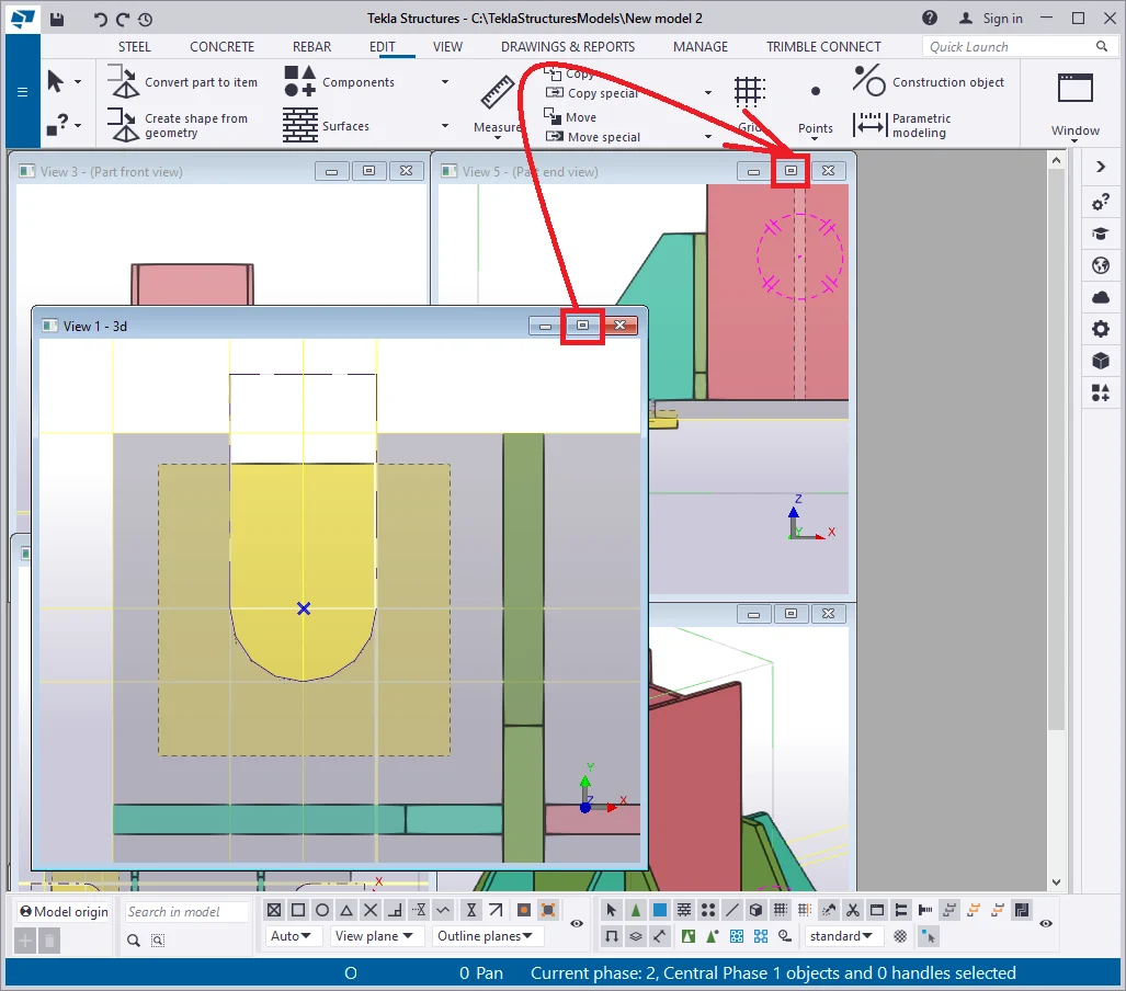
Minimize the view and create the default views of the column, by selecting
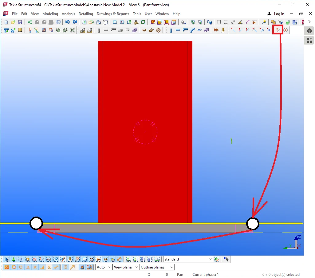
Go to the "Side view" of the column as it is shown below. Create
Copy/Paste the construction line at 180 mm in the upward direction.
Add up vertical construction lines.
Create a plate to be defined by the intersection points as is shown in
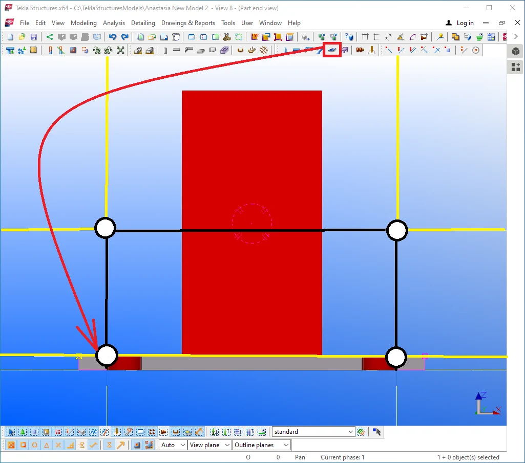
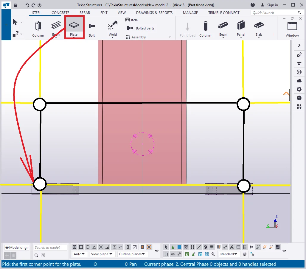
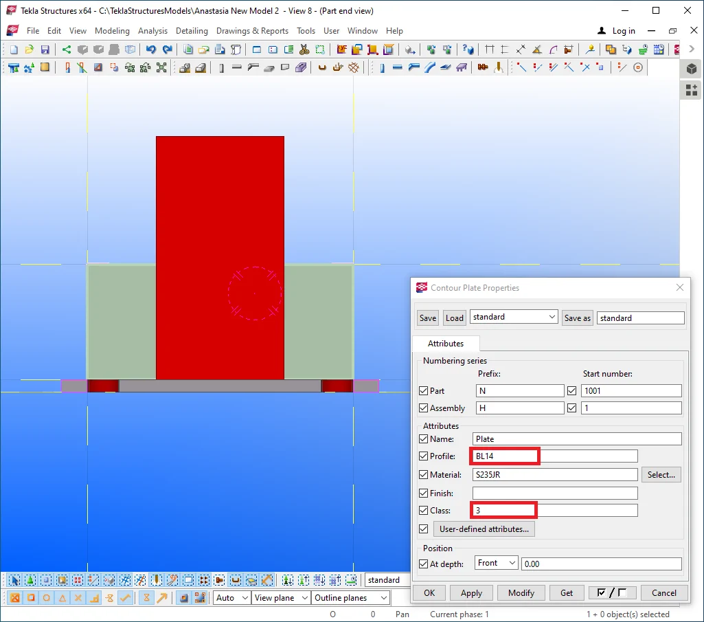
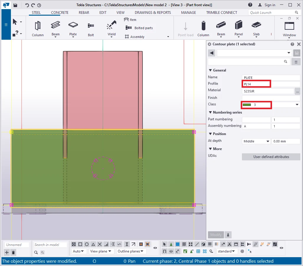
Set out the plate's thickness value at 14 mm and its class at 3.
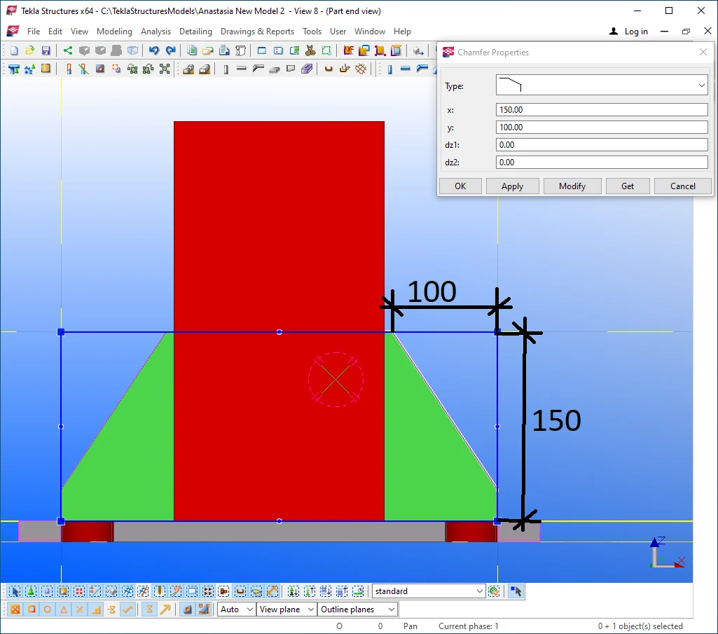
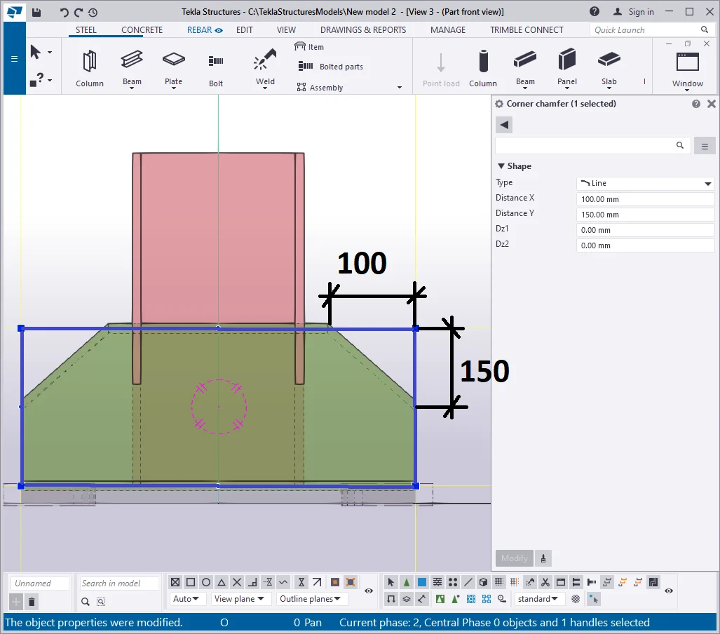
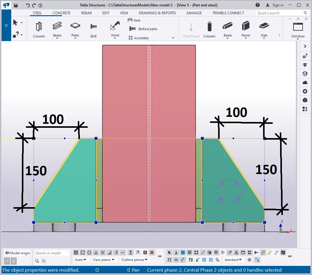
Select the new plate’s top points and configure chamfers to the "Line" type, with the X and Y values equal to 150 mm vertically, and 100 mm horizontally.
Note that depending on the side of the chamfer, the X and Y expressed
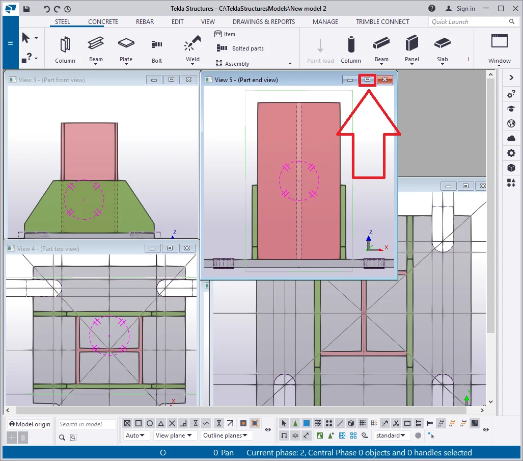
Minimize the "Side view" and go to the "Top view"
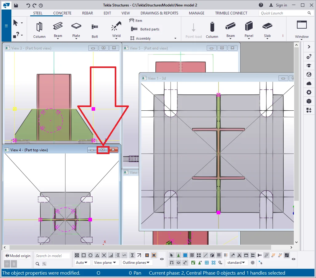
Configure the horizontal position of the plate to the left, and by using the Ctrl+M hotkey combination, move it in the way to get allocated at the column profile edge, as it is shown below:
Copy the plate to the right side of the I-beam to be allocated at the
The final output should be as follows:
Minimize the current view and go to the “Side view” of the
Create a construction line along the top surface of the plates.

Create a new plate of 10 mm thickness and the class value of 5 .
Copy the plate to the right side of the column.
Proceed to set out the chamfers as shown below:

Copy plates to get as shown below:

Switch to the “Top view”:
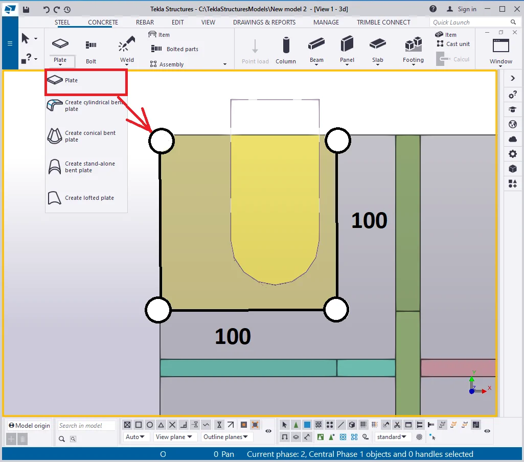
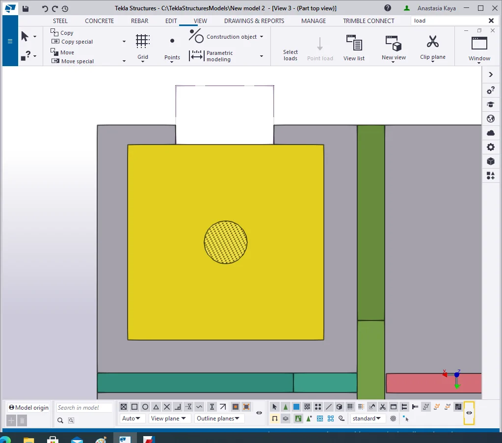
Let’s add up one more plate with dimensions of 100x100, a thickness

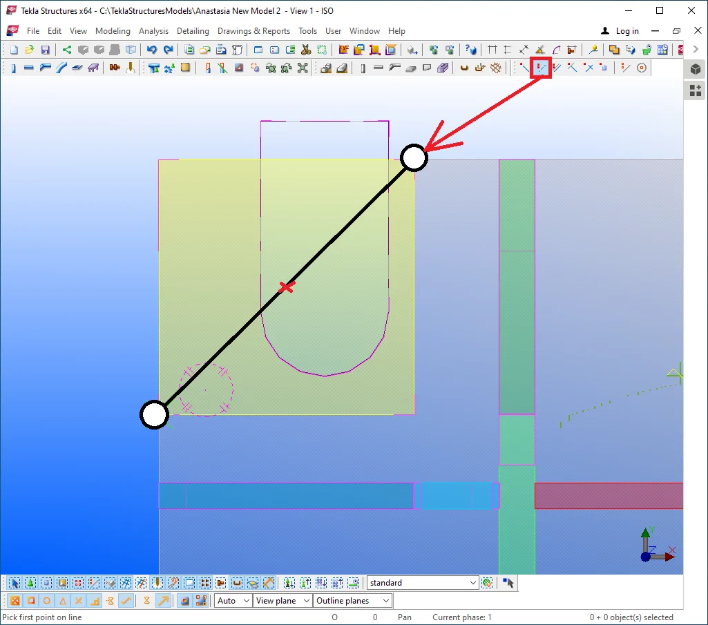
By using the construction geometry tools, add a center point at the new plate. In the main menu bar at the "Construction geometry" tab find the option: “On line”.
Make sure that in the properties menu the number of points is set out at 1. Thus between two points, a new point will appear right in the middle of the defined segment.

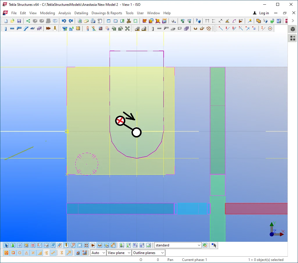
Press the "Esc" key to deactivate the “Create point on line” tool. Further, select the point created, and by holding on the "Shift" key pressed, select the plate as well. Enable the Ctrl+M hotkey combination and move the objects to the intersection point of the construction lines.
The final output should be as presented below:
Go to the “Side view” window.

Select the plate and move it to the initial plate’s top surface.
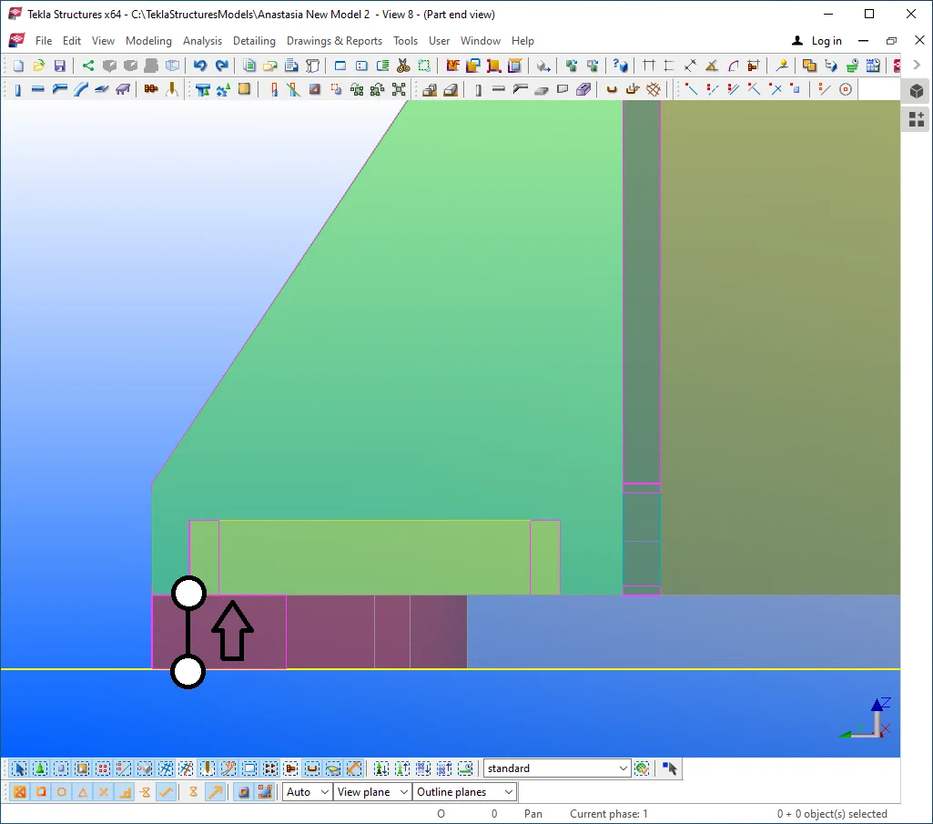
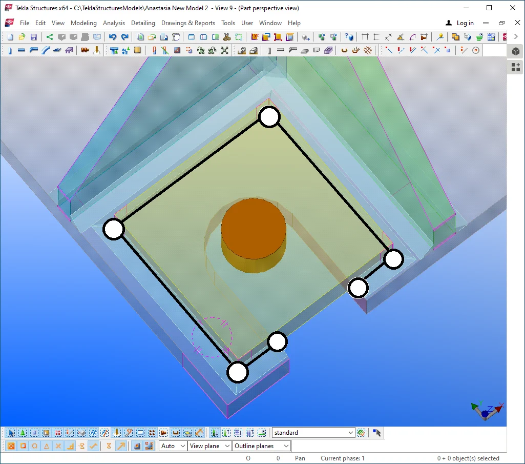
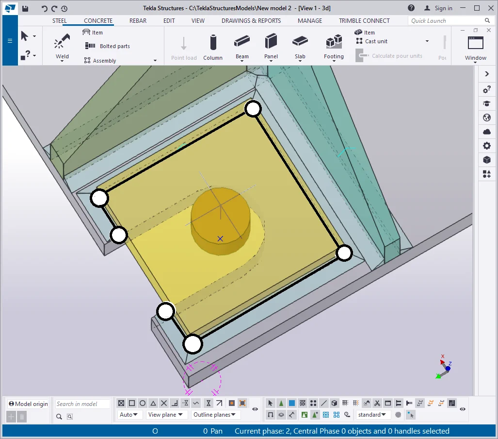
Let’s create bolt holes in the upper plate.
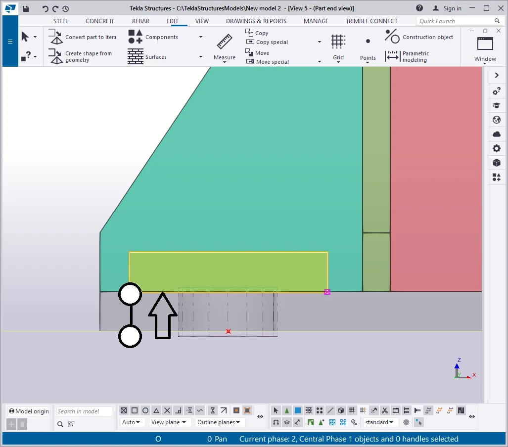
As you already know, bolted holes in the TS are created using the “Bolt”
Enable the "Bolt" tool and indicate the plate as a single joinable part, and set out the bolted joint direction by uniting the middle points of the sides of the yellow plate.


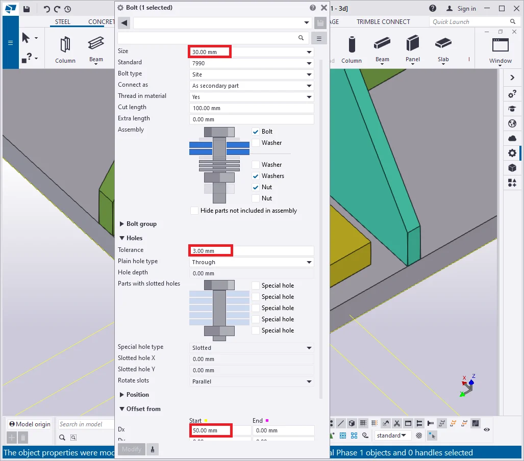
Let’s configure the bolted joint accordingly to the below table:
|
Size |
Bolt dist X |
Bolt dist Y |
Tolerance |
Dx |
|
30 |
0 |
0 |
3 |
50 |
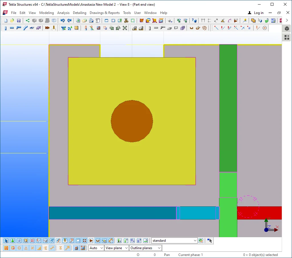
At the bolted joint properties window remove the checkmark for the bolt

The bolted hole is rendered as a non-transparent object.
Select the yellow plate and the bolted hole objects, and proceed to Copy/

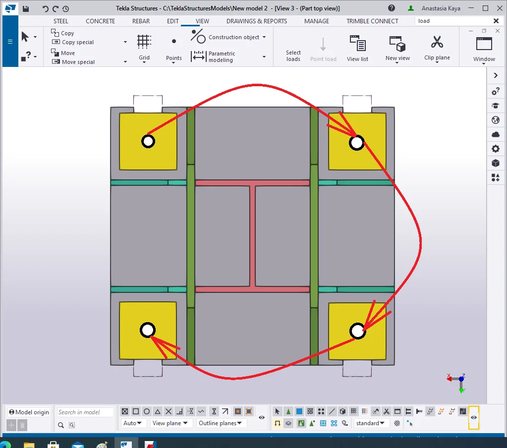
The final output should be as follows.

Now weld on the objects in the correct sequence.
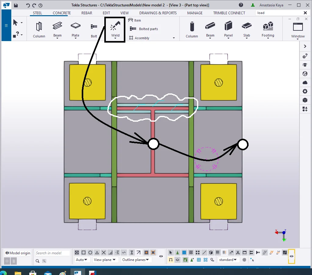
To facilitate creating welds, let’s set them out at the "Edge"
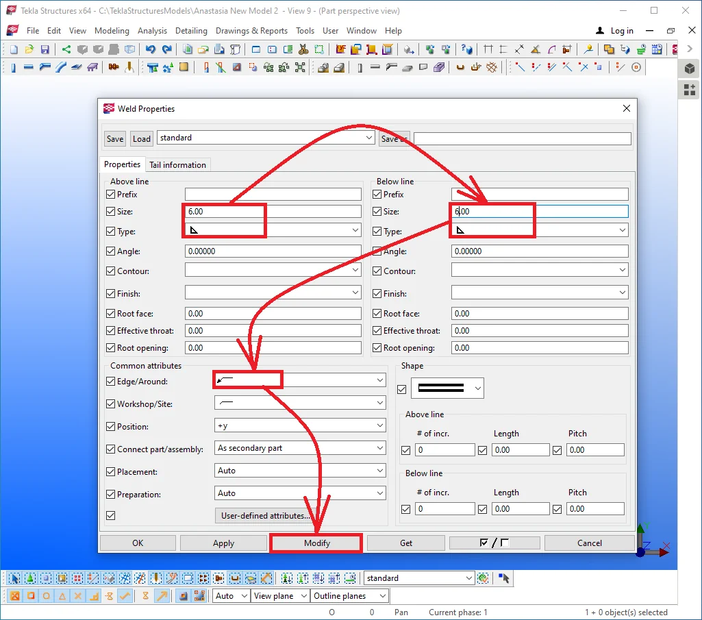
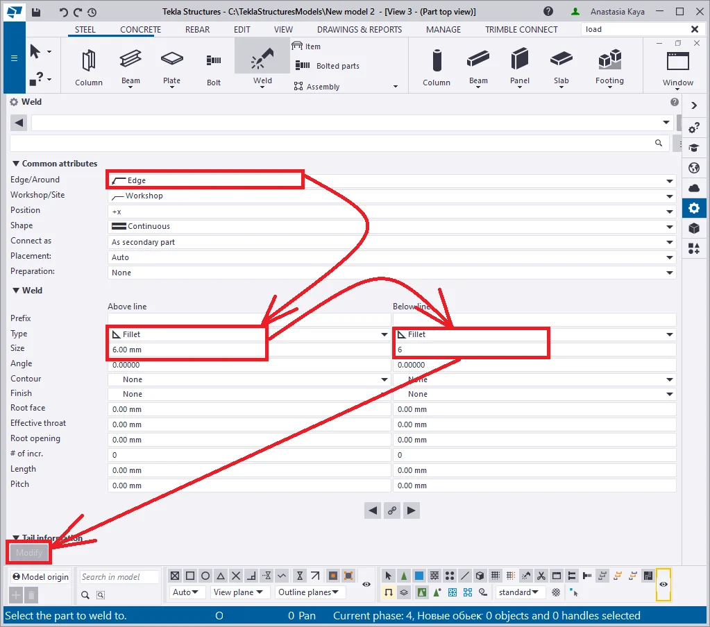
Create welds according to the below picture, and do not forget to toggle between the “Position “ field options to achieve the required result.
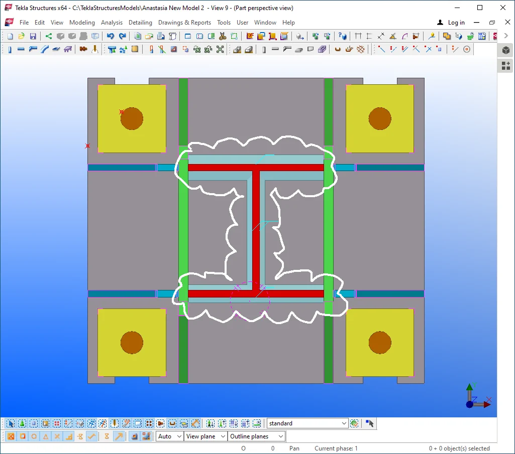
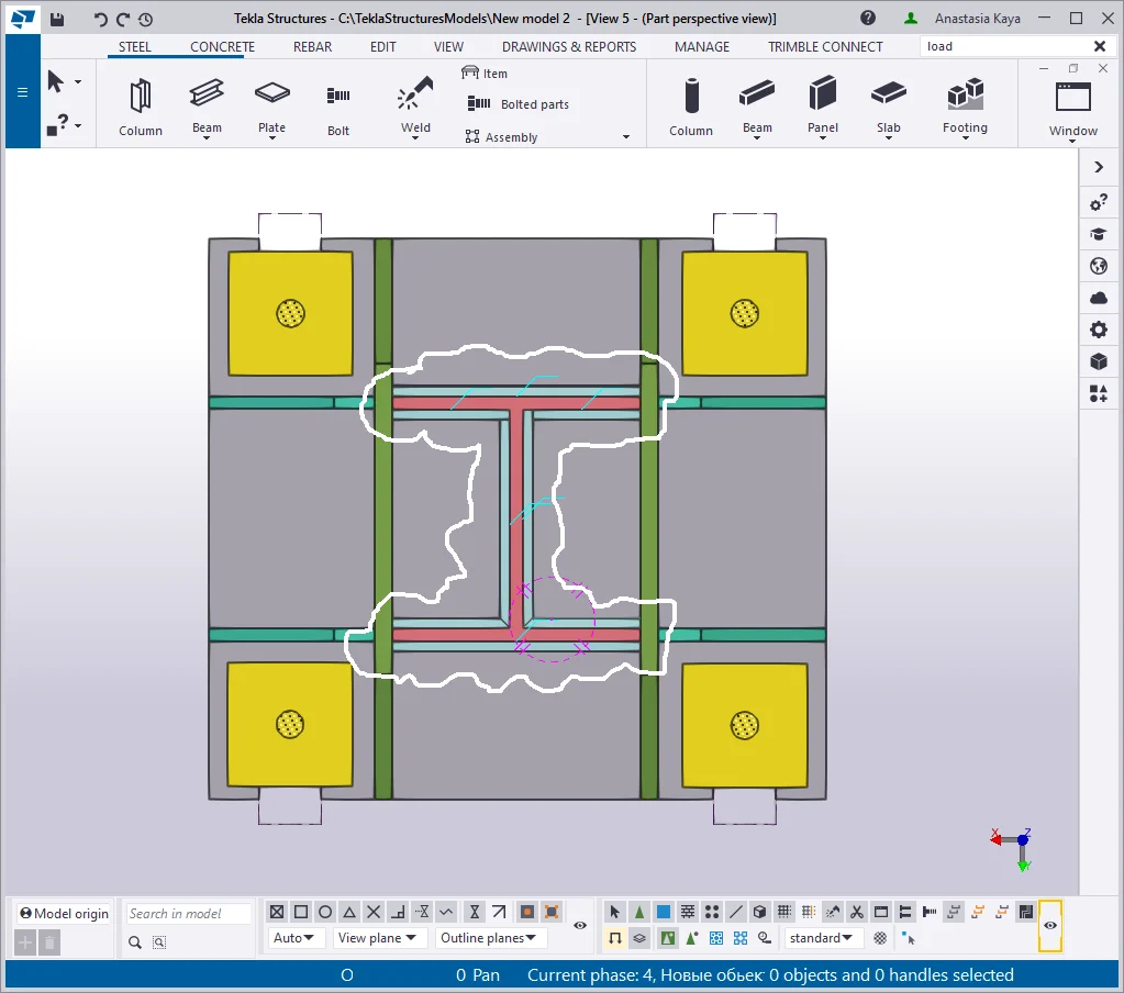
Continue welding up all the objects except for the yellow plates.
Let’s weld on objects not contacting the initial bottom plate.
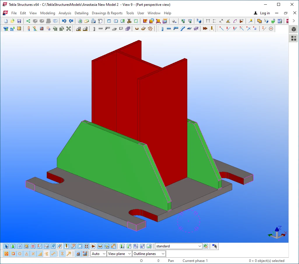
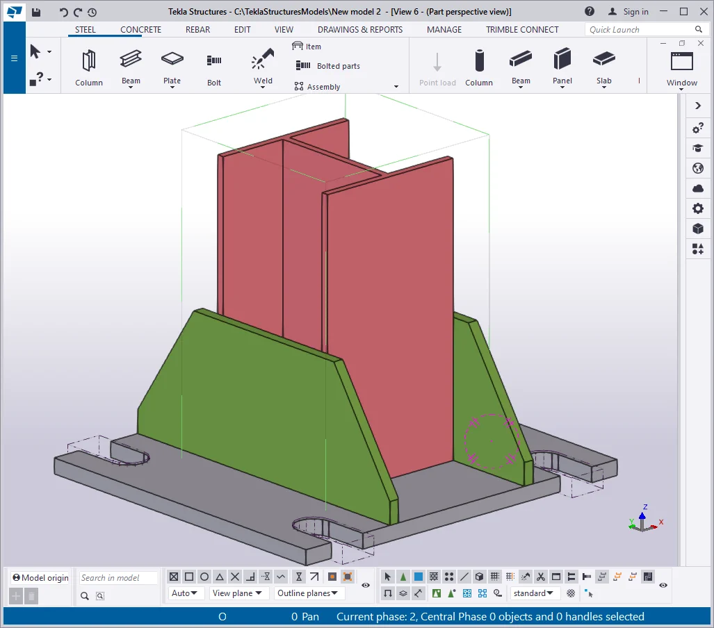
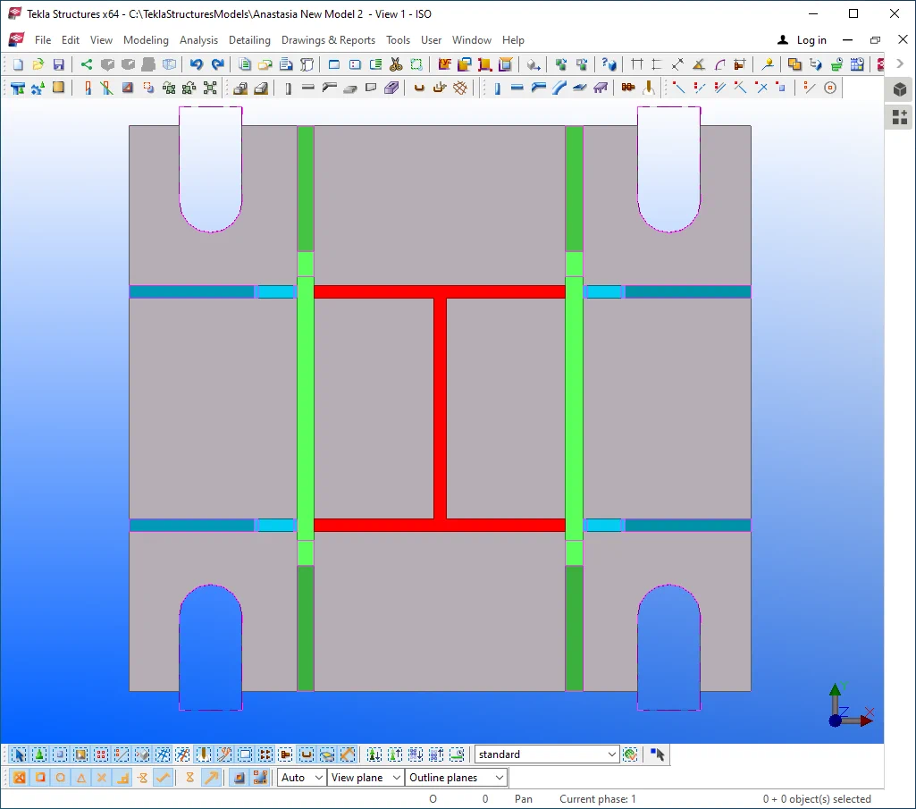
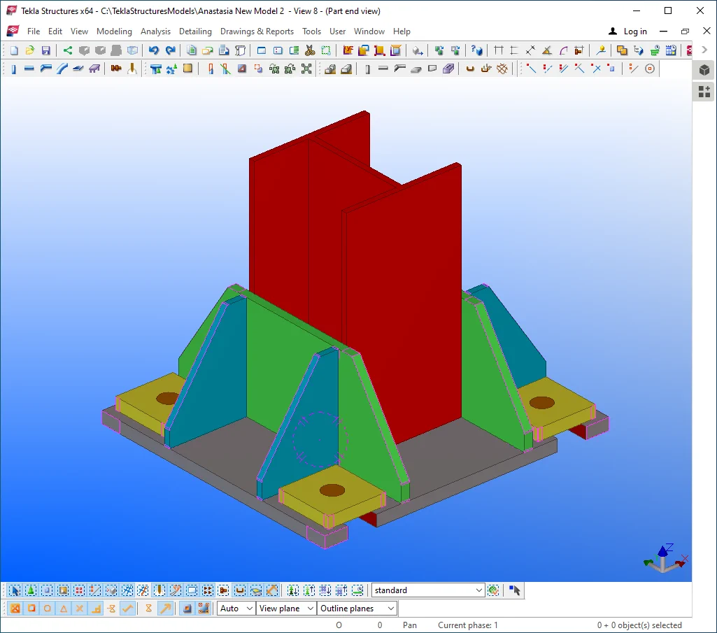
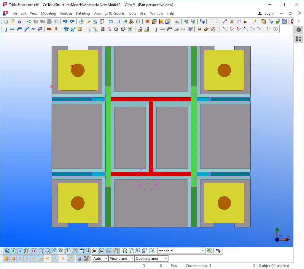
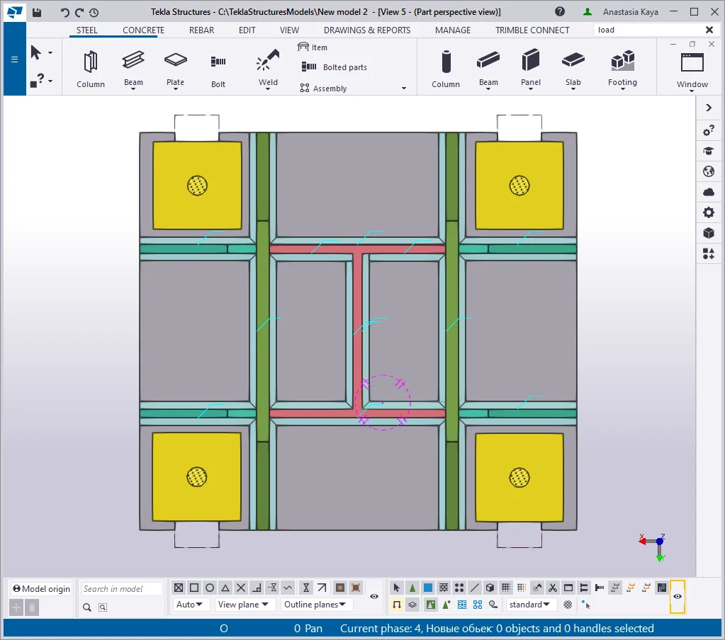
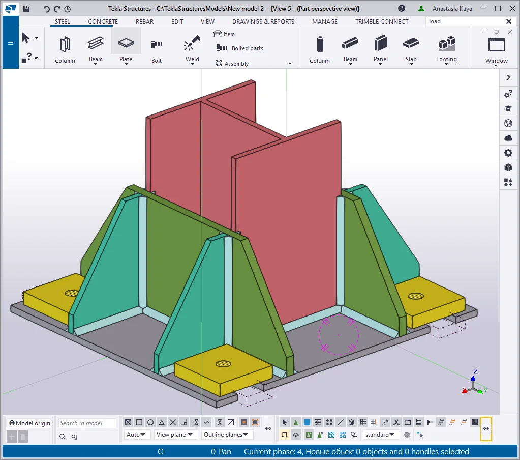
Compare your results to the below:

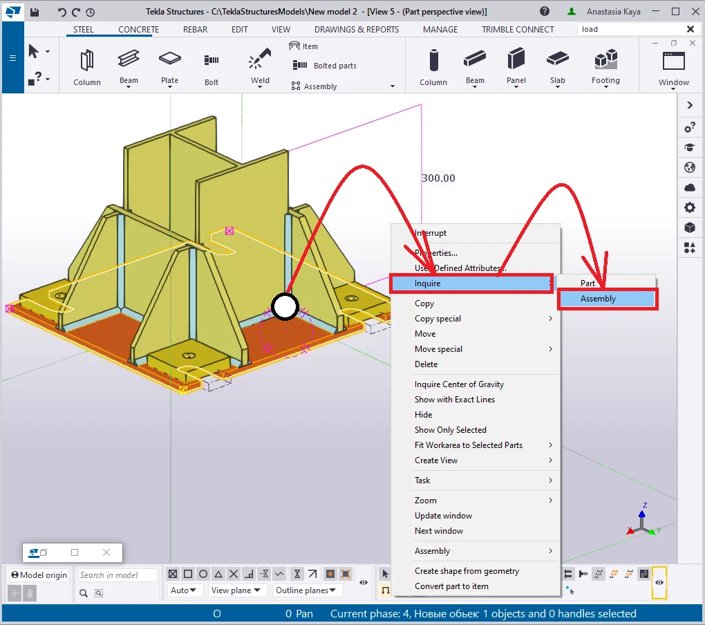
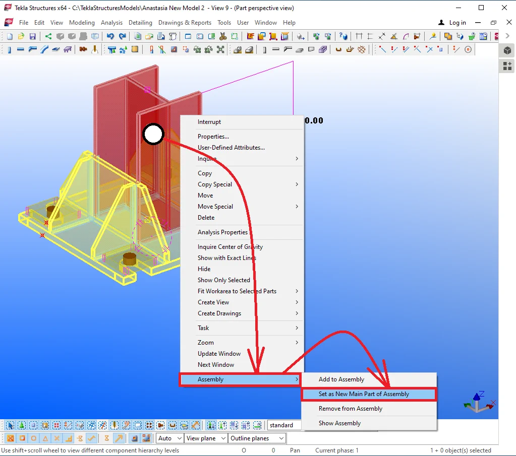
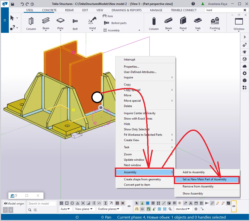
Inquire about the resulting assembly’s main component. For this purpose select any part, and in the right-click menu, enable the respective tab. The assembly’s main component is highlighted in orange color.
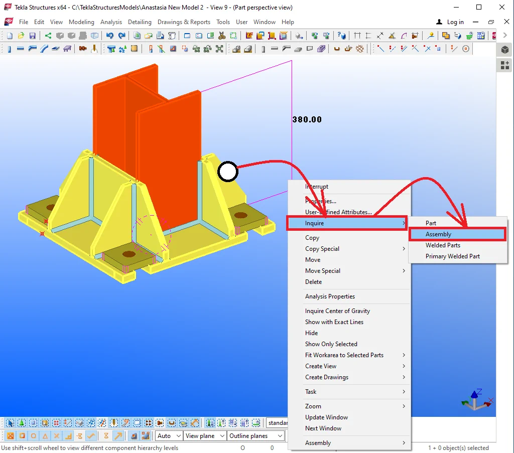
As we have previously discussed, the assembly’s main component shall be defined by the rolled profile body. In the current case study, it should be the I-beam body defining the assembly's name and prefix, and ignoring the respective of the other components included.
It is important to mention that every subsequently created weld reappoints the main component. To correctly set out the main component it is required to select the weld, which refers to the main assembly part, or upon welding on completion, forcefully indicate it.
In the current case, forcefully set out the main component.
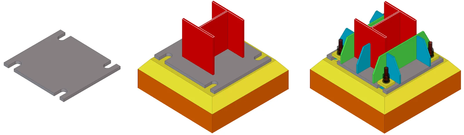
Now let’s clarify the yellow plate assignment. The current exercise represents a field case of a column base, where the column is put at the concrete and is supported by a plate. During the installation of the column, the plate bolts are already located into the concrete pour and are sticking out.
As the set-on accuracy of the bolts of the plate can be insufficient, with this purpose elongated bolted holes are created. The cuts drawn up in the initial plate allow shifting the column at the distance to 5 mm in all the possible directions to certainly install the column to the required position.
The upper washers (yellow plates) are necessary for preventing bolts from caving into the elongated holes and are to be welded on after definitively setting up the column.
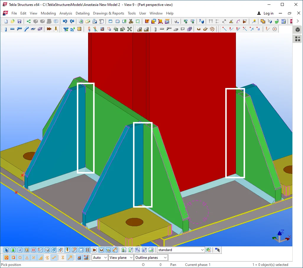
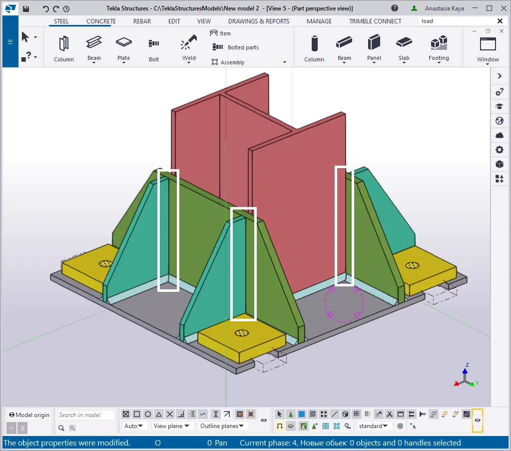
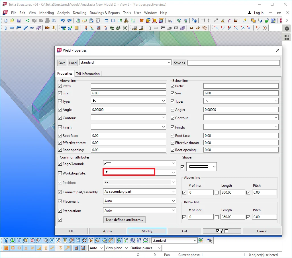
This column base type has been taken as an example for the reason that it requires creating elongated holes, which are generally seldom used, and are not possible to be established employing the “Bolt'' tool. All the other holes in the model shall be created by using the “Bolt” tool, otherwise, not respecting this rule is considered a critical error. Also, the yellow washers are to be welded on in-situ after the column installment, taking into account the abbe offset value. Create a polygon weld.
Switch the weld type to “Site”
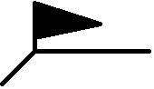 .
.
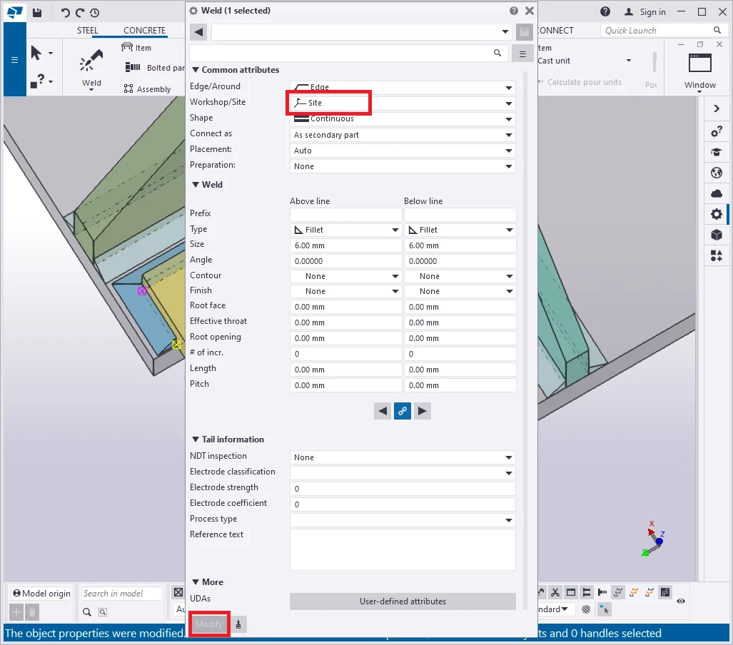
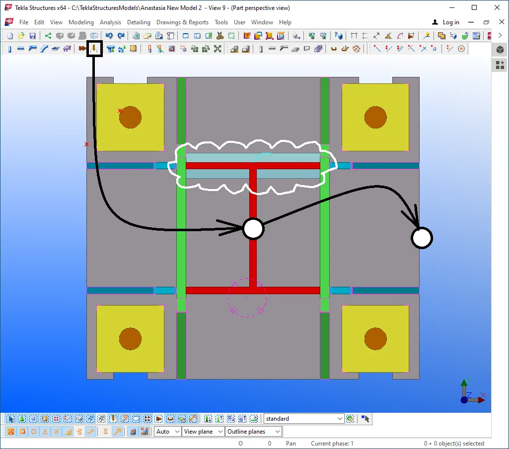
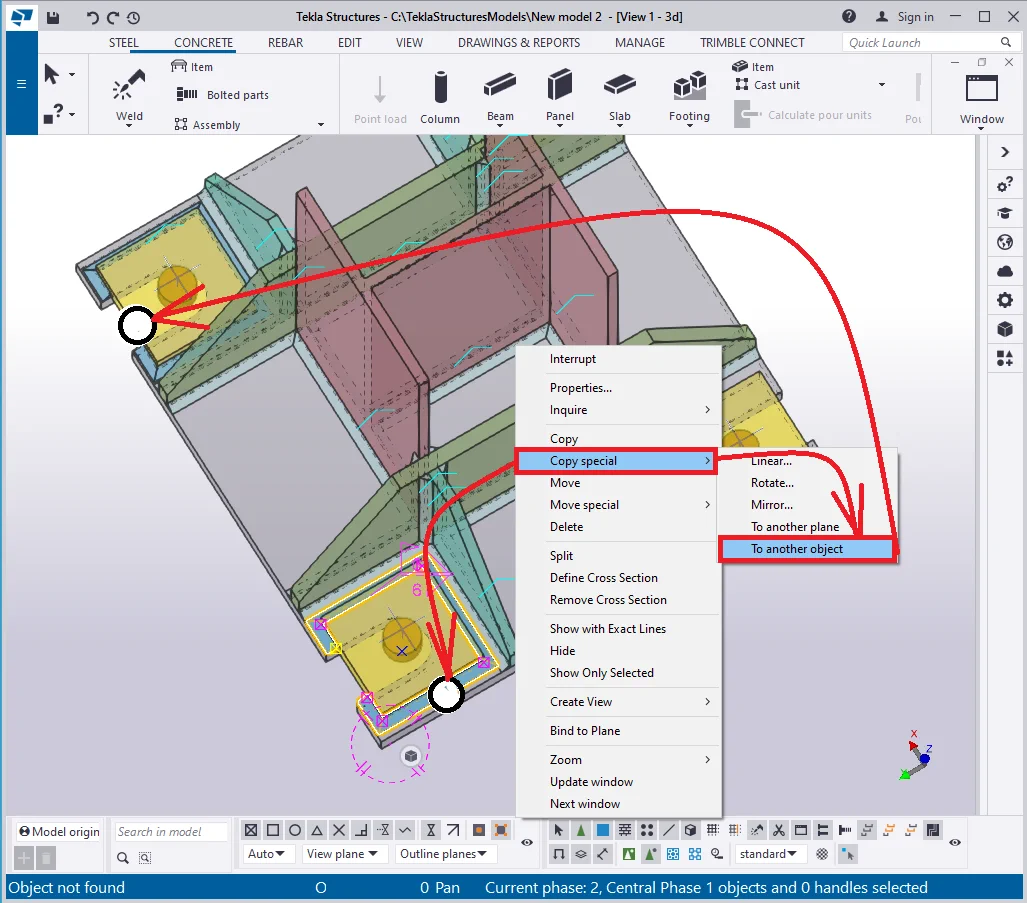
Execute "Copy special/ To another object" of the weld to another
yellow plate.
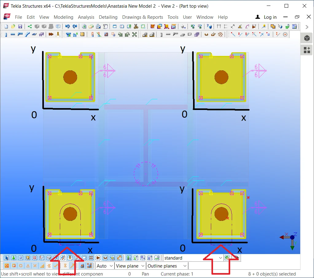
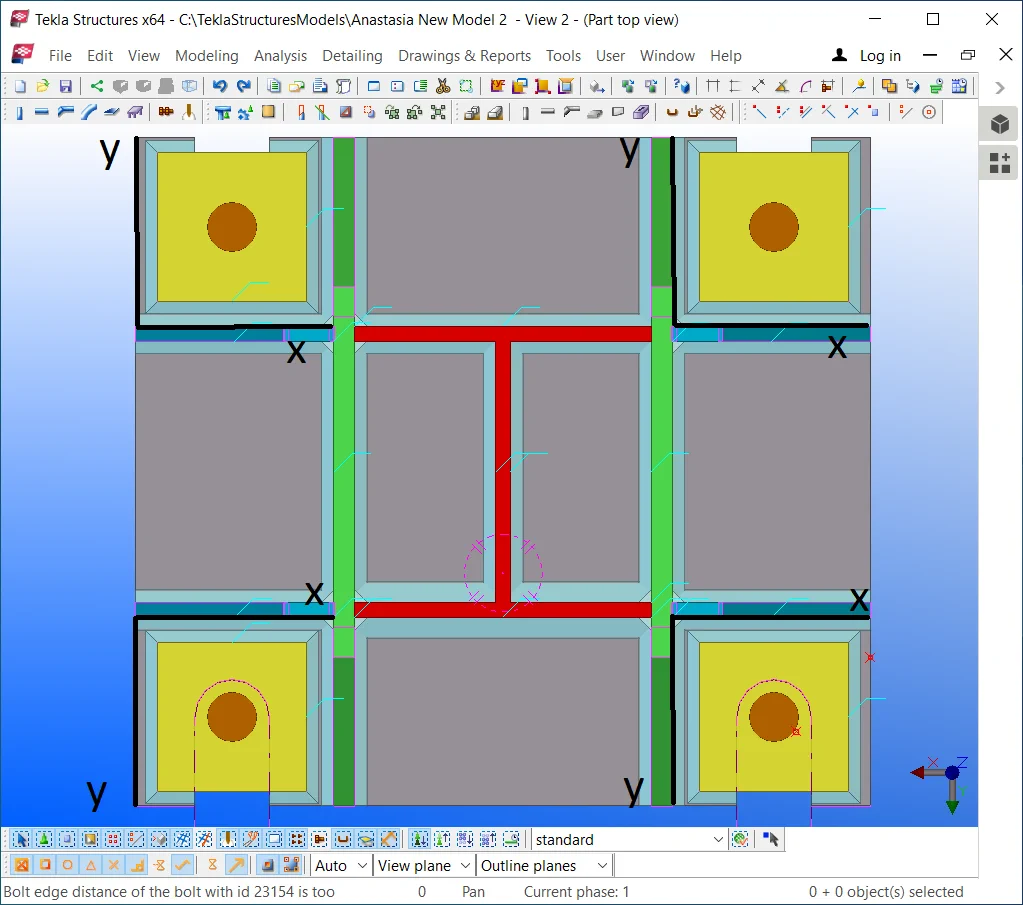
Note that two objects are welded on properly, but the other two are not. The reason is that the local coordinate systems of plates are completely identical, and copying the weld seams duplicates their orientation.
Thus for the upper yellow washers, it shall be applied to the mirrored
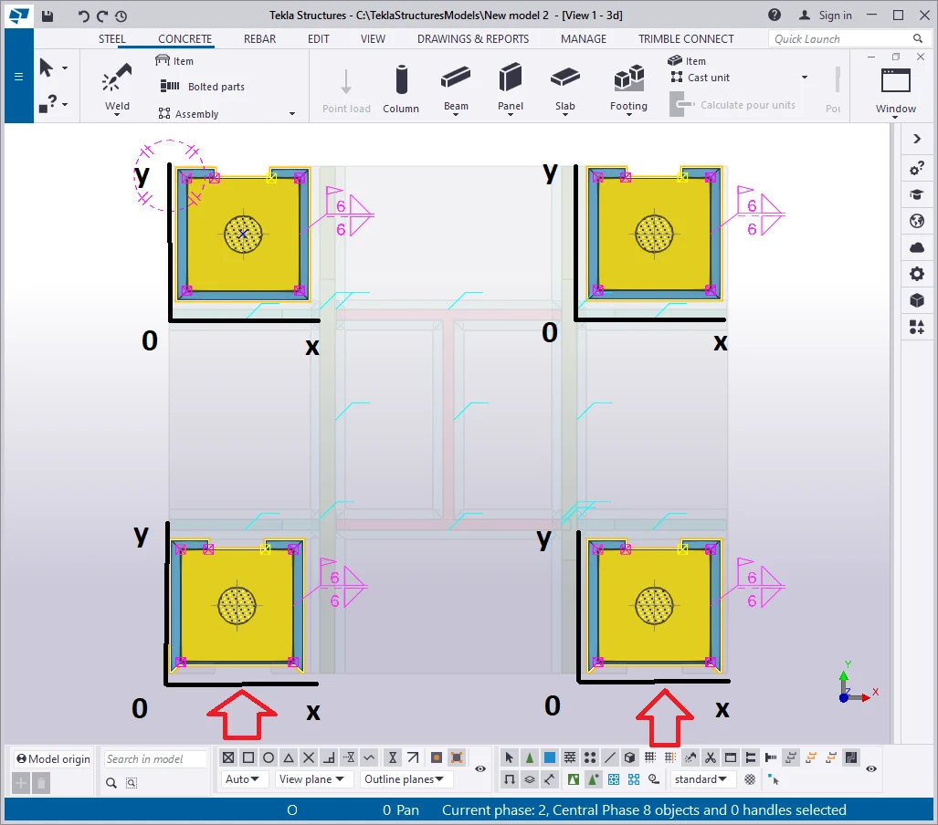
Delete the upper yellow plates.
Select the yellow plates by using the "Shift" key and by not
Further, execute "Copy Special/Mirror" of the selected

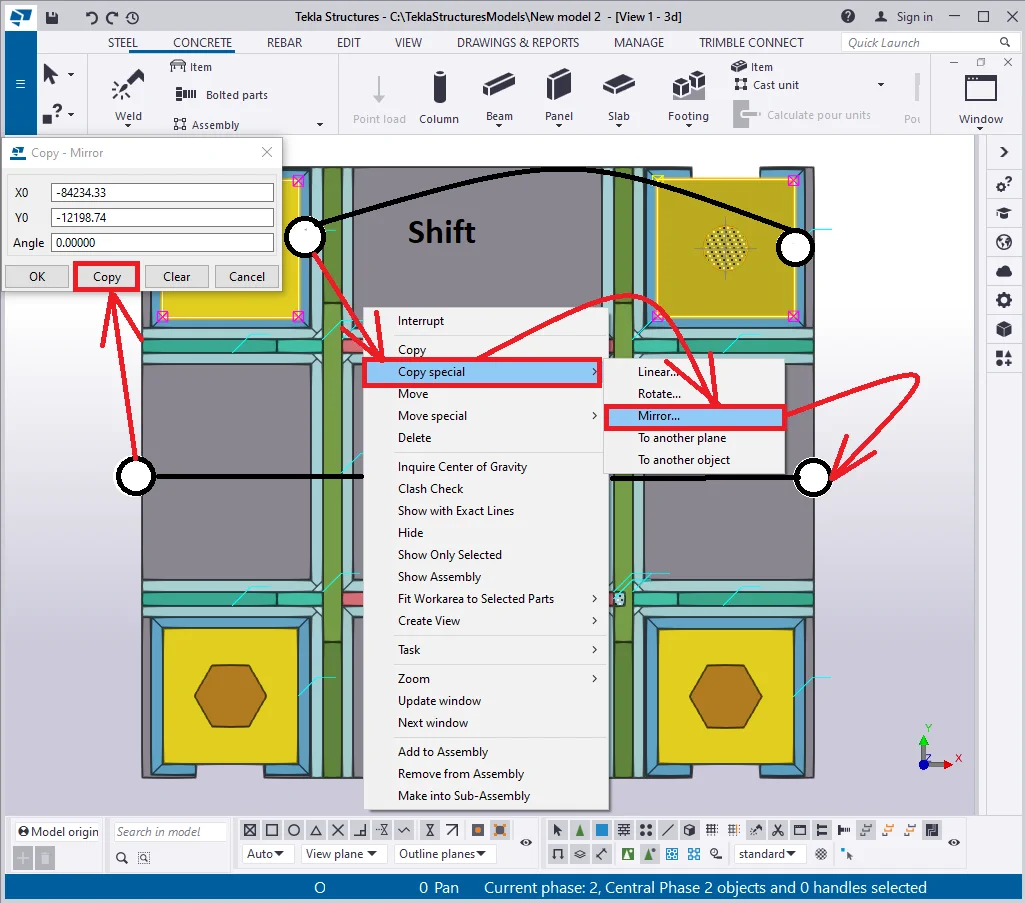
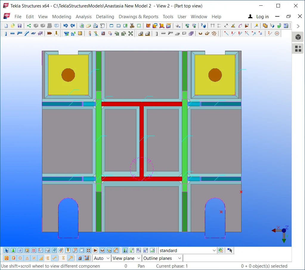
Note that the weld seams and bolted holes are copied along with the plates, despite the fact we have not selected them and their alignment is correct. Here we can deduct one more property of welding seams and bolt holes, which is: copying a welded-on object automatically initiates copying welds associated with it. It is of high convenience as the user does not need to select multiple associated objects and thus avoids committing errors by missing out on any of them.
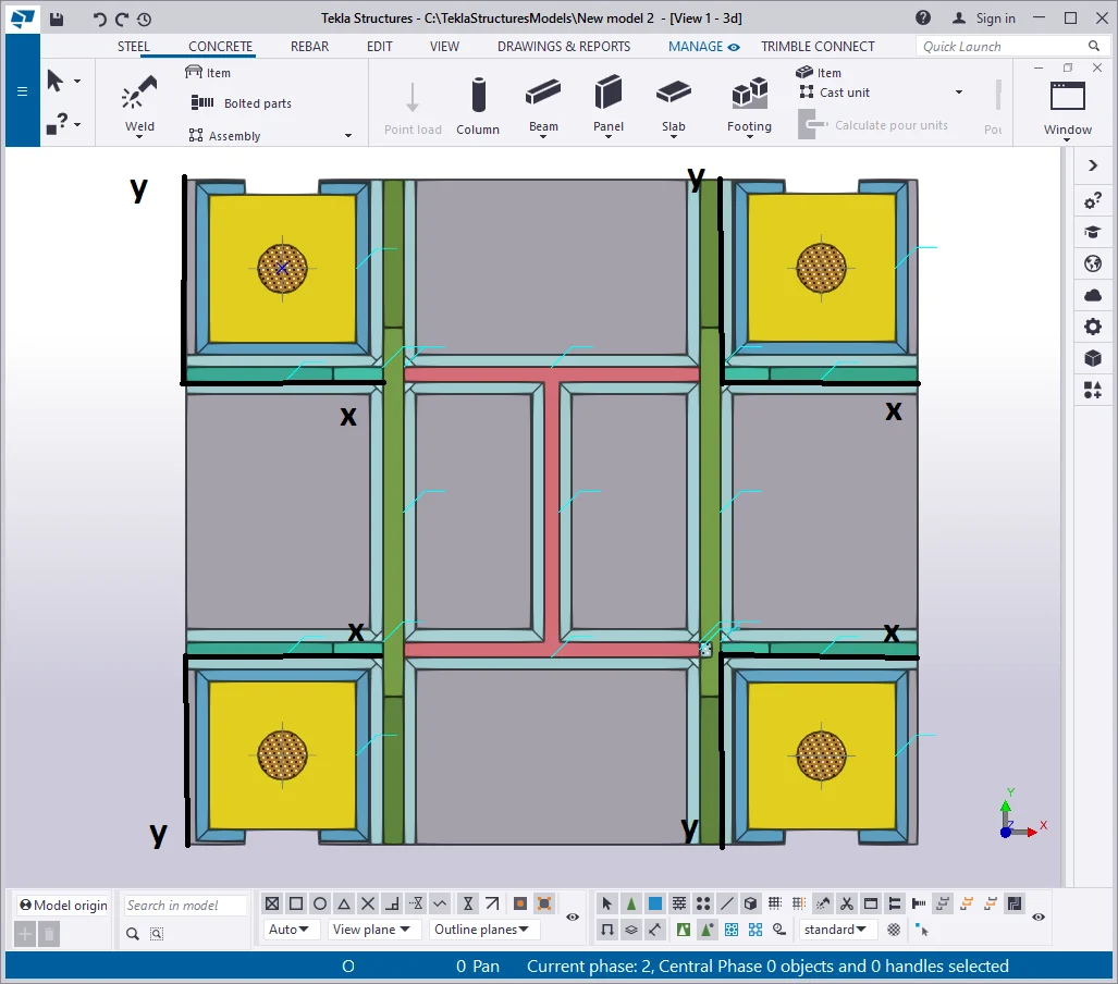
The final result is presented in the below picture: