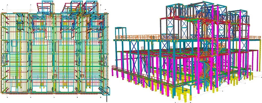
One of the basic ways for creating a non-uniform beam is to create a standard beam and respectively configure its profile. The non-uniform beams created by this method can be used for transmitting to the calculating software. Also, this method can be used if there is no need to separately take account of the materials used.
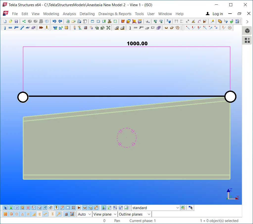
Create a simple beam of 1000 mm in length.
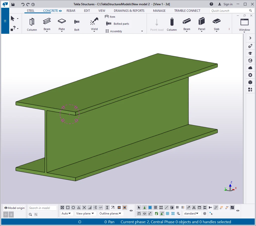
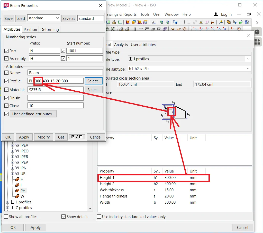
In the “Beam Properties” menu, go to the "Profile Catalogue" and write into the search box: “*PHI”.

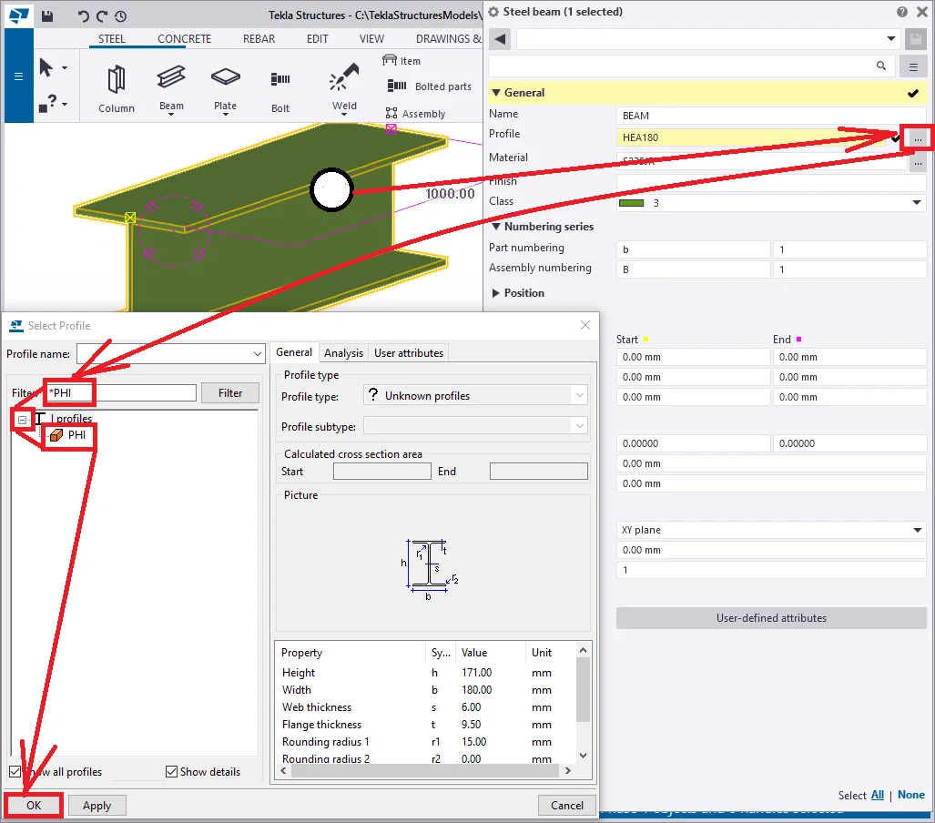
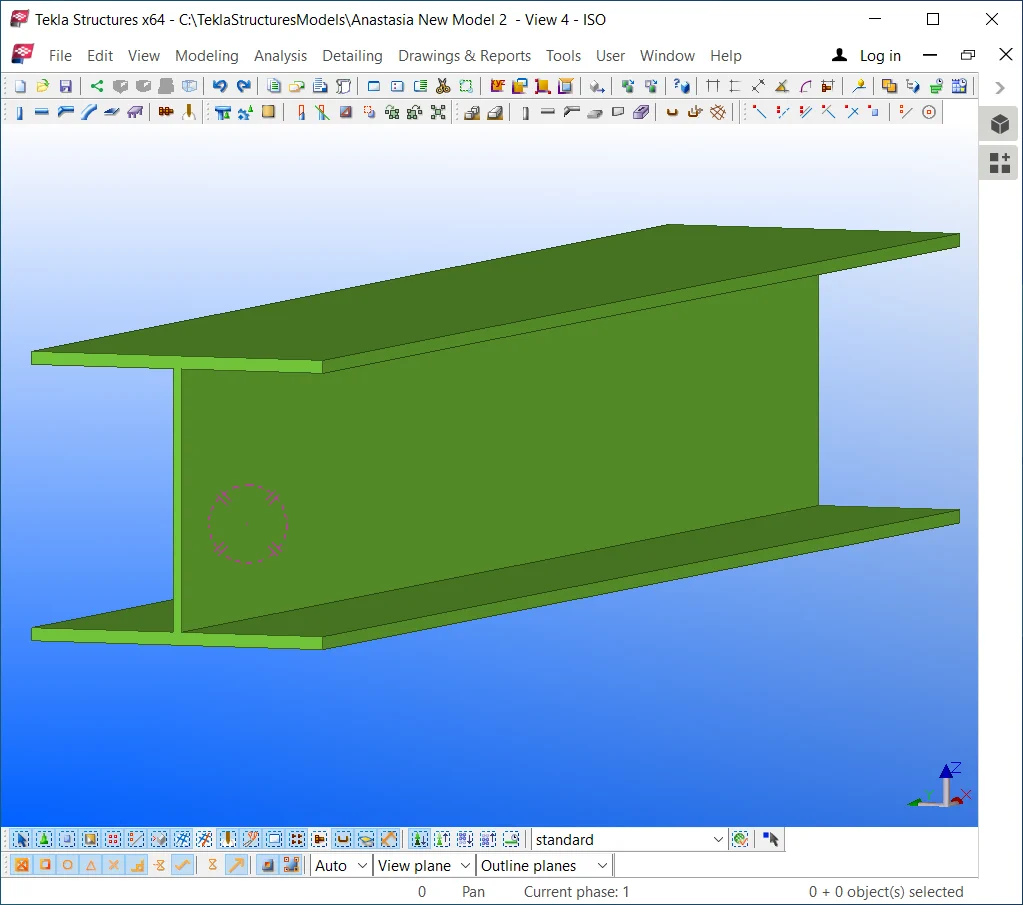
This profile type is defined by I-beam height variance at its starting and endpoints. It allows setting out the I-beam's height at its starting point and the I-beam's height at its endpoint. In the below picture you can see the table with editable profile parameters.
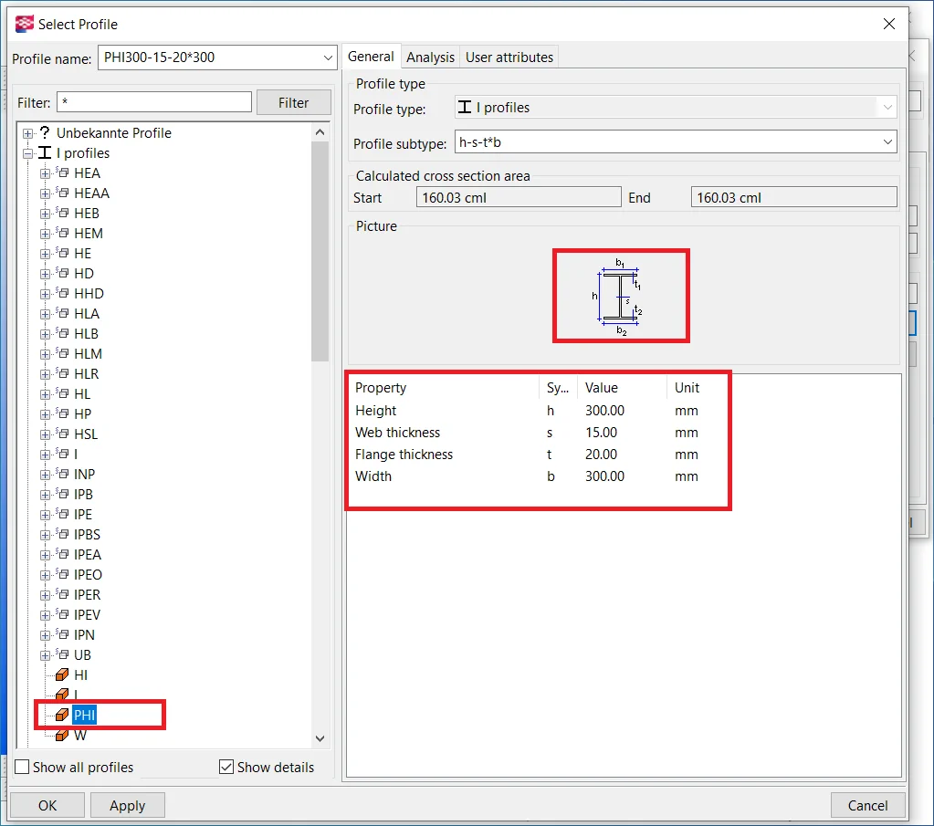

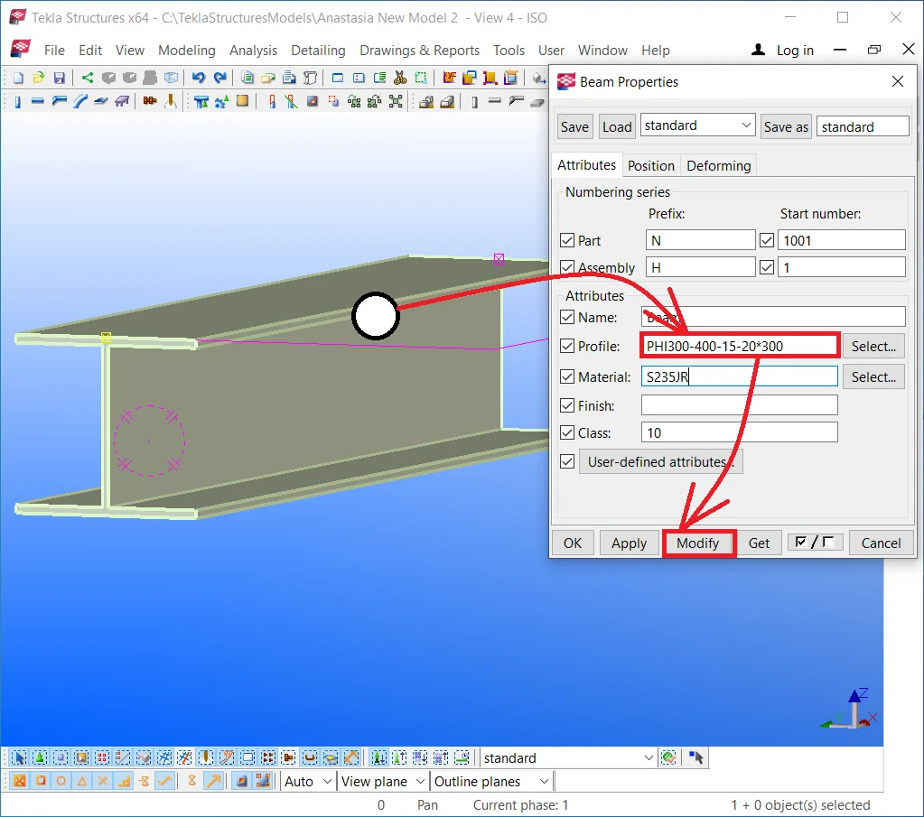
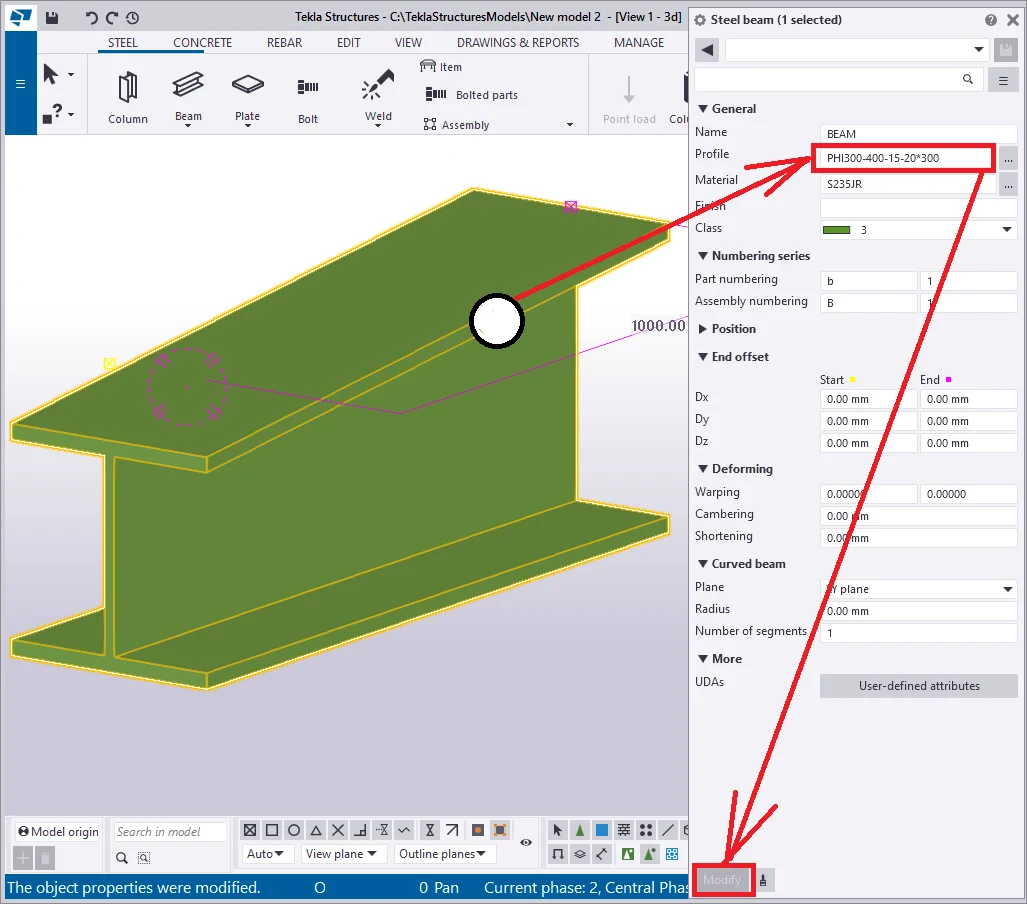
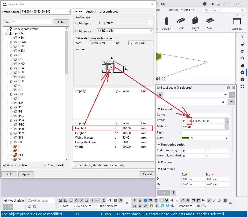
Set the beam's profile at “PHI300-400-15-20*300”.
The profile title reflects all the parameters which shape the beam and
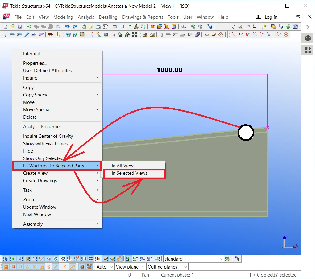
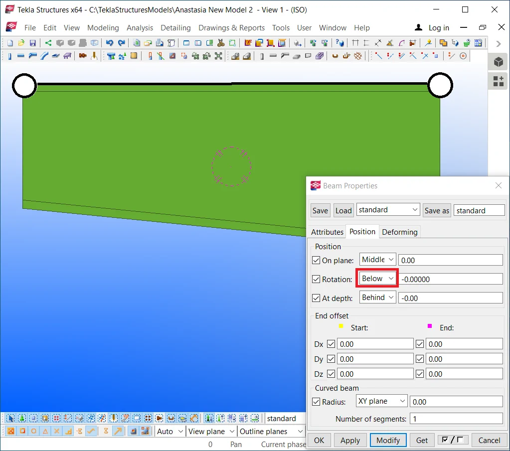
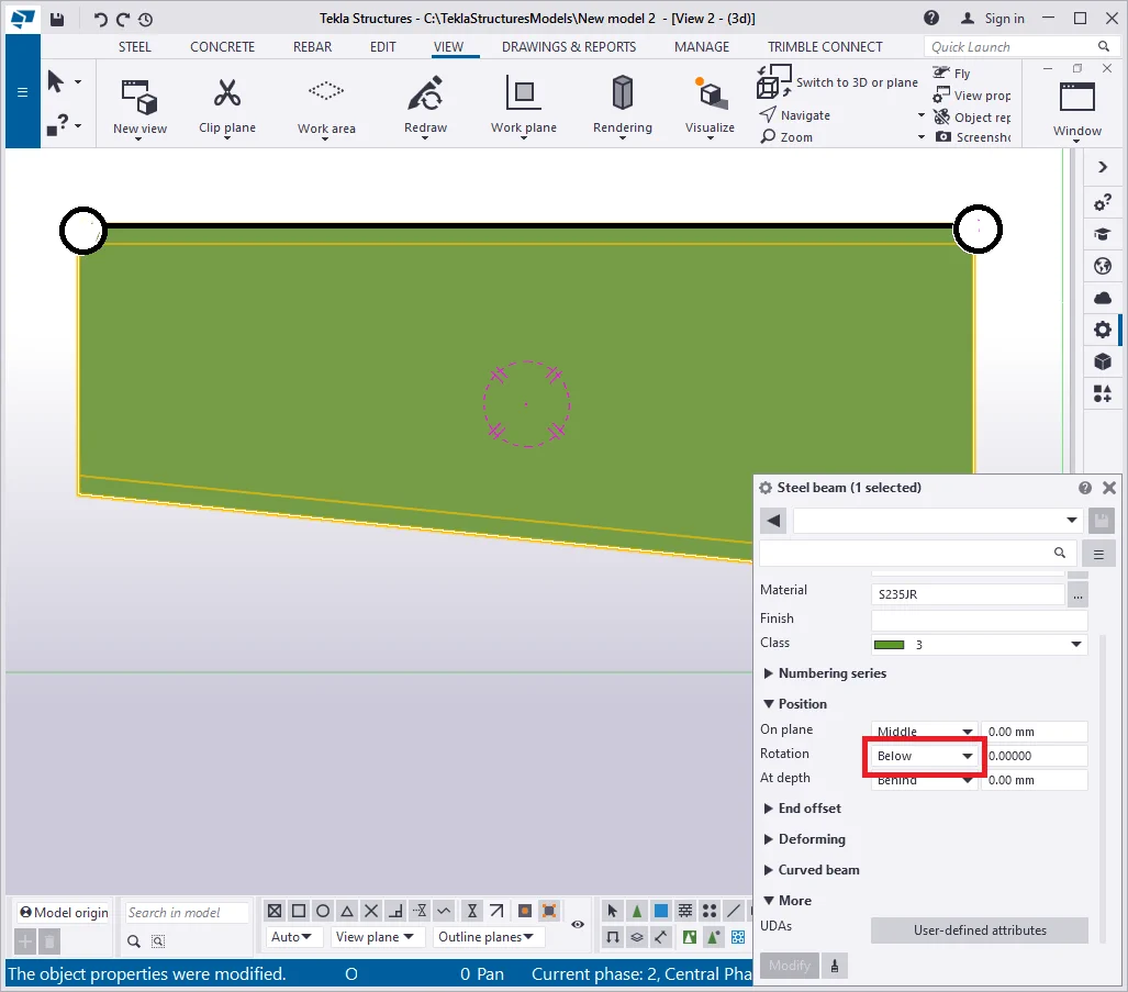
Depending on the beam's "Rotation" default settings, the real segment which we indicate, when creating a beam, can be above or below the beam's body.

Go to the 'Beam properties" menu and configure the "Rotation" parameter to the “Below”, to ensure coinciding of the building up segment with the I-beams profile straight line. Thus changing the beam’s profile will keep its top part unmoved.
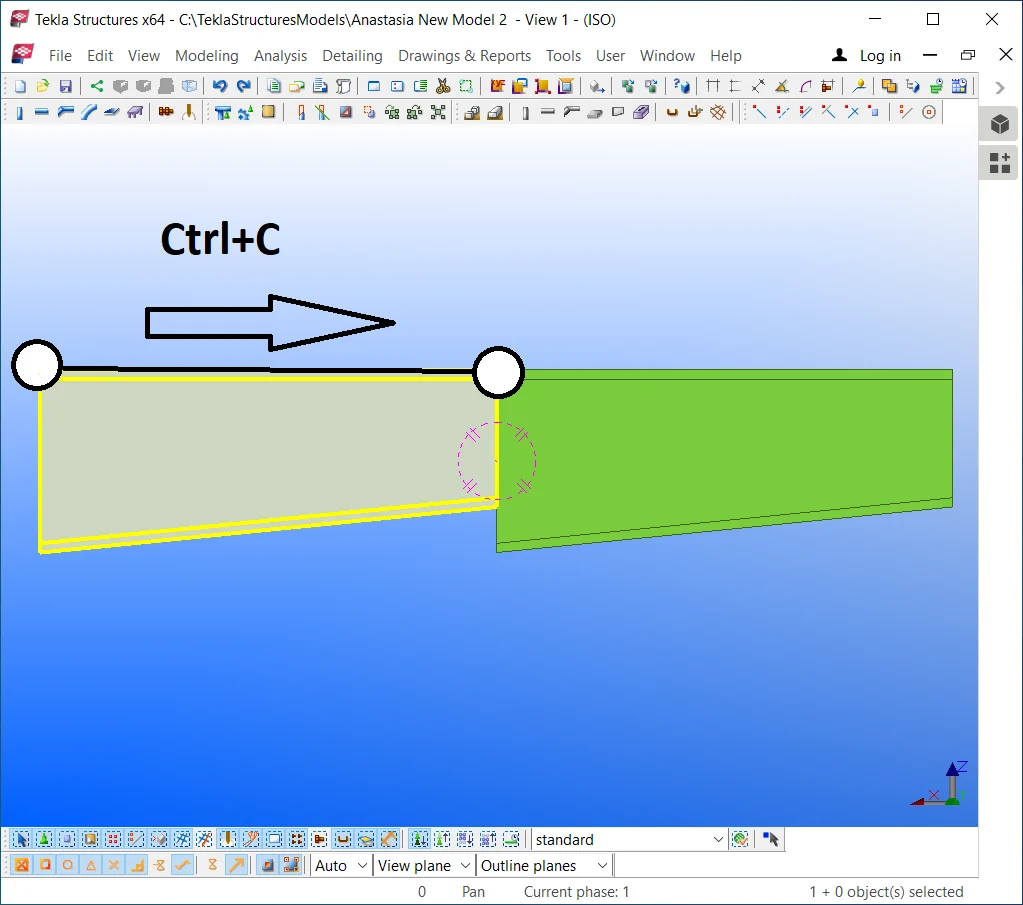
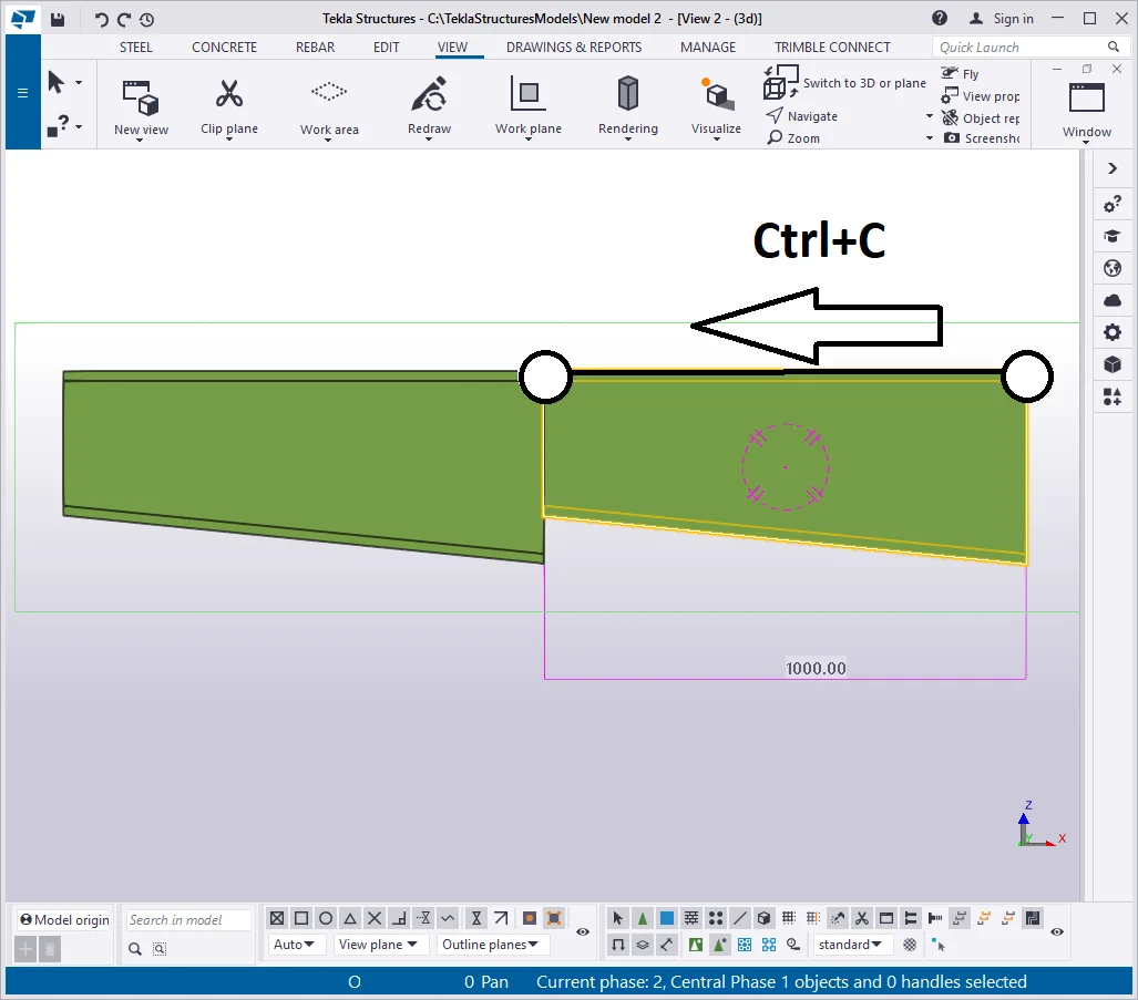
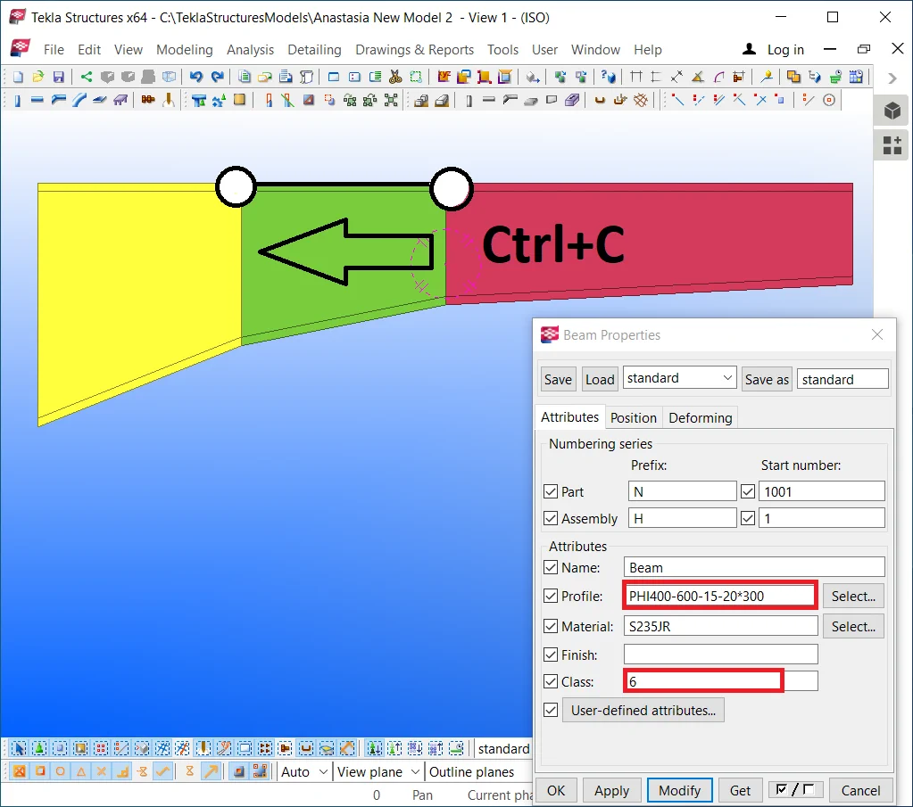
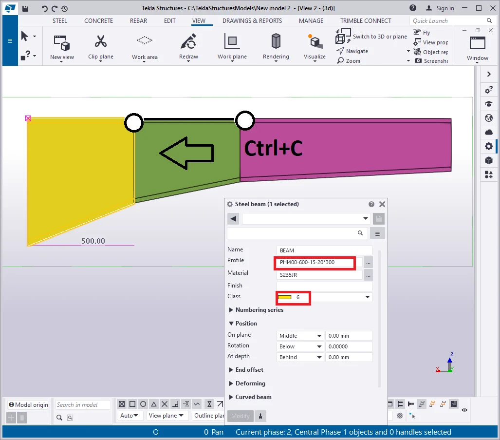
Select the beam and copy it horizontally by using the Ctrl+C hotkey combination.
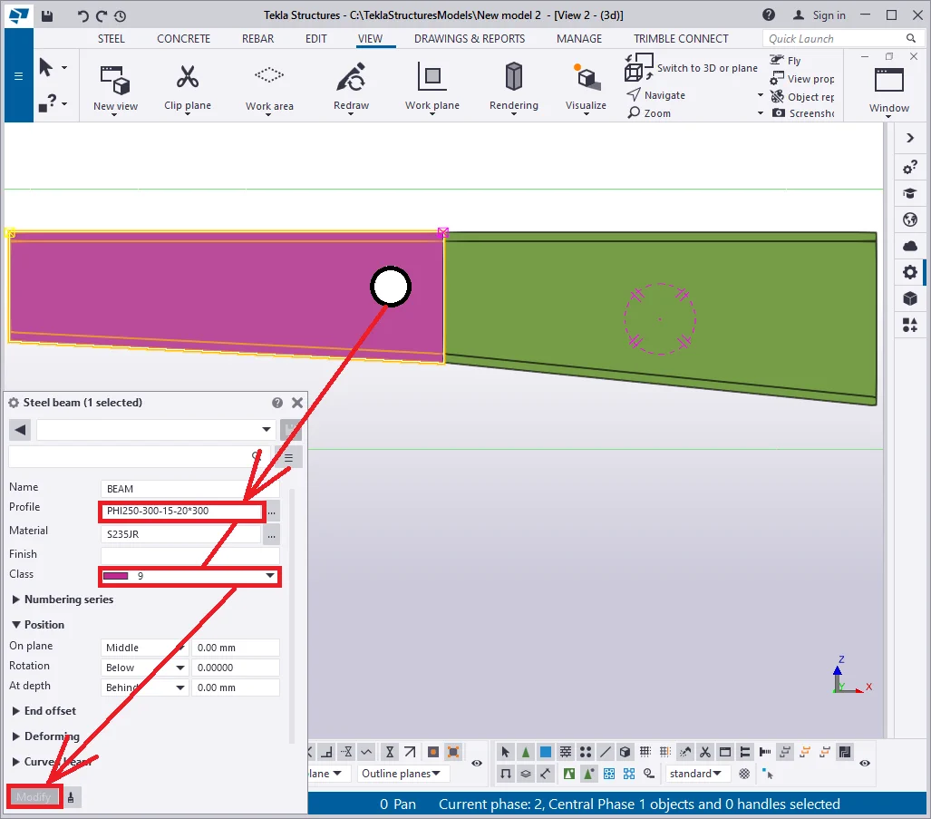
Select the new beam and adjust its profile in the way its cross-section height at the juncture point to be equal with the respective of the initial beam. Thus write in the profile type as “PHI250-300-15-20*300”, and change its class to 9, to assure better visibility between the beams.

Note that the beam's cross-section values are fixed at its starting
and endpoints, thus changing the beam’s length value does not affect
cross sections at all.
Click on the initial beam, select its right point, and by using the Ctrl+M
hotkey combination, move it to the left at 500mm.
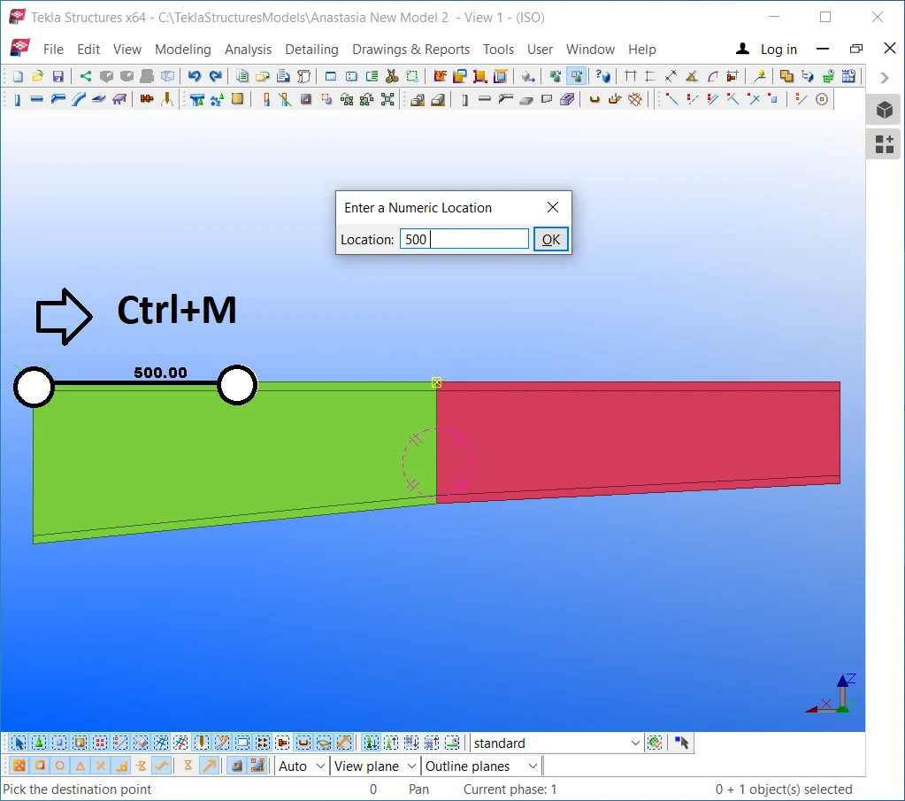
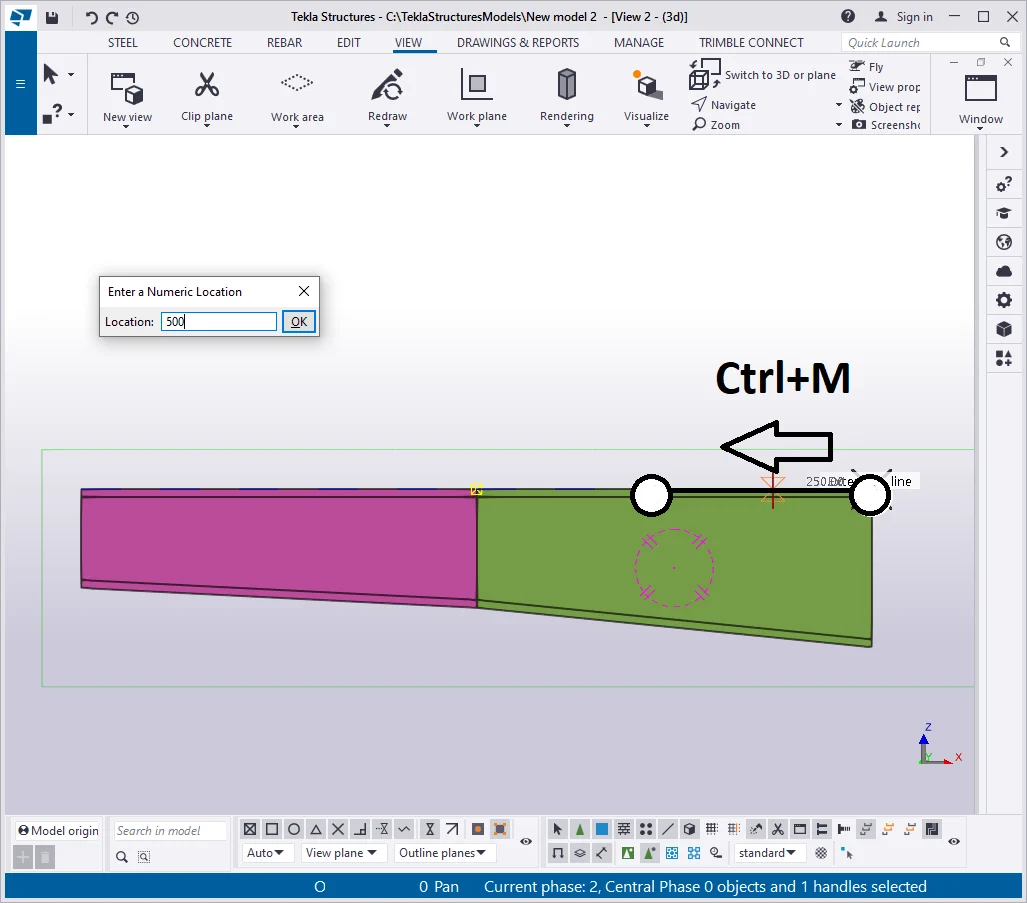
The beam has shortened, but the profile’s cross-section values remain

Copy/Paste the initial beam to the left, and configure its profile to
Advantages
Disadvantages