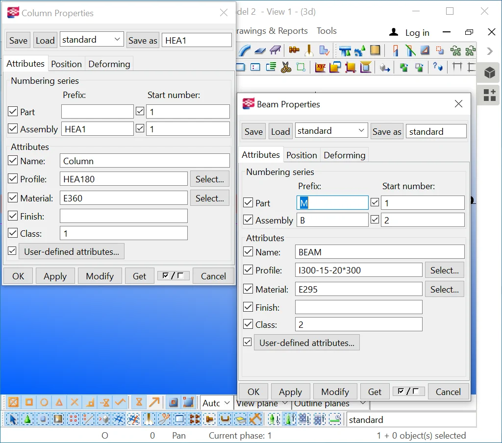
Generally, the beam and the column tools properties lists are similar,
Open the beam tool properties window. As you can see, there are a lot
of similarities among them.

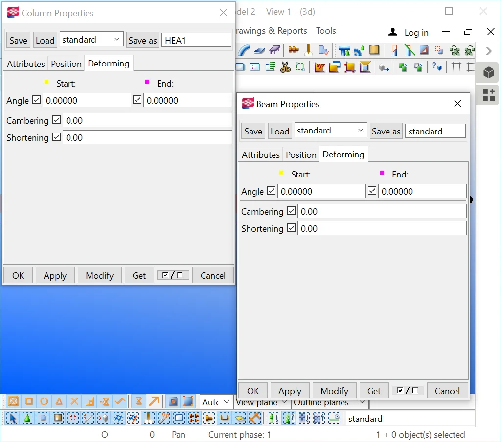
The “Deforming” section parameters are absolutely identical
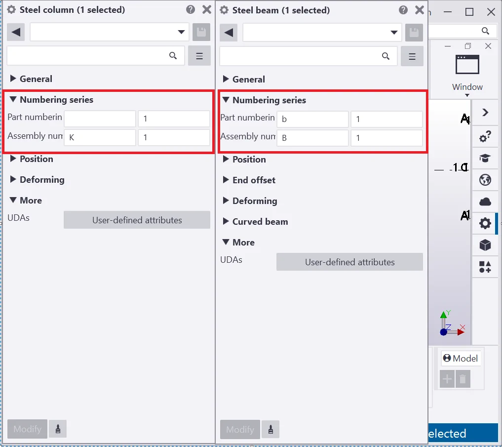
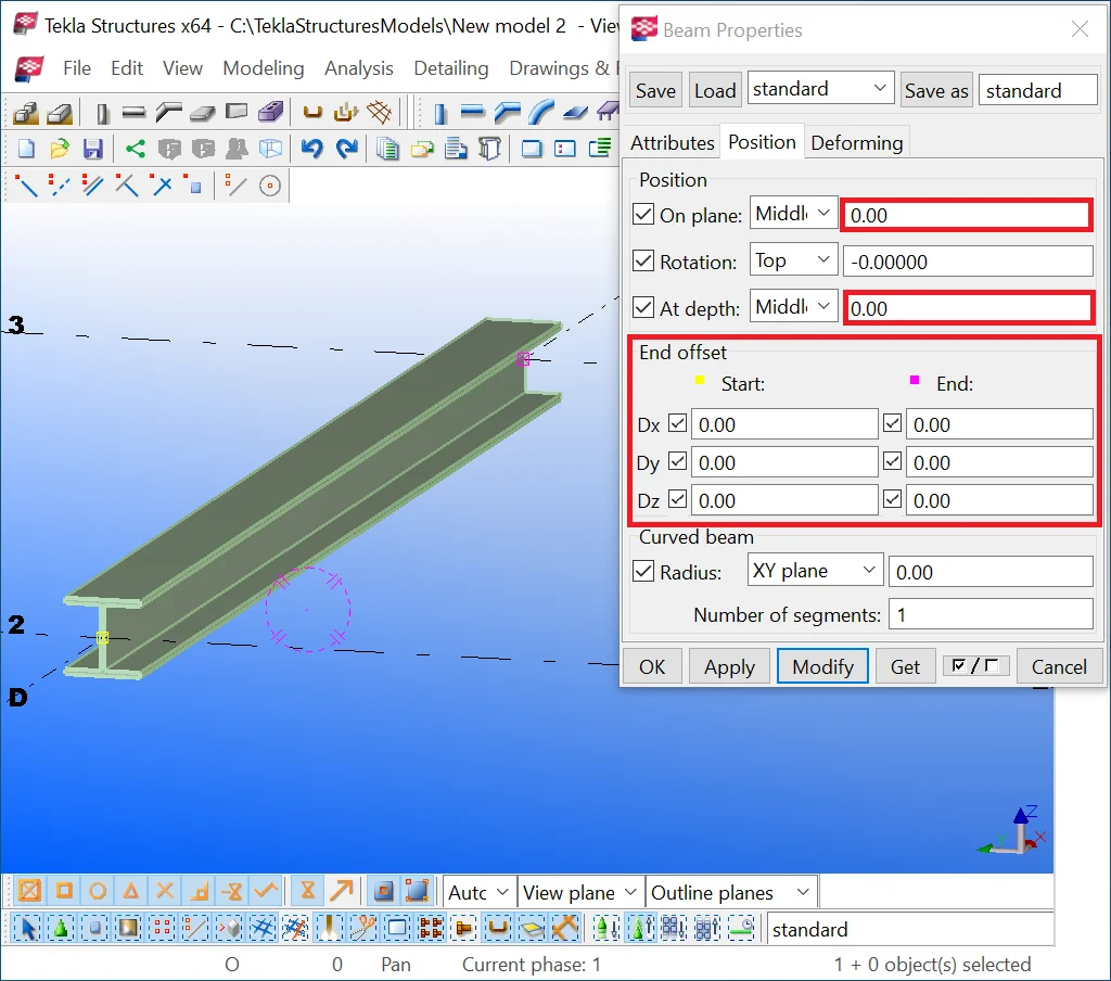
Below you can see the main distinctions between these tools framed with
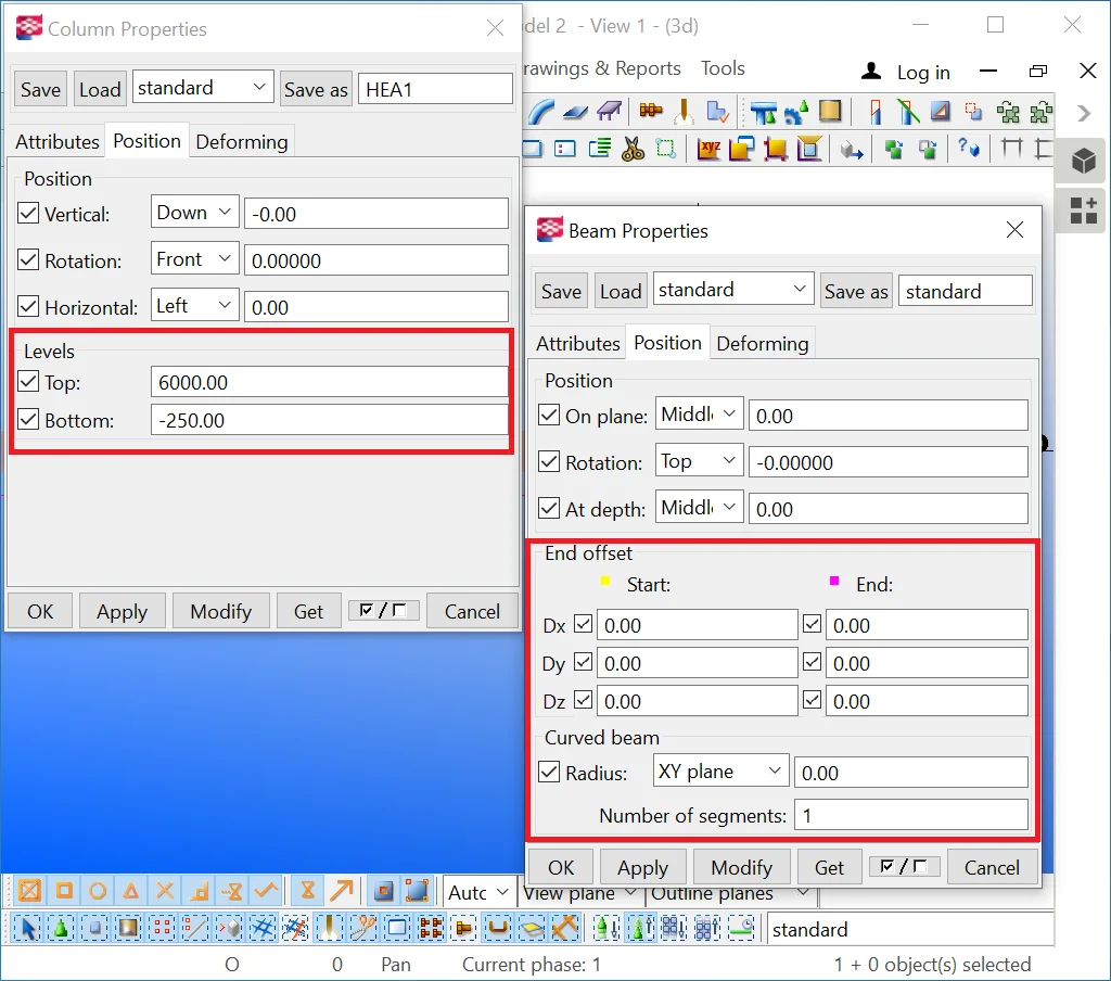
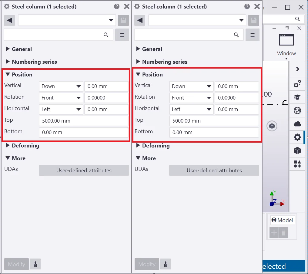
A beam may have an upright and horizontal orientation thus there are no
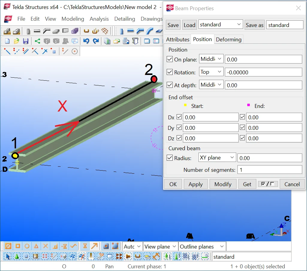
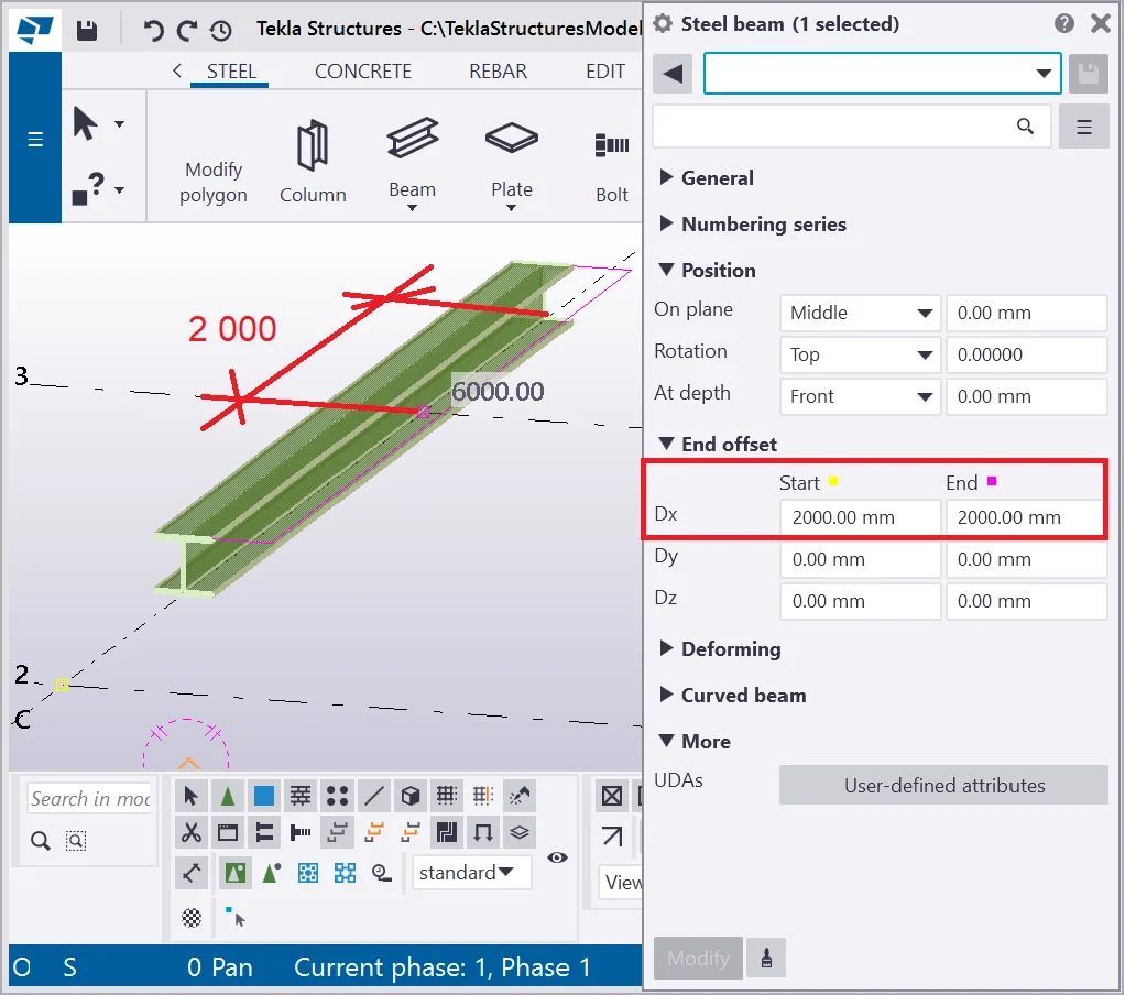
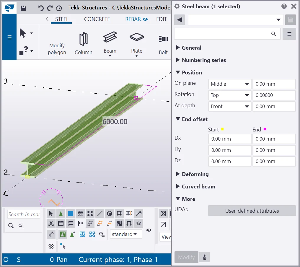
The “End offset” fields allow shifting a beam in 3 distinct directions with reference to a segment. Note that this attribute is not to be used for moving a beam. A beam itself has its local coordinate system. The X-axis is directed from point 1 to point 2, and specified by the user during drawing up a beam on the view.
The "End offset" tool can be applied for both points of a beam:

Exercise setting up the end offset value by Dx for the starting point at 2000 mm. Thus, the yellow point of the beam (starting point) shifted along the X-axis at 2000mm.
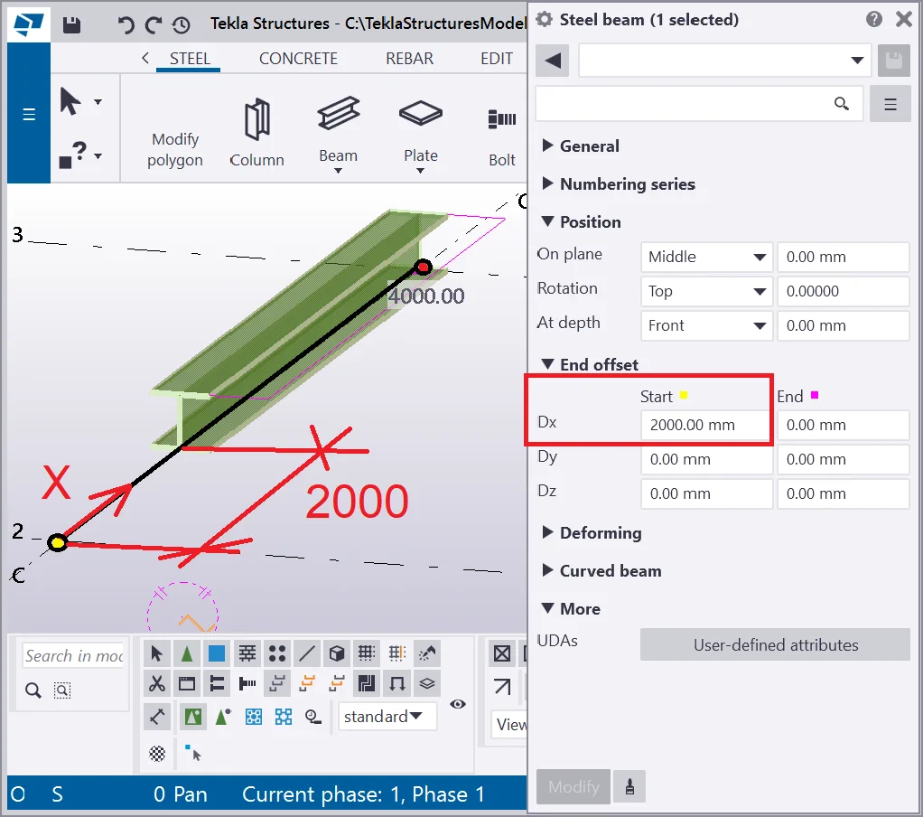
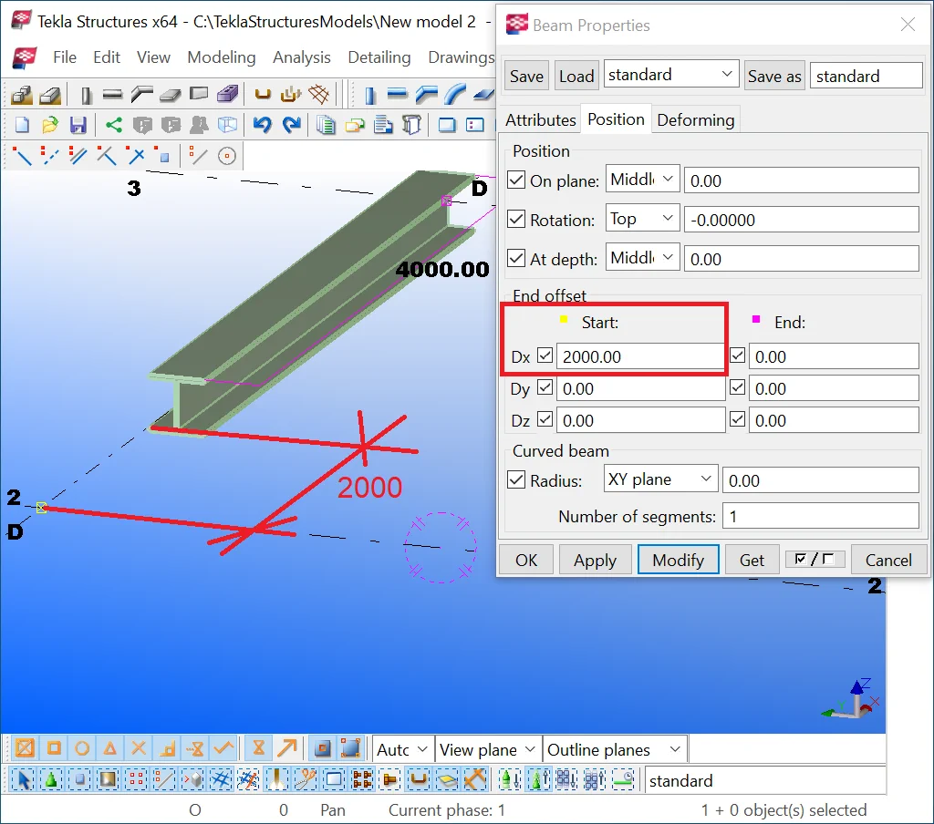
Exercise setting up the end offset value at 2000mm. Note that the point

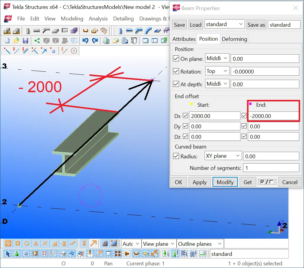
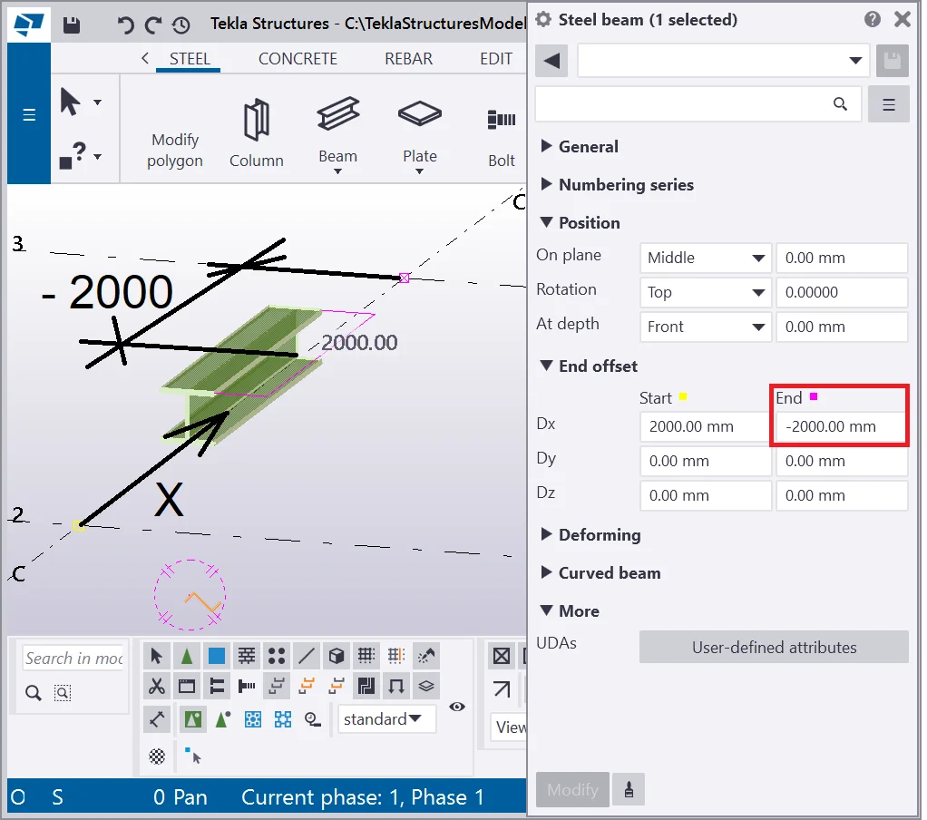
The "End offset" values can be negative thus shifting a beam
Set up the value of -2000 mm for the endpoint Dx field.
The endpoint shifted into the opposite direction of the axis X.
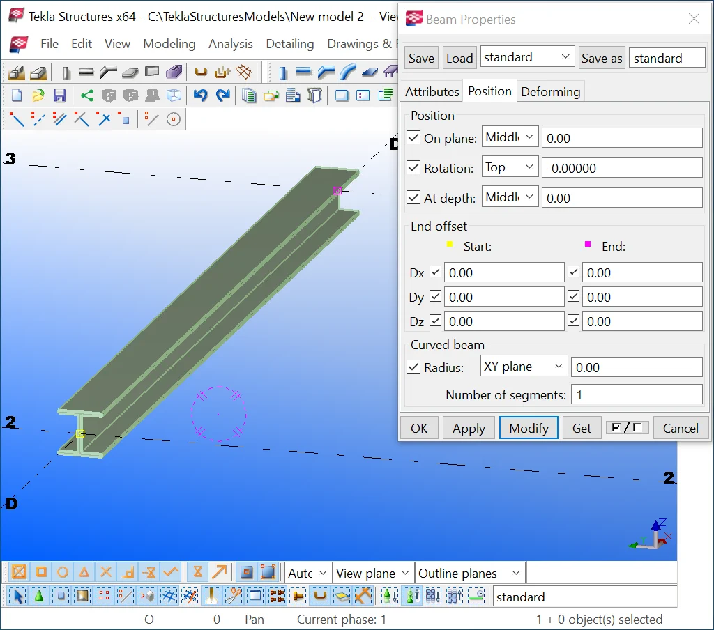
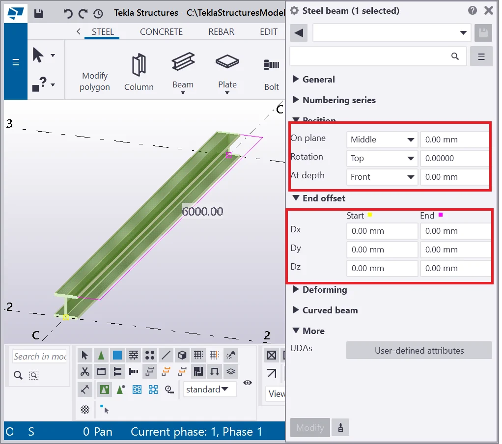
Restore the X-axis fields values to 0.
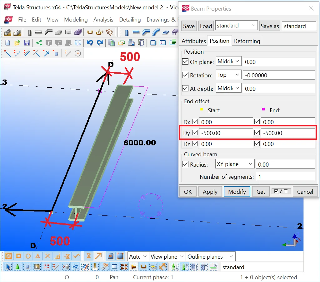
The Y-axis is constantly perpendicular to the X-axis. Set up the Dy field
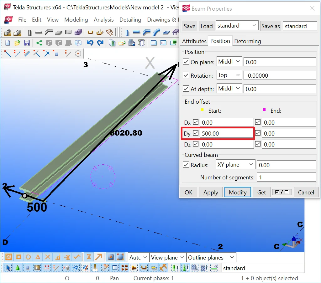
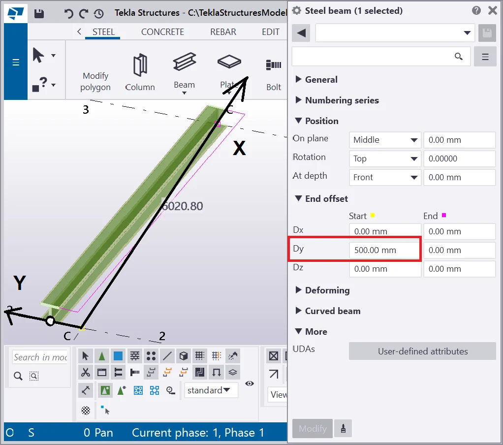
Set up the same value to the respective Dy field.

Setting up the values of the Y-axis to negative values shifts the beam

Restore the field values to 0.


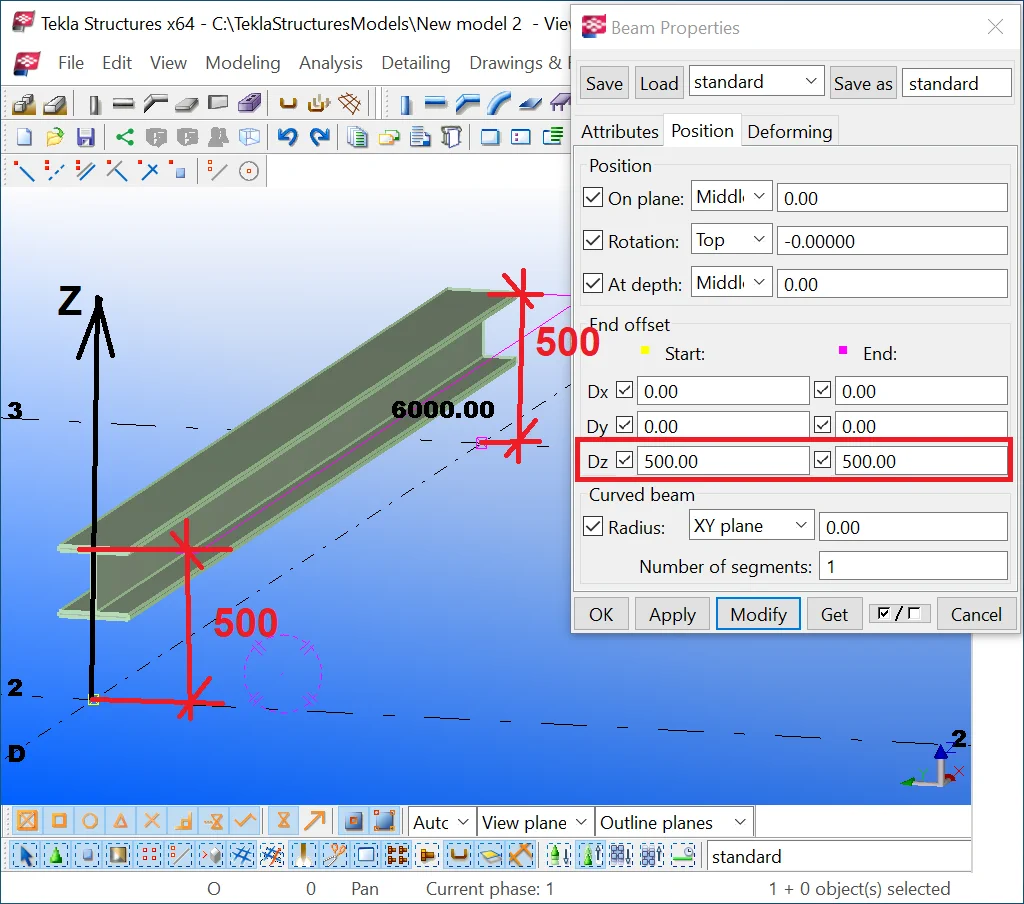
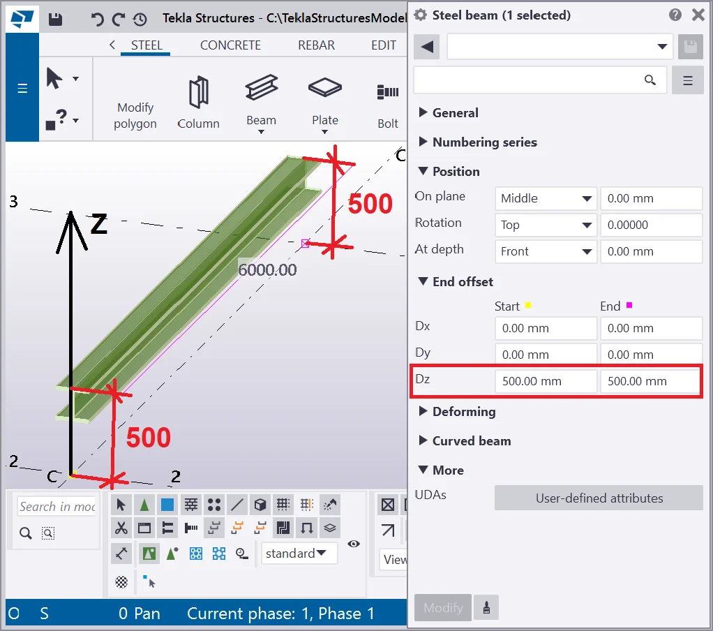
The Z-axis is perpendicular to the other axes. Set up the offset value for Dz at 1000mm.
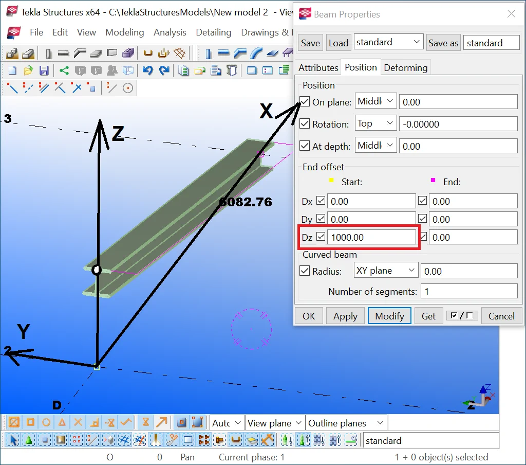
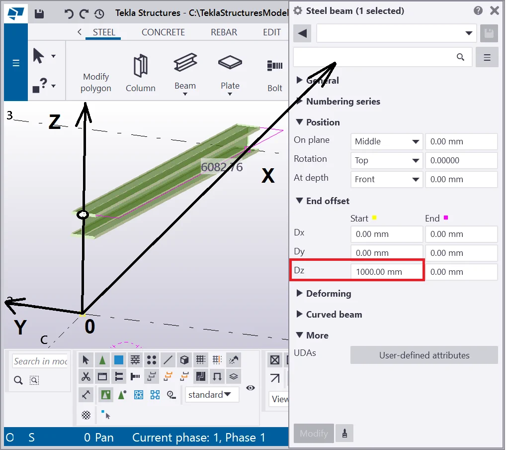
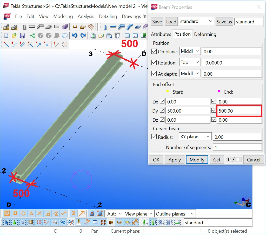
In the meantime, indicate the offset values for start and end points by
It is important to mention that essentially, the "End offset"
and the "Position" tools execute the same function, though, the
"Position" tool displaces all the points of an object simultaneously,
but the "End offset" tool executes a selective displacement of
the points.
In practice, the "End offset" tool is not of frequent use. It allows extending the beam ends, which is seldomly required, in the time when the "Position" tool allows rotating an object.
Exercise by yourself to set up various values to the “End offset”
fields to examine the tool's functioning. For further convenience,
let’s not use the "End offset" tool in the foregoing exercises.
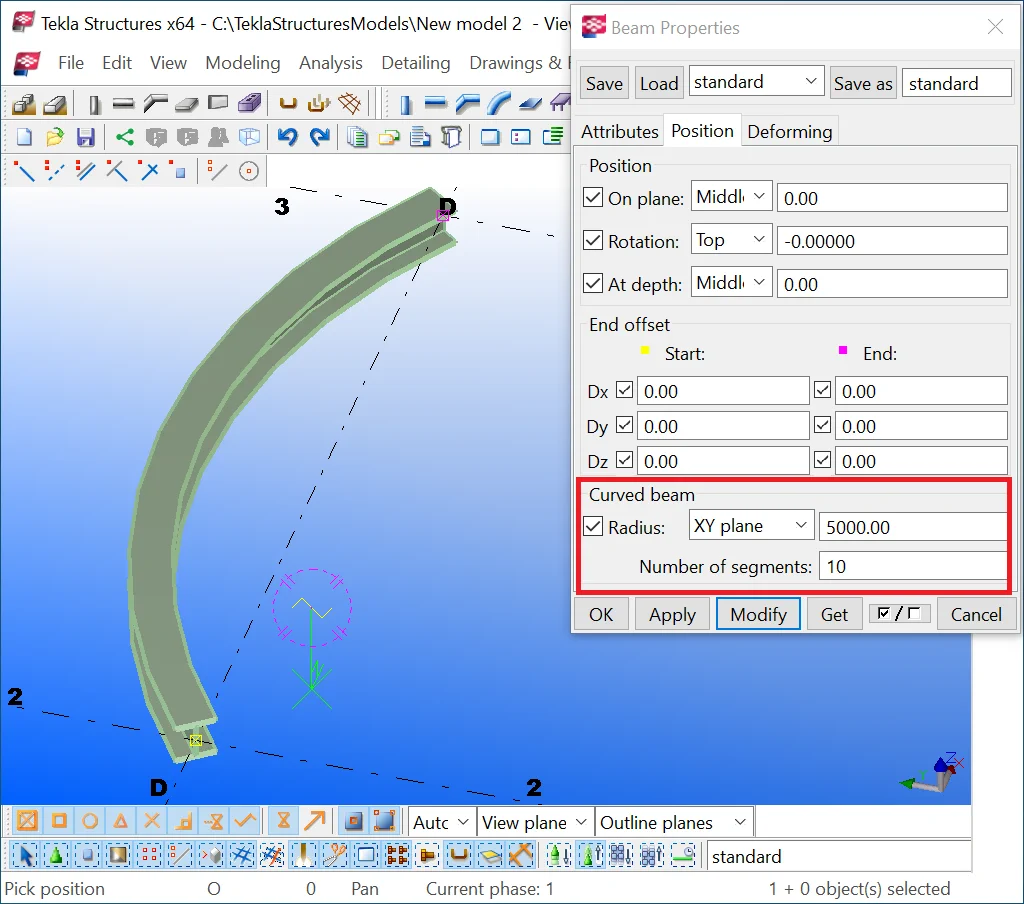
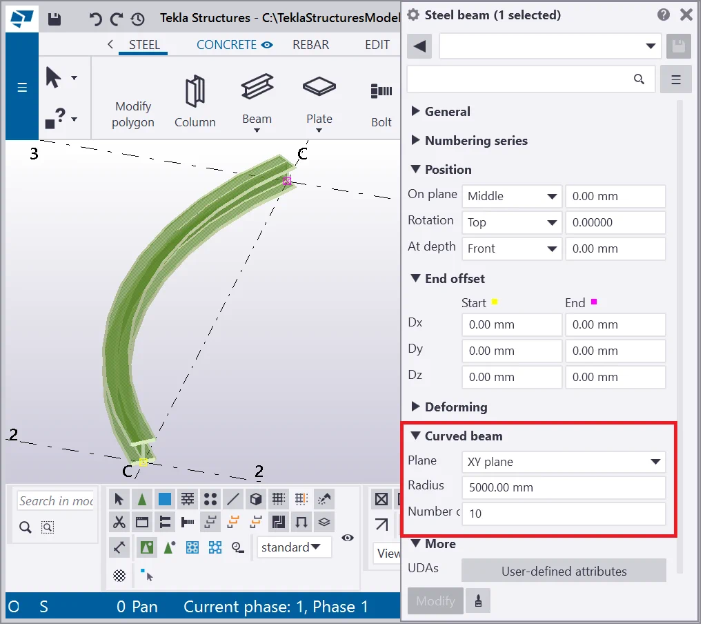
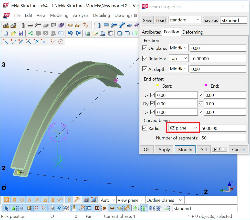
The Curved beam “Radius” and “Number of segments”
We had already examined how to camber an object in the previous chapters. Here we would like to mention that the “Radius” attribute of the “Curved beam” section also allows cambering an object by specifying the number of segments. Note, that using this attribute is reasonable just in case you are importing or exporting data from calculation programs, which allow adding intermediate points on a rod.
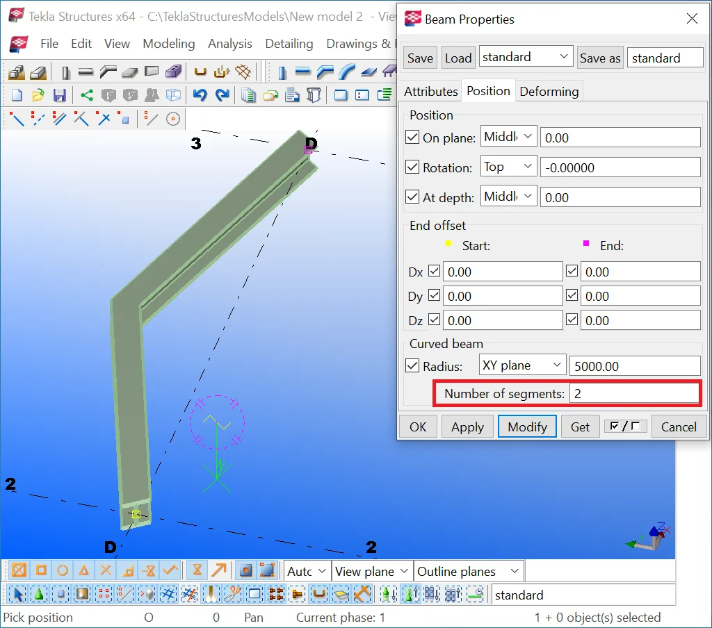
Create a beam of 6000 mm, and specify in the "Radius" field
Setting the number of segments equal to 1, makes the TS automatically convert it to 2, as if the number of segments is less than 2, then the object is a simple straight beam.
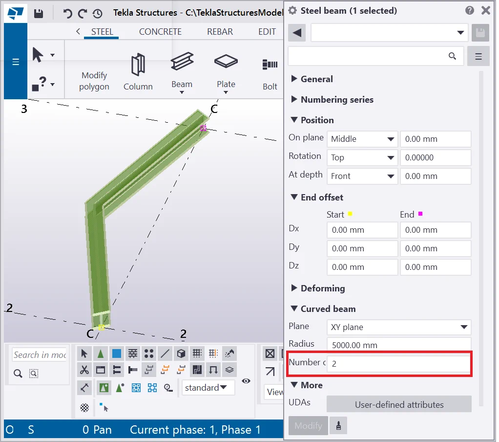
Indicate the number of segments equal to 3. Check the result. Note that in practice, this tool is not used for cambering beams.
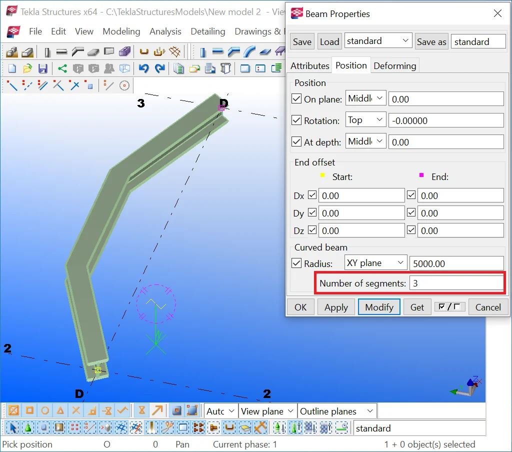

Maximizing the number of segments still does not camber the composite segments, those being straight beam fragments. But preparing models for calculation might benefit from using this tool.


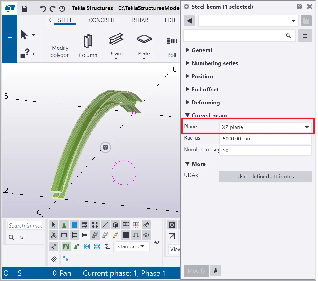
Setting up the curved beam "Plane" value cambers a beam into any direction required. Exercise all the options available in the drop-down menu of the “Plane” field.
Restore the default field values to avoid creating new beams possessing
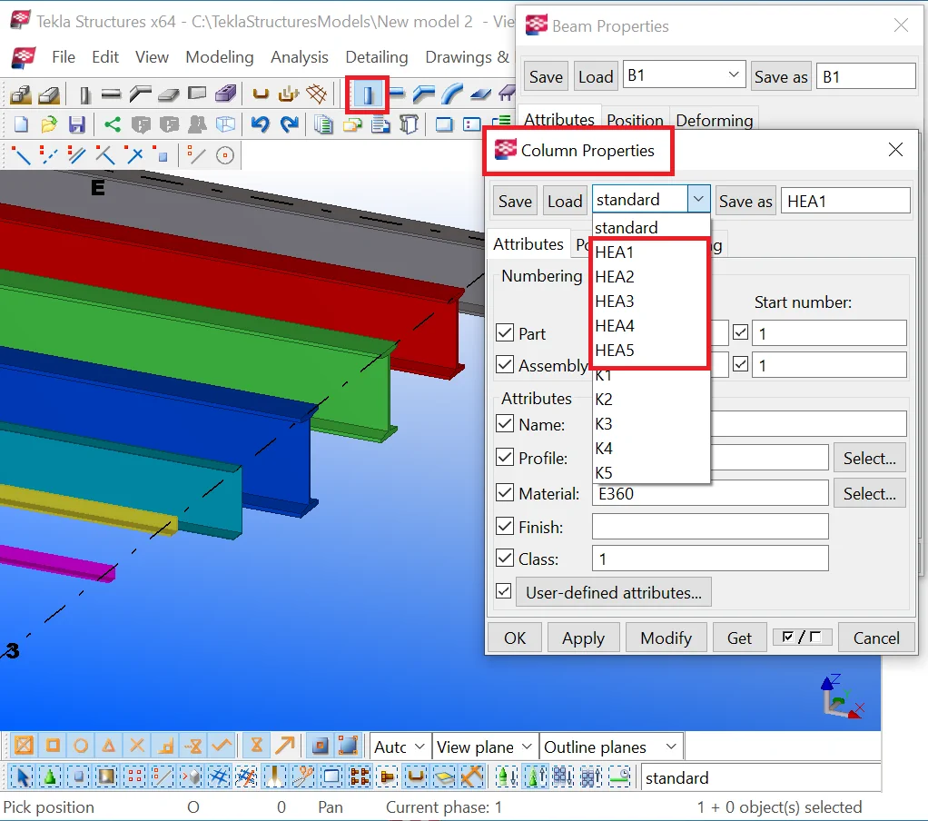
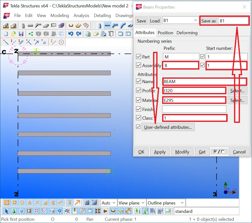
Saving the settings configurations of a beam.
Note that the saved settings configurations of the Column tool are not applicable for beams, and vice versa so far as will not be available for selection in the drop-down menu, even if the configurations titles assigned are the same.
Please configure and save the following sets of properties as specified
|
|
Parameter |
Assemblies prefix |
Profile |
Material |
Class ( color) |
|
1 |
Beam |
B1 |
I320 |
E295 |
1 |
|
2 |
Beam |
B2 |
I360 |
E295 |
2 |
|
3 |
Beam |
B3 |
I400 |
E360 |
3 |
|
4 |
Beam |
B4 |
I450 |
S235J0 |
4 |
|
5 |
Girder |
G1 |
MET-CS302 |
E295 |
5 |
|
6 |
Brace |
Br1 |
L65*7 |
E360 |
6 |
|
7 |
Brace |
Br2 |
L55*6 |
E360 |
7 |
Introduce the table data into the respective fields, specify the titles
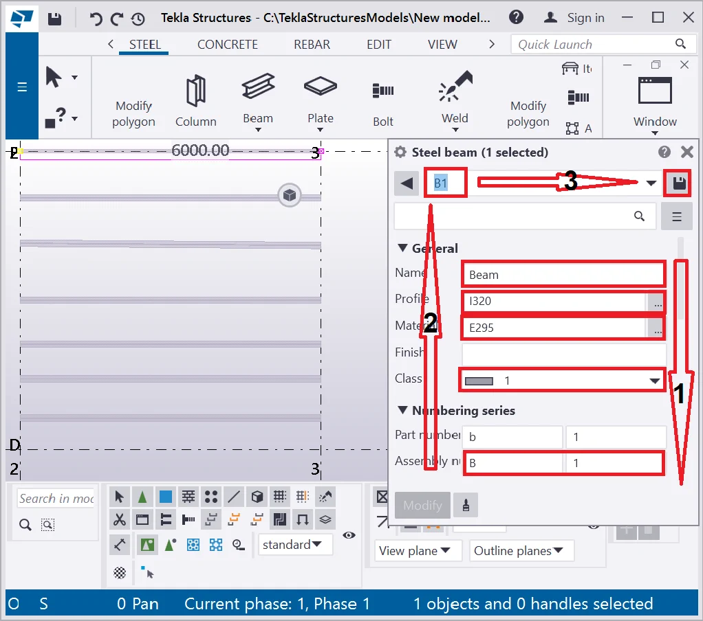
When done, check if the “Object type” drop-down list is available


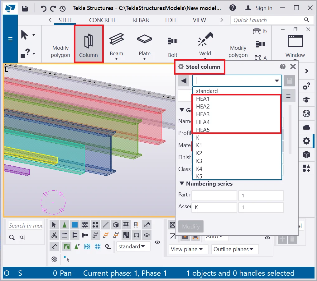
Open the “Steel column properties” window and make sure that there is no intersection with the “Beam properties” saved settings list.