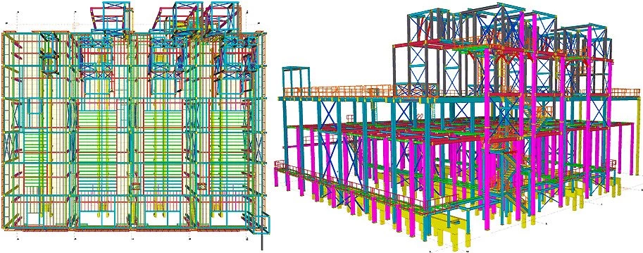
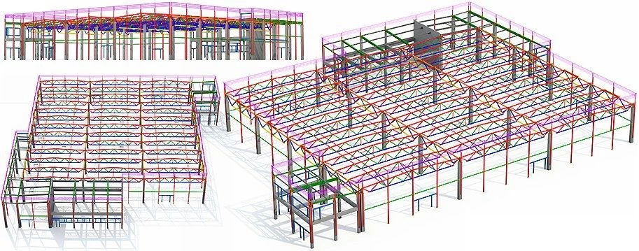
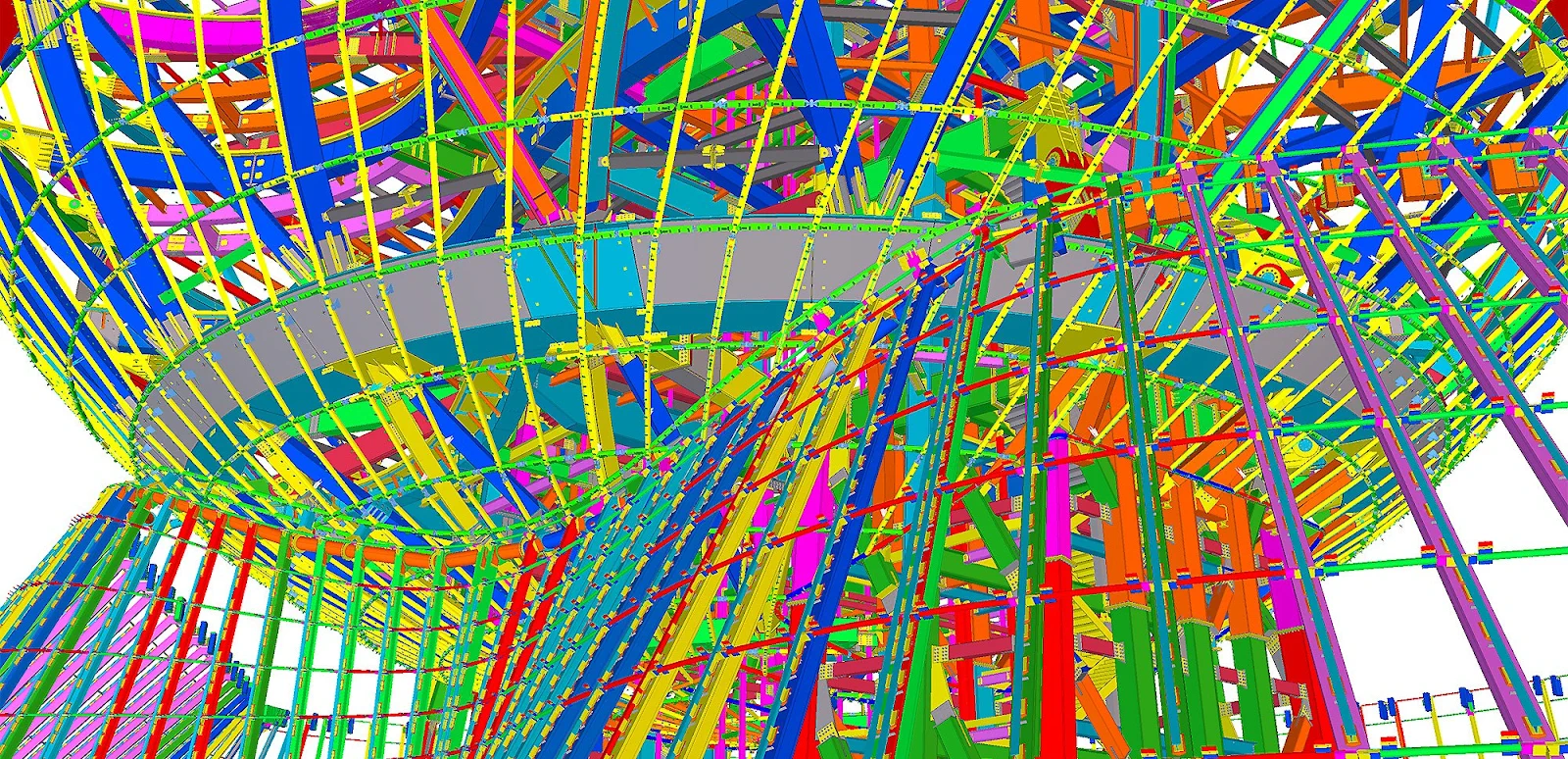
The "Deforming" tool is used for creating objects with complex geometry. Below you can see the example of a complex structure composed of warped and cambered columns.
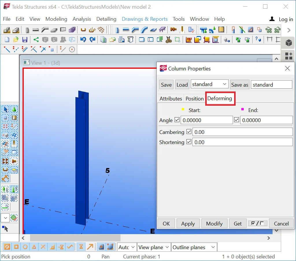
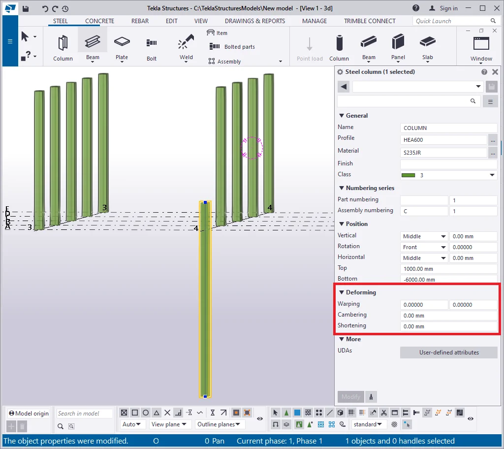
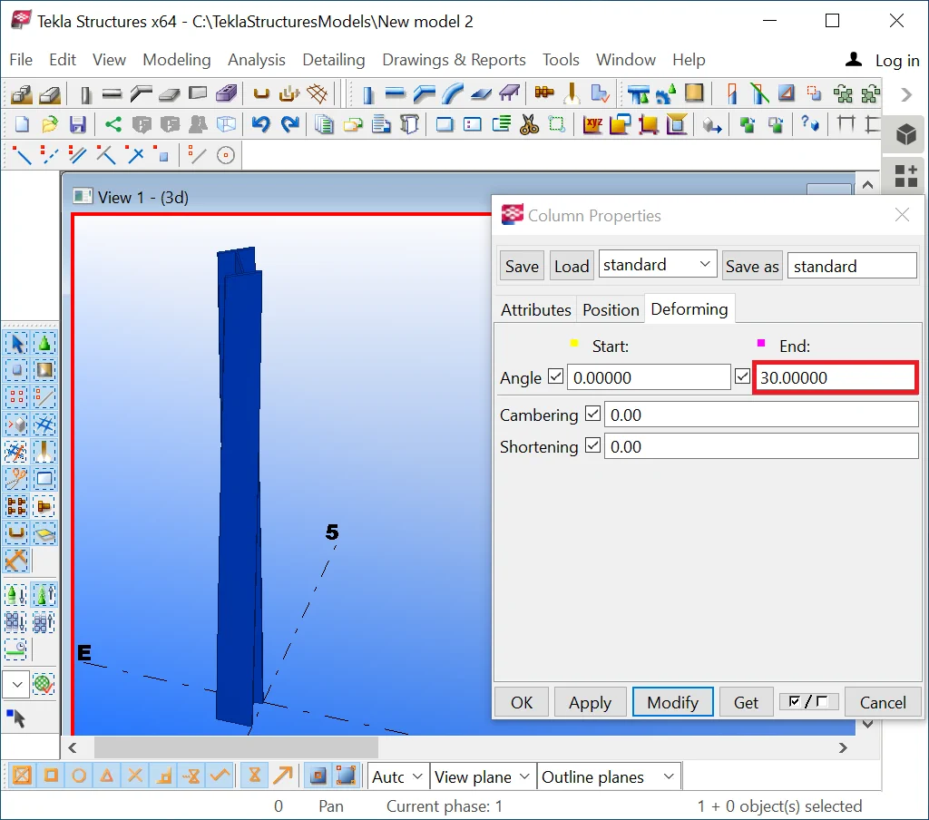
Go to the “Deforming” section of the “Column Properties”
menu. Note that all default values of the parameters are set at 0.
Let’s examine the subfields of the "Deforming" menu section. The “Warping” field coils a column in a spiral. By default, the warping value equals 0, but it can be set up to any value.
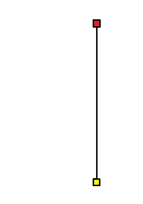
As we already know, each column is defined by a starting (marked in yellow)
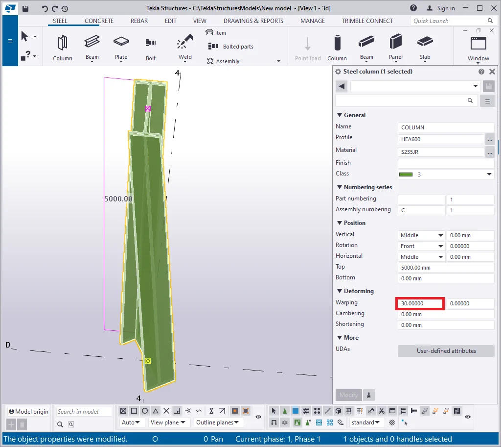
The "Warping" field has two respective boxes for valuing these points. To warp a column from its up point downwards is realized by specifying the warp angle of the endpoint into the respective box, e.g. 30 degrees. Check it out.


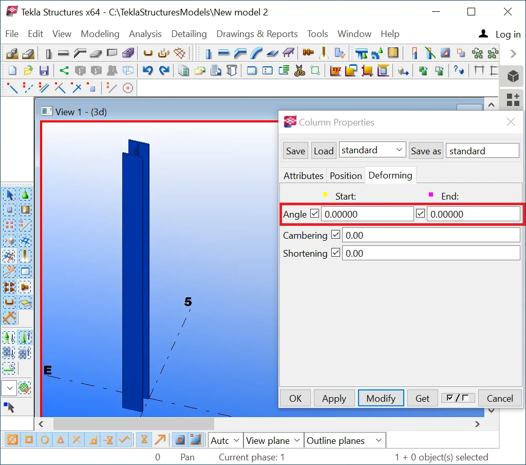
To warp the column from its endpoint, by leaving the column top side static,
specify the 0 value at the endpoint field, and the value of 30 degrees
at the starting point field.
Consider that indicating a warping value over 360 degrees coils the column in the numerous spins. In real practice, such examples are rarely met, except for mechanical engineering.
Try out editing the warping angle for the end column point.

Upon completion, restore all the “Warping” field values to 0.

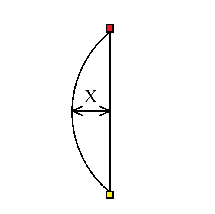
The “Cambering” tool twists (curves) a column.
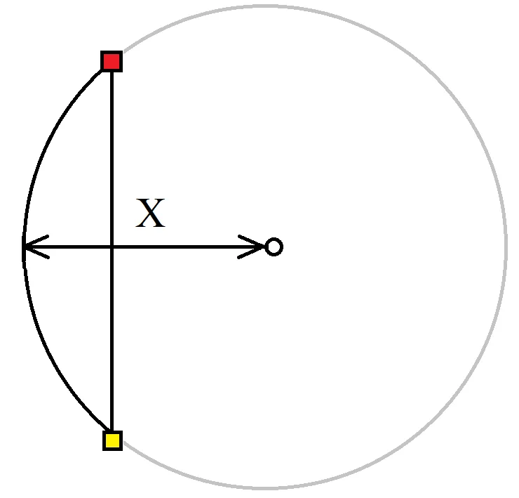
It is composed of two coherent basic parameters which make a column’s body cambered: the bending off parameter and the radius of the circumference on which the column is to be situated.
If the value indicated into the field is less or equal to one-half of the column’s length, then TS accepts this value as the bending off parameter, otherwise it automatically considers the value as the circle radius. The cambering direction is set up by indicating one of the symbols “+/-”.
|
Cambering value =0 |
Cambering value <= ½ column length |
Cambering value >= ½ column length |
|
|
|
|
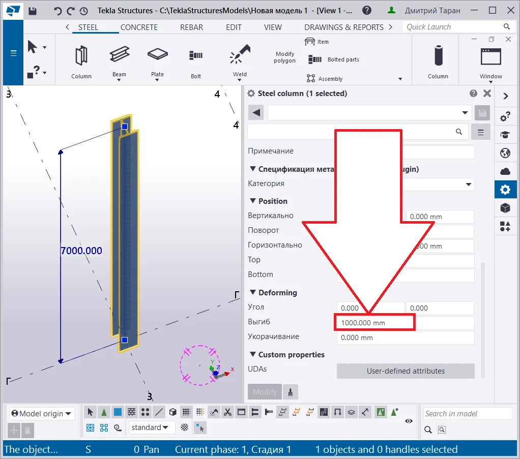
Let’s exercise cambering a column by introducing a cambering value
In the new Tekla Structures interface the cambering field is not functioning.
However, uploading models created using previous TS versions may solve the issue and reflect cambered objects correctly, though modifying the uploaded data still remains impossible.
We do suppose that these fields are necessary for assuring compatibility with the older TS versions.
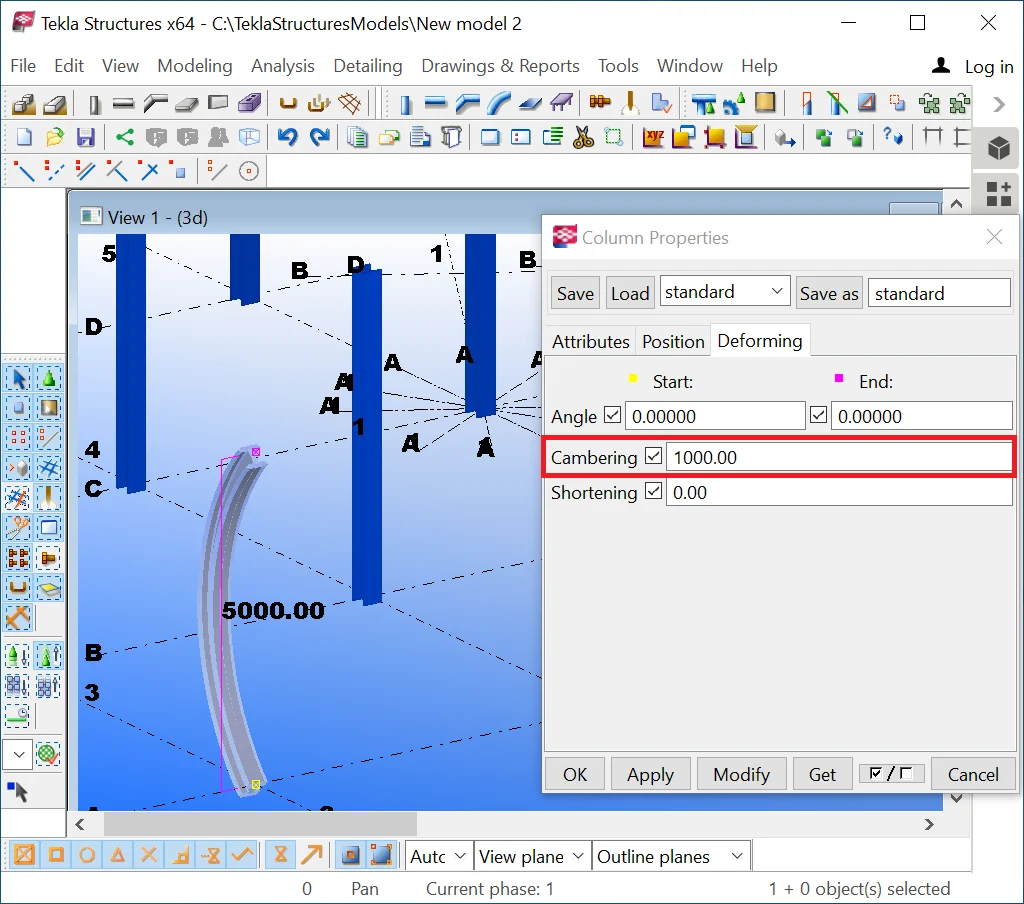
Now, set up the cambering value exceeding one-half of the column length,
e.g. 10000 mm. TS will automatically define it as a part of the circumference
length with radius of 10 000 mm, resulting from intersection of the circumference
with the initial column-bisecant. Compare your results to the below:
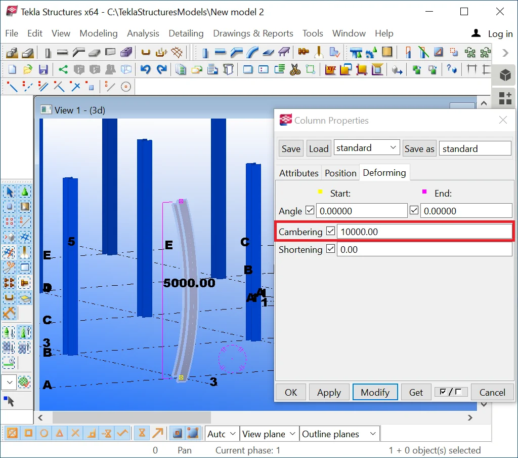
In the new Tekla Structures versions the “Cambering” field is not functioning.
Restore the field values to their default settings. The “Shortening” tool is the one seldomly used. It simultaneously brings up different values of the same parameter into the statement and the drawing specification.

In the new Tekla Structures versions the “Cambering” field is not functioning.
This tool is mostly applicable when modeling reduced plates.
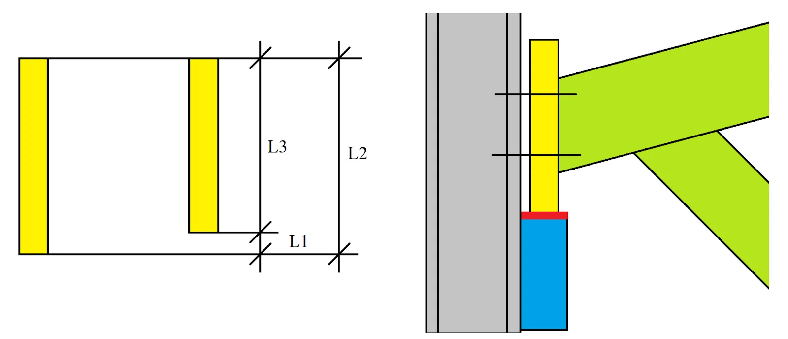
For example, a bearing plate is welded on to the formwork’s edge, thus it has to be reduced for obtaining a plane surface. Bearing surfaces must be critically plane (see marked with red in the above picture). That is why an already manufactured and welded-on component is additionally reduced, defining a decrease of the initial plate’s width value.
Exactly this fact brings up the issue of how to reflect the component in the drawing. If we draft the part with no concern to reduction, the geometry of the part intersects with the geometry of the structure.
If we reflect the part with its reduced thickness value, the statement for manufacturing pre order indicates the dimensions of the part without considering the allowance for reducing, thus the manufactured component is too low.
Such wise the "Shortening" field specifies the thickness of
the bearing plate prior to reducing, indicating the value to be included
into the preorder report, and at the same time, it reflects the thickness
of the bearing plate to be reflected in the drawing.
|
Shortening (L1) |
Component dimensions at the drawing (L2) |
Component dimensions included in the preorder report (L3) |
|
0 |
5500 |
5500 |
|
1000 |
5500 |
4500 |
|
-1000 |
5500 |
6500 |
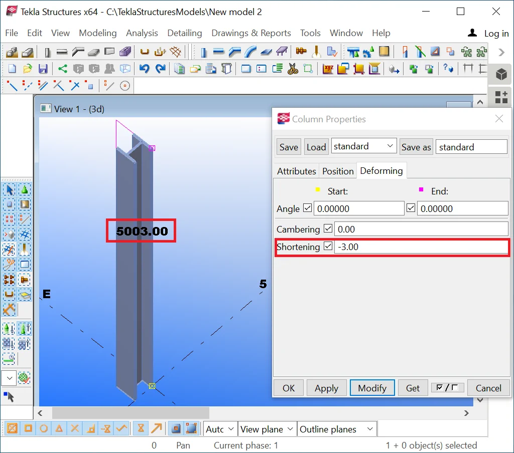
Exercise introducing various values into the "Shortening" field,
e.g. 1000 and -1000. Note that the geometry of the model does not
change after executing shortening, but when selecting the object, the TS
displays different values of the dimensions of the objects at the drawing
and in the statement.
The allowance for reducing is defined by the range of 2-6 mm and depends on various factors. Thus in the report it is reasonable to indicate the thickness value considering the allowance for reducing, as the abatements from the drawings can be fixed outright at the construction site.
is not functioning.
Upon completion restore the field values to their default settings.