Kosovska 17, Beograd-stari grad, Serbia
+3 816 161 39 37 0
info@top-engineer.com
HOME
STEEL DETALING
REBAR DETALING
BIM MODELING
METALIB
Introduction
1.1 Who can benefit from studying present guidelines
1.2 Tekla Structures features map and application fields
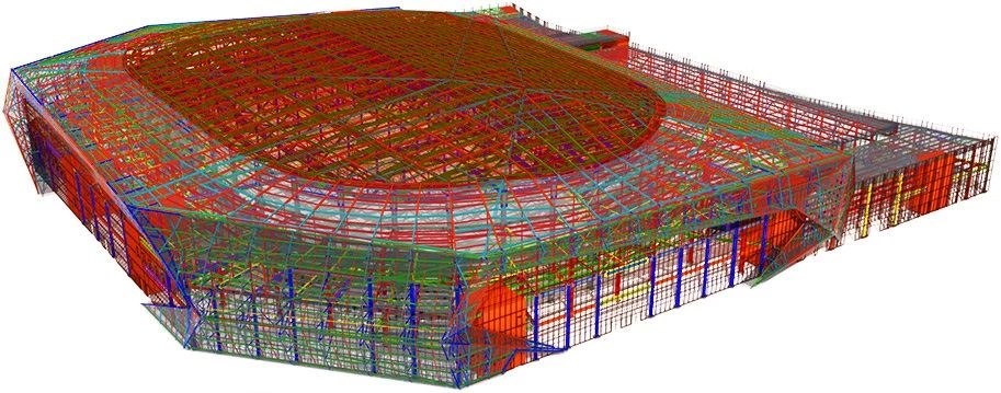
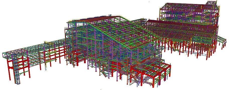
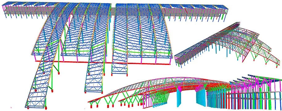
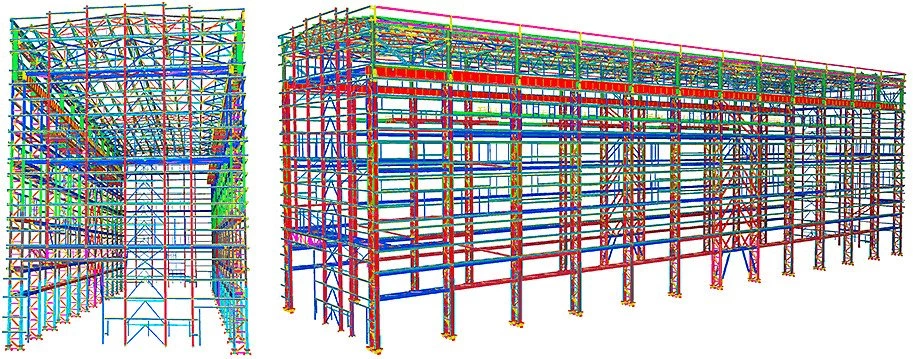
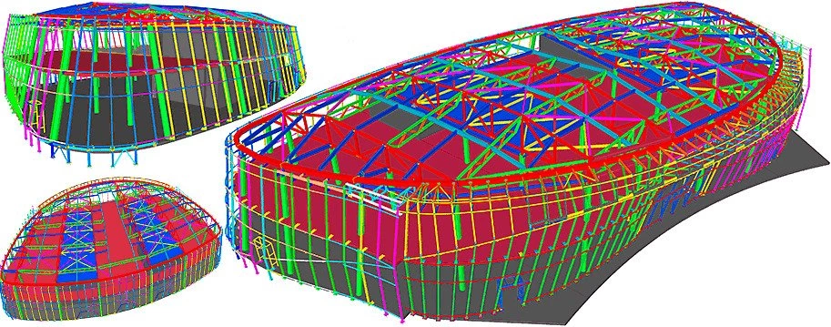
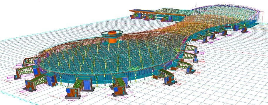
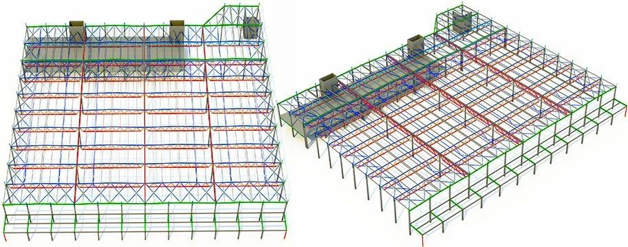
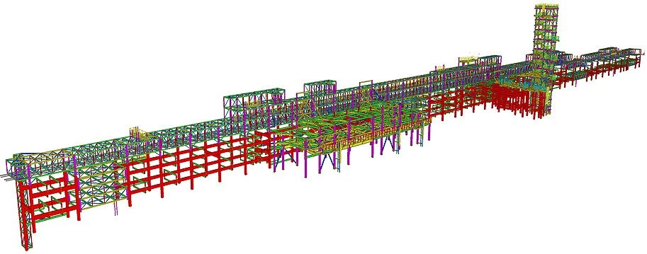
1.3 Field cases executed in Tekla Structures
1.4 PC System requirements for using the Tekla Structures
1.5 Where to download the Tekla Structures training version
1.6 Tekla Structures installation tips
1.7 Tekla Structures localization packages
1.8 Launching Tekla Structures
First step *
2.1.1 Creating a new project
2.1.2 The main menu elements in Tekla Structures
2.1.3 Minimizing/ maximizing the model in Tekla Structures
2.1.4 Rotating a model in Tekla Structures
2.1.5 Creating standard views in the model by XY, XZ, ZY axes in Tekla Structures
2.1.6 Arranging/switching views in Tekla Structures
2.1.7 Switching to the view plane in Tekla Structures
2.1.8 Dragging the view plane in Tekla Structures
The “Grid” tool
2.2 The “Grid” tool in Tekla Structures
2.2.2 The “Modify” button of the Tekla Structures “Grid properties”
2.2.3 Creating a complementary grid in Tekla Structures
2.2.4 Saving the current grid settings in Tekla Structures
2.2.5 Uploading the saved grids configurations into other Tekla Structures models
2.2.6 Setting out the snapping tools
2.2.7 Moving grids in Tekla Structures
2.2.8 Copying a grid in Tekla Structures
2.2.9 The “Radial grid” tool in Tekla Structures
Steel columns
2.3 Steel columns in Tekla Structures
2.3.1 Creating columns in Tekla Structures
2.3.2 The “Column Properties” menu in Tekla Structures
2.3.3 The “Cancel” and “Close” buttons in Tekla Structures
2.3.4 The “Apply” button in Tekla Structures
2.3.5 The “Ok” button and its main distinctions from the “Cancel”
2.3.6 The “Get” button in Tekla Structures
2.3.7 The “Modify” button in Tekla Structures
2.3.8 The position of a column in Tekla Structures
2.3.9 The “Deforming” tool of the “Column Properties”
2.3.10 Simultaneously setting up particular attributes in Tekla Structures
2.3.11 The “Save settings” box in Tekla Structures
2.3.12 The “User-defined attributes” of the “Column
2.3.13 The “Mini toolbar” in Tekla Structures
Snapping tools/ Selecting tools/
2.4 Snapping tools/ Selecting tools/ Object types in Tekla Structures
2.4.1 Selecting and ignoring objects by type
2.4.2 Snapping an object to the geometry
2.4.3 Snapping to the object reference/corner points
2.4.4 Selecting objects by frame in the left-to-right and right-to-left direction
The Construction geometry
2.5 The “Construction geometry” tools in Tekla Structures
2.5.1 The “Points” tool in Tekla Structures
2.5.2 The “Construction line” tool in Tekla Structures
2.5.3 The "Orthogonal regime" in Tekla Structures
2.5.4 The "Construction circle" tool in Tekla Structures
2.5.5 Dividing a construction line into a specified number of segments
2.5.6 The “Construction plane” tool in Tekla Structures
2.5.7 Other construction geometry tools in Tekla Structures
The Contour plate
2.6 The “Contour plate” tool in Tekla Structures
2.6.1 Create contour plate in Tekla Structures
2.6.2 The “Contour plate Properties” menu in Tekla Structures
2.6.3 Selecting a point from the contour plate surface in Tekla Structures
2.6.4 Chamfers of a contour plate object in Tekla Structures
2.6.5 Selecting a group of points at a contour plate in Tekla Structures
2.6.6 Moving a group of points in Tekla Structures
2.6.7 Adding and deleting points at/from the contour plate in Tekla Structures
2.6.8 Creating a base plate
2.6.9 The “Cylindrical bend plate” tool in Tekla Structures
2.6.10 The “Conical bent plate”tool in Tekla Structures
2.6.11 The “Stand-alone bent plate” tool in Tekla Structures
2.6.12 The “Lofted plate” tool in Tekla Structures
The Steel Beam tool
2.7 The “Steel Beam” tool in Tekla Structures
2.7.1 Creating beams in Tekla Structures
2.7.2 Distinctions between a column and a beam in Tekla Structures
2.7.3 Transforming a beam into a column and vice versa
2.7.4 The “Polybeam” tool in Tekla Structures
2.7.5 Curved beam in Tekla Structures
2.7.6 The “Twin profile” tool in Tekla Structures
2.7.7 The “Split” and “Combine” tools in Tekla Structures
2.7.8 The “Orthogonal beam” tool in Tekla Structures
2.7.9 The “Spiral beam” tool in Tekla Structures
2.7.10 The “Item” tool /IFC in Tekla Structures
Moving objects
2.8 Moving objects in Tekla Structures
2.8.1 Moving objects using the Ctrl+M hotkey combination
2.8.2 The “Move Linear” tool in Tekla Structures
2.8.3 The “Move Special - Rotate” tool in Tekla Structures
2.8.4 The “Move Special - Mirror” tool in Tekla Structures
2.8.5 The “Move Special- To another plane” tool in Tekla Structures
2.8.6 The “Move Special - To another object” tool in Tekla Structures
The Copy tool
2.9 The “Copy” tool in Tekla Structures
2.9.1 The “Copy” tool by using the Ctrl+C hotkey combination in Tekla Structures
2.9.2 The “Copy Special - Linear” tool in Tekla Structures
2.9.3 The “Copy Special - Rotate” tool in Tekla Structures
2.9.4 The “Copy Special-Mirror” tool in Tekla Structures
2.9.5 The “Copy Special - to another plane” tool in Tekla Structures
2.9.6 The “Copy Special - To another object” tool in Tekla Structures
2.9.7 The “Phase manager” tool in Tekla Structures
2.9.8 The “Copy from another model” tool in Tekla Structures
The added material tools
2.10 The added material tools in Tekla Structures
2.10.1 The “Cut part with line” tool in Tekla Structures
2.10.2 The “Fit part end” tool in Tekla Structures
2.10.3 The “Cut object with polygon” tool in Tekla Structures
2.10.4 The “Cut object with part” tool in Tekla Structures
The Chamfer tool
2.11 The “Chamfer” tool
2.11.1 The “Create chamfer - For part edge” in Tekla Structures
2.11.2 The “Create Chamfer - For part corner” tool in Tekla Structures
The Bolts tool
2.12 The “Bolts” tool in Tekla Structures
2.12.1 The bolted joints in Tekla Structures
The Measure tools
2.13 The “Measure” tools in Tekla Structures
2.13.1 The “Measure - Vertical distance” tool in Tekla Structures
2.13.2 The “Measure - Horizontal distance” tool in Tekla Structures
2.13.3 The “Measure - Distance” tool in Tekla Structures
2.13.4 The “Measure - Bolt spacing” tool in Tekla Structures
2.13.5 The “Measure -Angle” tool in Tekla Structures
2.13.6 The “Measure -Arc” tool in Tekla Structures
The Surface treatment
2.14 The “Surface treatment” tool in Tekla Structures
2.14.1 The “Surfaces” tool in Tekla Structures
2.14.2 The “ Surface treatment to part face” tool in Tekla Structures
2.14.3 The “ Surface treatment to all faces of part” tool in Tekla Structures
Views
2.15 Views in Tekla Structures
2.15.1 The “Basic View” in Tekla Structures
2.15.2 Selecting views in Tekla Structures
2.15.3 The “View depth Up/ Down” field
2.15.4 The workplane in Tekla Structures
2.15.5 Saving views / The View list in Tekla Structures
2.15.6 Creating views in Tekla Structures
2.15.7 The “Hide” tool
2.15.8 The “Show only selected” tool
2.15.9 The “Show with exact lines” tool
2.15.10 The "View properties" window / The "Display" button
2.15.11 The “View Settings” menu / “Display” button/
The Weld tool
2.16 The “Weld” tool in Tekla Structures
2.16.1 The “Create weld between parts” tool in Tekla Structures
2.16.2 The main component of an assembly in the Tekla Structures
2.16.3 The “Create polygon weld” tool in Tekla Structures
2.16.4 The “Convert to polygon weld” tool in Tekla Structures
2.16.5 The “Create weld to part” tool in Tekla Structures
2.16.6 The “Prepare part for welding with another part” tool inTekla Structures
2.16.7 The “Prepare part for welding with another part” tool in Tekla Structures
2.16.8 The Welding assignment
Non-Uniform beams
2.17 Non-Uniform beams in Tekla Structures
2.17.1 Non-uniform beams created of a profile in the Tekla Structures
2.17.2 Welded uniform cross-section beams in Tekla Structures
2.17.3 Welded non-uniform cross-section beams in Tekla Structures
2.17.4 The SIN beams in Tekla Structures
Concrete pour
2.18 The “Concrete pour” modeling tools in Tekla Structures
2.18.1 The “Concrete column” tool in Tekla Structures
2.18.2 The “Add to/Remove from cast unit” tool in Tekla Structures
2.18.3 The “Concrete beam” tool in Tekla Structures
2.18.4 The “Strip footing” tool in Tekla Structures
2.18.5 The “Concrete panel” tool in Tekla Structures
2.18.6 The “Concrete polybeam” tool in Tekla Structures
2.18.7 The “Concrete slab” tool in Tekla Structures
2.18.8 “Add to/Remove from part” tool in Tekla Structures
2.18.9 The “Spiral beam” tool in the Tekla Structures
2.18.10 The “Lofted plate” tool in Tekla Structures
2.18.11 The “Floor layout” tool in Tekla Structures
2.18.12 The “Wall layout” tool in Tekla Structures
2.18.14 The “Pour view” and “Pour break” tools in Tekla Structures
Rebar modeling
2.19 Rebar modeling in Tekla Structures
2.19.1 The “Single bar” tool in Tekla Structures
2.19.2 The “Bar group” tool in Tekla Structures
2.19.3 The “Rebar shape catalog” tool in Tekla Structures
2.19.4 The “Create rebars by point input” tool
2.19.5 The “Group”/ “Ungroup” tools in Tekla Structures
2.19.6 The “Rebar Splice” tool in
2.19.7 Rebar sets in Tekla Structures
2.19.8 The reinforcement mesh in Tekla Structures
2.19.9 Prestressed reinforcement in Tekla Structures
CONSULTING
OUR PROJECTS
CONTACT US
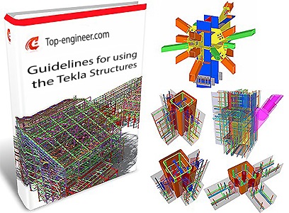
Guidelines for using the Tekla Structures
Introduction
1.1 Who can benefit from studying present guidelines
1.2 Tekla Structures features map and application fields
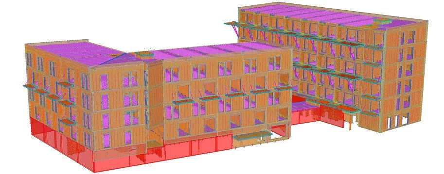
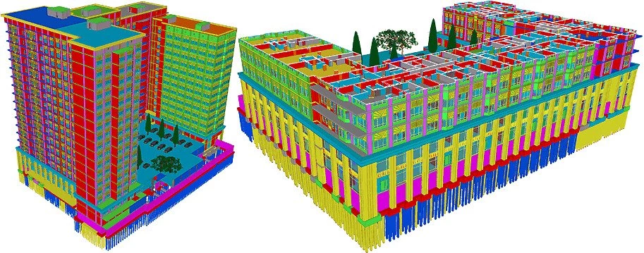
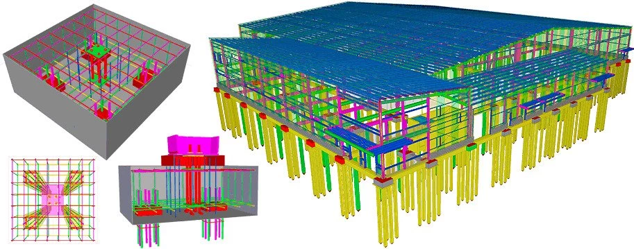
1.3 Field cases executed in Tekla Structures
1.4 PC System requirements for using the Tekla Structures
1.6 Tekla Structures installation tips
1.5 Where to download the Tekla Structures training version
1.7 Tekla Structures localization packages
1.8 Launching Tekla Structures
First step *
2.1.1 Creating a new project
2.1.2 The main menu elements in Tekla Structures
2.1.3 Minimizing/ maximizing the model in Tekla Structures
2.1.4 Rotating a model in Tekla Structures
2.1.5 Creating standard views in the model by XY, XZ, ZY axes in Tekla Structures
2.1.6 Arranging/switching views in Tekla Structures
2.1.7 Switching to the view plane in Tekla Structures
2.1.8 Dragging the view plane in Tekla Structures
The “Grid” tool
2.2 The “Grid” tool in Tekla Structures
2.2.2 The “Modify” button of the Tekla Structures “Grid properties”
2.2.3 Creating a complementary grid in Tekla Structures
2.2.4 Saving the current grid settings in Tekla Structures
2.2.5 Uploading the saved grids configurations into other Tekla Structures models
2.2.6 Setting out the snapping tools
2.2.8 Copying a grid in Tekla Structures
2.2.7 Moving grids in Tekla Structures
2.2.9 The “Radial grid” tool in Tekla Structures
Steel columns
2.3 Steel columns in Tekla Structures
2.3.1 Creating columns in Tekla Structures
2.3.2 The “Column Properties” menu in Tekla Structures
2.3.3 The “Cancel” and “Close” buttons in Tekla Structures
2.3.4 The “Apply” button in Tekla Structures
2.3.5 The “Ok” button and its main distinctions from the “Cancel”
2.3.6 The “Get” button in Tekla Structures
2.3.7 The “Modify” button in Tekla Structures
2.3.8 The position of a column in Tekla Structures
2.3.9 The “Deforming” tool of the “Column Properties”
2.3.10 Simultaneously setting up particular attributes in Tekla Structures
2.3.11 The “Save settings” box in Tekla Structures
2.3.12 The “User-defined attributes” of the “Column
2.3.13 The “Mini toolbar” in Tekla Structures
Snapping tools/ Selecting tools/
2.4 Snapping tools/ Selecting tools/ Object types in Tekla Structures
2.4.1 Selecting and ignoring objects by type
2.4.2 Snapping an object to the geometry
2.4.3 Snapping to the object reference/corner points
2.4.4 Selecting objects by frame in the left-to-right and right-to-left direction
The Construction geometry
2.5 The “Construction geometry” tools in Tekla Structures
2.5.1 The “Points” tool in Tekla Structures
2.5.2 The “Construction line” tool in Tekla Structures
2.5.3 The "Orthogonal regime" in Tekla Structures
2.5.4 The "Construction circle" tool in Tekla Structures
2.5.5 Dividing a construction line into a specified number of segments
2.5.6 The “Construction plane” tool in Tekla Structures
2.5.7 Other construction geometry tools in Tekla Structures
The Contour plate
2.6 The “Contour plate” tool in Tekla Structures
2.6.1 Create contour plate in Tekla Structures
2.6.2 The “Contour plate Properties” menu in Tekla Structures
2.6.3 Selecting a point from the contour plate surface in Tekla Structures
2.6.4 Chamfers of a contour plate object in Tekla Structures
2.6.5 Selecting a group of points at a contour plate in Tekla Structures
2.6.6 Moving a group of points in Tekla Structures
2.6.7 Adding and deleting points at/from the contour plate in Tekla Structures
2.6.8 Creating a base plate
2.6.9 The “Cylindrical bend plate” tool in Tekla Structures
2.6.10 The “Conical bent plate”tool in Tekla Structures
2.6.11 The “Stand-alone bent plate” tool in Tekla Structures
2.6.12 The “Lofted plate” tool in Tekla Structures
The Steel Beam tool
2.7 The “Steel Beam” tool in Tekla Structures
2.7.1 Creating beams in Tekla Structures
2.7.2 Distinctions between a column and a beam in Tekla Structures
2.7.3 Transforming a beam into a column and vice versa
2.7.4 The “Polybeam” tool in Tekla Structures
2.7.5 Curved beam in Tekla Structures
2.7.6 The “Twin profile” tool in Tekla Structures
2.7.7 The “Split” and “Combine” tools in Tekla Structures
2.7.8 The “Orthogonal beam” tool in Tekla Structures
2.7.9 The “Spiral beam” tool in Tekla Structures
2.7.10 The “Item” tool /IFC in Tekla Structures
Moving objects
2.8 Moving objects in Tekla Structures
2.8.1 Moving objects using the Ctrl+M hotkey combination
2.8.2 The “Move Linear” tool in Tekla Structures
2.8.3 The “Move Special - Rotate” tool in Tekla Structures
2.8.4 The “Move Special - Mirror” tool in Tekla Structures
2.8.5 The “Move Special- To another plane” tool in Tekla Structures
2.8.6 The “Move Special - To another object” tool in Tekla Structures
The Copy tool
2.9 The “Copy” tool in Tekla Structures
2.9.1 The “Copy” tool by using the Ctrl+C hotkey combination in Tekla Structures
2.9.2 The “Copy Special - Linear” tool in Tekla Structures
2.9.3 The “Copy Special - Rotate” tool in Tekla Structures
2.9.4 The “Copy Special-Mirror” tool in Tekla Structures
2.9.5 The “Copy Special - to another plane” tool in Tekla Structures
2.9.6 The “Copy Special - To another object” tool in Tekla Structures
2.9.7 The “Phase manager” tool in Tekla Structures
2.9.8 The “Copy from another model” tool in Tekla Structures
The added material tools
2.10 The added material tools in Tekla Structures
2.10.1 The “Cut part with line” tool in Tekla Structures
2.10.2 The “Fit part end” tool in Tekla Structures
2.10.3 The “Cut object with polygon” tool in Tekla Structures
2.10.4 The “Cut object with part” tool in Tekla Structures
The Chamfer tool
2.11 The “Chamfer” tool
2.11.1 The “Create chamfer - For part edge” in Tekla Structures
2.11.2 The “Create Chamfer - For part corner” tool in Tekla Structures
The Bolts tool
2.12 The “Bolts” tool in Tekla Structures
2.12.1 The bolted joints in Tekla Structures
The Measure tools
2.13 The “Measure” tools in Tekla Structures
2.13.1 The “Measure - Vertical distance” tool in Tekla Structures
2.13.2 The “Measure - Horizontal distance” tool in Tekla Structures
2.13.3 The “Measure - Distance” tool in Tekla Structures
2.13.4 The “Measure - Bolt spacing” tool in Tekla Structures
2.13.5 The “Measure -Angle” tool in Tekla Structures
2.13.6 The “Measure -Arc” tool in Tekla Structures
The Surface treatment
2.14 The “Surface treatment” tool in Tekla Structures
2.14.1 The “Surfaces” tool in Tekla Structures
2.14.2 The “ Surface treatment to part face” tool in Tekla Structures
2.14.3 The “ Surface treatment to all faces of part” tool in Tekla Structures
Views
2.15 Views in Tekla Structures
2.15.1 The “Basic View” in Tekla Structures
2.15.2 Selecting views in Tekla Structures
2.15.3 The “View depth Up/ Down” field
2.15.4 The workplane in Tekla Structures
2.15.5 Saving views / The View list in Tekla Structures
2.15.6 Creating views in Tekla Structures
2.15.7 The “Hide” tool
2.15.8 The “Show only selected” tool
2.15.9 The “Show with exact lines” tool
2.15.10 The "View properties" window / The "Display" button
2.15.11 The “View Settings” menu / “Display” button/
The Weld tool
2.16 The “Weld” tool in Tekla Structures
2.16.1 The “Create weld between parts” tool in Tekla Structures
2.16.2 The main component of an assembly in the Tekla Structures
2.16.3 The “Create polygon weld” tool in Tekla Structures
2.16.4 The “Convert to polygon weld” tool in Tekla Structures
2.16.5 The “Create weld to part” tool in Tekla Structures
2.16.6 The “Prepare part for welding with another part” tool inTekla Structures
2.16.7 The “Prepare part for welding with another part” tool in Tekla Structures
2.16.8 The Welding assignment
Non-Uniform beams
2.17 Non-Uniform beams in Tekla Structures
2.17.1 Non-uniform beams created of a profile in the Tekla Structures
2.17.2 Welded uniform cross-section beams in Tekla Structures
2.17.3 Welded non-uniform cross-section beams in Tekla Structures
2.17.4 The SIN beams in Tekla Structures
Concrete pour
2.18 The “Concrete pour” modeling tools in Tekla Structures
2.18.1 The “Concrete column” tool in Tekla Structures
2.18.2 The “Add to/Remove from cast unit” tool in Tekla Structures
2.18.3 The “Concrete beam” tool in Tekla Structures
2.18.4 The “Strip footing” tool in Tekla Structures
2.18.5 The “Concrete panel” tool in Tekla Structures
2.18.6 The “Concrete polybeam” tool in Tekla Structures
2.18.7 The “Concrete slab” tool in Tekla Structures
2.18.8 “Add to/Remove from part” tool in Tekla Structures
2.18.9 The “Spiral beam” tool in the Tekla Structures
2.18.10 The “Lofted plate” tool in Tekla Structures
2.18.11 The “Floor layout” tool in Tekla Structures
2.18.12 The “Wall layout” tool in Tekla Structures
2.18.14 The “Pour view” and “Pour break” tools in Tekla Structures
Rebar modeling
2.19 Rebar modeling in Tekla Structures
2.19.1 The “Single bar” tool in Tekla Structures
2.19.2 The “Bar group” tool in Tekla Structures
2.19.3 The “Rebar shape catalog” tool in Tekla Structures
2.19.4 The “Create rebars by point input” tool
2.19.5 The “Group”/ “Ungroup” tools in Tekla Structures
2.19.6 The “Rebar Splice” tool in
2.19.7 Rebar sets in Tekla Structures
2.19.8 The reinforcement mesh in Tekla Structures
2.19.9 Prestressed reinforcement in Tekla Structures
This Book is Available for Purchase
If you liked this book, you can purchase full access to its content.
Buy Full Access