The "Concrete pour" modeling tools are put together into a separate tab located on the main menu bar. Let’s subsequently study all the tools, though to a significant extent they are similar to the steel modeling instruments.
The "Concrete column" tool is similar to the "Steel column" tool. Let’s create a concrete column by enabling the respective tool at the main menu bar and pointing out its location at the view.
Create a steel column next to it and simultaneously open the objects'
As you can see, the objects' "Properties" windows are defined
The only difference between these objects stands for "Numbering" field parameters. In the older TS interface, numbering parameters are even placed under a separate tab.
Let’s make sure that all the other parameters are similar. Go to
Let’s investigate the “Deforming” section.
The only difference between these column types is that the concrete column is not available at numbering series parameters, such as "Part numbering" and "Assembly numbering", as concrete parts can not be welded on into an assembly.
Superseding the material type from steel to concrete, and vice versa.
One of the most important characteristics of all steel and concrete modeling tools is that they are interchangeable. Thus switching the material type of a steel column to any available from the concrete material catalog automatically changes the object’s properties as it was initially created using the “Concrete column” tool. Similarly, the converse is also true.
Repeatedly open the "Column Properties" menu. As you can see, the "Properties" window from now on is defined by the concrete column object type. The column's I-beam shape remained unchanged, though it is exactly the concrete column. See below:
Go to the “Cast unit” section. Note that the "Cast unit numbering prefix" was transferred from the "Assembly prefix", but the "Part numbering" field has disappeared at all.
The "Cast unit" field defines the parameter which is characteristic only for concrete objects. It is necessary for providing compatibility between various license types. New license types are no longer containing this parameter, though Tekla Structures is still available on such a field. We will examine in detail this parameter functionality when getting to the SST drawings chapter.
Toggling between the cast unit values does not affect the model in any
The profiles of concrete elements are completely different from the respective profiles of the steel elements. When modeling steel structures it is not recommended to use parametric profiles as they do not contain ISO specifications, according to which objects should be manufactured. Concrete elements are not bought-out components, thus it is recommended to use parametric profiles while modeling concrete objects. The rectangular sectioned profiles are of frequent use. Let’s try out writing into the profile field value of “ 600*400 ”.
The round cross-section columns are defined by the profile names which
The full list of parametric profiles is available at the "Profile
Select profile No. “PRMD500*300-250*150”, which allows creating
Similar to the previous tool, the "Concrete lofted plate" tool's functionality is analogous to the "Steel lofted plate" tool, which we have already examined. Thus we will not investigate the properties of this tool in detail.
For any reference about how to use this tool, please address the "Instructor" tab at the TS right side vertical menu bar. At the "Instructor" window, you can find all necessary information for operating the “Lofted plate” tool.
Enable the “Lofted plate” tool, and once done, in the "Instructor"
Try out operating the "Instructor" window by yourself. When activating any other tool, the contents of the window are automatically switched.
This tool draws up lift slab series of a definite interval, clearance, and reinforcement settings. Basically, it is a separate application that allows drawing up complex structures.
Create a lift slab with dimensions of 1200 x 6000 mm.
The algorithm for using the “Floor layout” tool:
It is important to mention that the present tool does not create any new object type, thus a double-click on it does not bring up the "Properties" window. This tool is just an internal TS app that is drawing up lift slabs. Execute a double-click at the object and get the “Floor layout” window open.
As you can see, this tool (component) is not defined by a large settings
Let’s add up a new slab layer by activating the respective Icon, selecting the required object, and confirming the action by pressing the “Modify” button. Refer to the below:
We will examine this tool at the following practical assignment, where
The present tool is not a fully functional and stand-alone instrument. It is just a plugin located at the software's main interface, allowing creating multilayer walls simultaneously for numerous model sites.
The algorithm for using the "Wall layout" tool is as follows:
As the result, you can see the wall objects, which are split into numerous
Note, that by applying this instrument, you can model unit panels as well as cast in place walls. When modeling monolithic walls, do not unite into a single cast unit all the floor elements, this being an error. Only straight sections can be united into a cast unit.
Also, do not consider the junctures, as in the TS junctures are
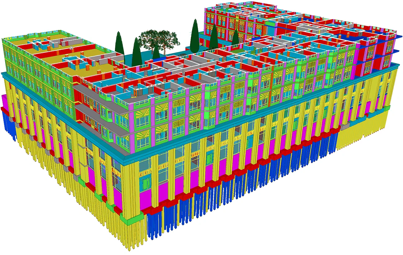
Thus in the above picture, you can see that every structural element is modeled as a distinct component, though in reality, the whole structure is cast in place.
Note that software creates on its own several components, thus splitting the complex layout of the walls into simple segments. Go to the object's "Properties" menu by double-clicking on it. Add one more layer by enabling the respective menu button.
To apply the updated parameter's values to all the objects, press the "Modify" button. If no objects are selected, the "Modify" button does not work.
Exercise to randomly configure the wall properties on your own.
We will investigate in detail the “Wall layout” plugin functionality
The cast-in-place structures are usually split into definite segments (breaks). It is a conventional splitting, which is visible in the drawings. See below the tools' allocation at the main menu bar.
To investigate the toll's functionality, create a concrete column
Set out the cast unit type as "Cast in place". Not switching to the "Cast in place" type does not allow applying the pour breaks to the model.
The reason is that precast units do not require breaks. Do not miss out
Enable the first tool for creating a pour break by a single point.
The algorithm for applying the "Pour break"/ "Single point"
In the drawing, the pour break is defined as a line with ticks.
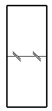
Go to the "Pour break Properties" menu. There are available only two textual fields defining various characteristics and notes to the pour break.
You may fill in these fields with the necessary information to be reflected
Switch off the "Direct modification" tool. Select the pour break and move it into the upward direction at 250 mm by using the Ctrl+M hotkey combination.
Thus you can see that the pour break plane is available for moving by
Switch on the "Direct modification" tool.
Select the pour break. Further, select one of its points and drag it downwards
As you can see from the above, the pour break plane is no longer perpendicular to the column body and is defined by a tilting angle with reference to it.
Select an intermediate imaginary point and drag it downwards in the way
|
Thus we can conclude that pour breaks can be of various shapes, which are reflected in the drawings.
The current pour break shape is similar to the below:
|
The “Pour break”/ “Two points” tool
Create a column with a profile of 400*400 and a 1000 mm height. Do not miss out on specifying the concrete unit type as "Cast in place".
The algorithm for using the "Pour break"/"Two points"
The “Pour break”/ “Multiple points” tool allows creating a pour break at a definite tilt angle by a broken line.
Create a column with a profile of 400*400 and a 1000 mm height. Do not miss out on specifying the concrete unit type as "Cast in place".
The algorithm for using the "Pour break"/"Multiple points"
The “Pour view” tool allows selecting each pour break apart, missing out on selecting the concrete object itself.
Create a beam of 1000 mm height. Do not miss out on specifying the concrete
Create several pour breaks by using the “Pour break”/”Single
Enable the "Pour view" tool. Clicking on the tool's button
In the "Pour view" regime, it is possible to select pour breaks
Let's copy the selected pour break. Enabling the Ctrl+C hotkey combination alerts the user that the operation is not possible in the current regime. Thus switch off the "Pour view" tool.
Confirm the rendering regime update by pressing the "Display"
Now, you can select the whole object. Select it and proceed to copy
Change the class value of the initial part to assure a better visual representation:
Enable the “Pour view” tool.
Try out selecting the pour breaks. Although there are two distinct concrete
Select all the pour breaks and go to the right-click menu and enable the
Tile the views vertically. Note that the "Pour view" tool works
Thus you can enable the tool at the required view.
Enable the "Pour view" tool for the new "(Basic view)"
Select the initial view and disable the “Pour view” tool for
You can simultaneously select in the views various parts of the same object with the "Pour view" settings individually adjusted for each view.
Try out the above using the Ctrl key and referring to the below:
Note that selecting one and the same area at various views brings out different results according to the current "Pour view" settings of the view.
Now create one more copy of the initial object at the distance of two
The TS may inquire about expanding the view.

Press the “Do not Expand” button as the copied object will
Change the copied object class value at 6.
Note that the new object has no pour breaks. The reason for this is that
Create one more copy of the object placing it in the gap between already
Upon completion of the copying operation, the pour breaks automatically
Change the class value for the new object at 7 to assure a better visual representation. Thus we can conclude that each pour break is a limitless plane that creates cuts in all adjacent concrete objects.
Select all concrete objects and copy them to the right where no pour breaks
Thus you can see, that a pour break is a three dimensional plane automatically
With the "Pour view" tool switched on, you can see that the right-side object elements united into one object, ignoring the pour breaks of the initial elements.
Exercise on your own to use the "Pour break" tool to get a better
Let’s create a foundation by using the "Concrete column"
Enable the tool and create an arbitrary column.
Set up the column properties according to those presented in the below
|
Profile |
Class |
Top position |
Bottom position |
|
1600*1600 |
10 |
-1500 |
-2200 |
Create one more arbitrary column at the same point as the previous one.
Configure the column according to the below:
|
Profile |
Class |
Top position |
Bottom position |
|
800*800 |
10 |
-250 |
-1500 |
Let’s create a third column as well.
Configure the column according to the presented below:
|
Profile |
Class |
Top position |
Bottom position |
|
PRMD800*800-700*700 |
13 |
-150 |
-250 |
Let’s check out the resulting object in 3D.
It is important to have a clear understanding that separate foundations can be of various shapes, dimensions, and materials, depending on the multiple site factors such as loads, soil types, etc. The present example is not the only possible separate foundation configuration.
To assure a separate foundation correct shape, before mantling the surface preparation is performed. Thus concrete is poured not directly into the sand but onto a concrete setting bed. Let’s create a setting bed by using the concrete column tool. Preset the tool, according to the below:
|
Profile |
Class |
Top position |
Bottom position |
|
1700*1700 |
6 |
-2200 |
-2300 |
Compare your results to the below:
Let’s analyze the assembly sequence: pouring up the setting bed at the levels from -2300 to -2200 and forming a hard surface for the foundation, where the setting bed material differs from the foundation material, pouring up at a time the foundation body from -2200 to -250 mm, this being represented in the current model by 2 elements marked in green, which shall be united into a cast unit.
The algorithm for adding elements to a cast unit is as follows:
Note that visually nothing has changed, although now elements are united
To make sure the elements are united, left-click at any of them by holding on the "Alt" button pressed, thus the whole cast unit element is selected.
Also, the "Create cast unit" tool is available at the main menu bar, however depending on the localization package settings it can be hidden, but available for display.
See below the algorithm for editing the ribbon.
The “Create a cast unit” tool.
To understand the main functionality principles of the “Add to/Remove from cast unit “ tools, let’s, first of all, add one more element to the cast unit which we have already created. Enable the appropriate tool:
The main component of a cast unit is highlighted with pink color. Exactly the components prefix defines the respective of the cast unit. The other element’s prefixes are ignored analogously to the previous assemblies examined.
Switch on the “Select assemblies” tool and try out selecting
Enable the “Select objects in assemblies” tool and try out
Although the same objects are selected, the above are not equivalent methods of selecting cast units. Let’s conventionally agree upon using the Alt-key method as a preferable one.
To inquire about the cast unit main component it is sufficient to
The “Remove from cast unit” tool.
A cast unit may include many components, thus a user may be required to delete any of the objects. Thus the “Remove from cast unit” tool becomes necessary.
Let's try out deleting a component according to the below algorithm
Now, when selecting the cast unit simultaneously holding the "Alt"
The “Add to cast unit” tool.
This tool works opposite to the previous one, as it allows adding an element to an already existing cast unit. Also, this tool switches the main component of the unit by substituting the selecting sequence.
Let’s add up an element to the cast unit.
Note that TS does not require reappointing all the cast unit parts, but
Repeat the above:
Now all the parts are included in the cast unit. Check on this by clicking
The “Explode” tool.
This tool ungroups the objects belonging to a cast unit.
The algorithm for using this tool is as follows:
Now each element is selected separately, even if you hold on the "Alt"
Now we have examined all the “Cast unit” menu tools.
Let's unite all green parts into an assembly, as in practice, it is
Go to the view plane by enabling the Ctrl+P hotkey combination. Select the separate foundation object created, and allocate it under a column center of the test steel structure created.
Check the correctness of the executed operation. Copy the separate foundation
Compare our results to those presented below:
The “Concrete footing” tool is practically identical to the “Concrete column”, except for the fact there are no "Deforming" parameters applicable to it.
It is only possible to set out various profile types with no shape modifications to be configured. As there are no other differences between footings and column tool parameters list, we will not focus on considering them repeatedly.
The “Concrete beam” tool creates a horizontal section of a definite profile. It differs from a column only by the fact that a column can be built up strictly vertically, but a beam at any position. Tilting a column automatically transforms it into a beam and vice versa.
In fact, this tool is applicable for drawing up practically every kind
Delete all the beams in the model at the elevation point of +0,000.
Rotate the view in the way to concomitantly select all the beams at a
Select the beams by framing them and press the "Delete" button.
Open the available views menu by enabling the Ctrl+I hotkey combination.
As you can see, there is no elevation level of -0,250 mm. Let’s
Go to the -0,250 elevation view.
Rotate the view and set up the "View depth" at its "Up"
Create a concrete beam with the profile 800*300 and a class equal to 6
Compare your results to the below:
Copy the beam in the way to connect all the columns as it is shown below:
At the curved base portion analogously connect the columns by beams preventively setting out the curved beam radius at 12000 mm, and the number of segments equal to 50.
Similar to the steel beams, the concrete beams are adjustable by the “Polygon cut”, “Line cut”, “Fit part end” tools. Let’s apply the “Fit part end” to the beams, to test out how it works with the concrete objects.
Fit all the necessary beams.
Further, by using the "Copy Special/ Mirror" tool, create all
Compare your results to those presented below:
Conclusions:
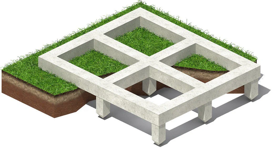
The “Strip footing” tool is similar to the “Steel Polybeam” tool. Substantially it is just a beam drawn up by a broken line defined by several points.
The similarity of the concrete modeling tools with the steel modeling tools is a quite logical one, though there are three almost identical instruments, such as “Strip footing”, “Concrete panel”, “ Concrete polybeam”.
The “Strip footing” tool is of rare use as all the concrete elements are preferable to be created by straight lines using the “Create beam by two points” tool. The “Strip footing” tool functional is not reflected by its title, as it can be used for modeling any concrete volume, with no account for the object type: foundation, panel, girt, or any other.
This tool is practically identical to the “Strip footing” tool. It is brought out to a separate tab to assure a fast setting switching, where one tool creates a definite beam type, second - another beam type, and so on.
Naturally, you can use the “Footing” tool for creating a panel,
It is a very confusing situation for inexperienced users. Let’s
This is the third tool that we will try to avoid using when modeling structures.
As all the above tools work similarly, then let’s examine them concomitantly.
Applying these tools shall be reasonable as any geometry has to be as simple as possible. Let’s create a rounded beam by using the “Polybeam” tool.
In fact, the geometry created is similar to the previously established one, just we have used another methodology. As we have not specified the number of segments, thus their quantity is infinite.
The most frequent mistake of inexperienced users is modeling , for example, walls of a room by a single closed beam. It is compulsory to avoid creating corners and necessary to draw up simple straight-lined beams, thus cast unit drawings will get correct.
The “Concrete slab” tool is completely similar to the “Steel plate” tool. Employing this tool it is possible to model any concrete volumes, slabs, and wall panels. If the “Concrete beam” tool allows creating a segment of a defined profile, then the “Concrete slab” tool establishes a polygon shape object of a definite thickness.
Let’s create a polygon with dimensions of 1000*2000*200 and the
Note that at the "Concrete Slab Properties" menu the “Position”
Let’s create a foundation slab in the current model. For this proceed
Configure the "View depth"/"Up" field value at 0 for
According to the below scheme, unite the extreme points of the model.
Compare your results to the below:
Likewise, proceed to the extreme right point of the foundation slab. Here we might face the situation when rounding does not work out. This is one of the Tekla Structures specific features which does not allow rounding more than one point of a slab with dimensions over 2000 mm. Let’s investigate the case, though it is not the one frequently occurring, as such sizable objects usually are not due to rounding.
Let’s examine the bug, by creating two squares with dimensions:
Select all the eight points of the squares, and configure the "Chamfer type" to “Arc point”.
As we can see the 2000 mm face square could not get rounded correctly at all the points. However, in the current model, we have to create rounding bilaterally, but the slab polygon dimensions are over 2000 mm.
Let’s create a different concrete polygon, basing on another scheme
Compare your results to those below:
Let’s create one more polygon. refer to the below picture:
Select the polygon and at one of its points set out the chamfer value
Further, by using the “Copy Special/ Mirror” tab, copy the
Thus we created the foundation geometry. Now we have to unite all the
We have already examined the “Add to assembly” tool. The following instrument to be investigated is the “Add to part” tool. Note that the “Add to assembly” and “Add to part” tools are quite similar, though still carry out different functions. Let’s find these tools at the main menu bar, see below:
|
Before commencing work using the “Add to part” tool, let’s clear up the difference between a part and an assembly exemplified by Lego kits. All the structures are composed of prefabricated parts. These prefabricated parts are mantled into assemblies (into a small homunculus), which is a definite entity, specified by unique drawings and numbering. The single part drawings are principally different from the assembly drawings. SST drawings are separately defined by single part drawings and assembly drawings when the RC drawings are described only by the cast units drawings, as there are no special requirements for concrete parts drawings.
|
|
The part represents the smallest undividable units of a structure, which in total form an assembly (cast unit, homunculus), at the same time all the parts might be of various characteristics. All the similar parts are automatically numbered by the TS, but different parts automatically get unique numbers. For steel parts, it is possible to generate automatic drawings.
|
|
An assembly represents a group of united parts. Assemblies are defined by unique numbers, distinct from the single parts numbering. Thus creating exactly the same homunculus of various postures, makes the TS consider each shape as a separate assembly and respectively assign to each assembly a unique number. If the parts of an assembly are absolutely identical and their layout is similar, then TS will assign to such assemblies the same numbering title. Also, it is possible to automatically create all the assembly drawings, as the TS knows the quantity of all unique assemblies in the model and indicates this number in the drawings.
|
Let’s proceed to unite the foundation parts in the way to form out
The algorithm for using the “Add to part” tool:
Select the view by clicking on it and apply the “Redraw view” tool. Thus you can see that the seam between the parts disappeared, as the part turned to be an integral one.
Let's unite 2 more parts. See below:
Let's unite 2 more parts. See below:
Redraw the view.
Thus we have created an integral part consisting of several parts. It is important to mention that an integral part object is defined by a single (common) profile, class type, and other attributes, as well as there are no seams between the parts.
Now, let’s delete from the integral part one of the parts.
Therefore go to the "View settings" and enable the “Cuts and added material” checkmark, as exploding the part requires indicating its components.
Further, let’s exclude a part from the integral one.
The algorithm for using the “Delete from part” tool is as
Now select the updated integral part, and make sure that one of its components
If it is required to completely divide an integral part into components,
The algorithm for using the “Explode part” tool:
Thus the integral part was divided. Apply to each part a different
Thuswise users can create complex integral parts by uniting simple ones and create assemblies (cast units) at the same time controlling the element's line position.
To avoid any confusion between “Add to part” and “Add to assembly” tools, note that adding to part is reasonable when the seam between parts is unacceptable and the parts are defined by the same material type. In all other cases use creating cast units or assemblies.
The “Concrete spiral beam” tool is similar to the “Steel
The algorithm for using the “Spiral beam” tool:
Go to the “Spiral beam properties” menu by executing a double-click
Edit the rotation angle value to 270 degrees.
Rotate the view in 3D to see that the spiral beam is plain.
Write into the “Total rise” field the value of 8000 mm.
If required, it is possible to twist the spiral beam body around its axis.
In order to get that done, set up the “twist angle at start”
By using the “Spiral beam” tool it is possible to create objects
of a complex shape, such as circular stairs and etc.
