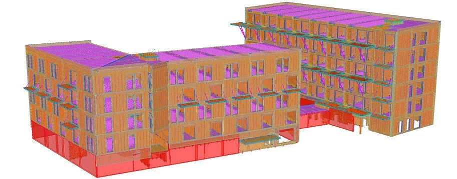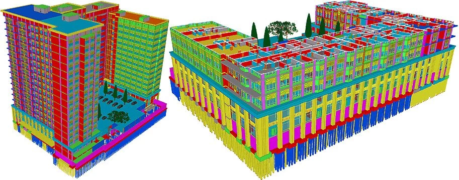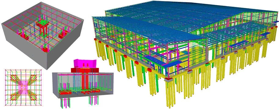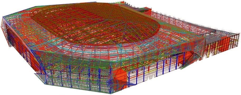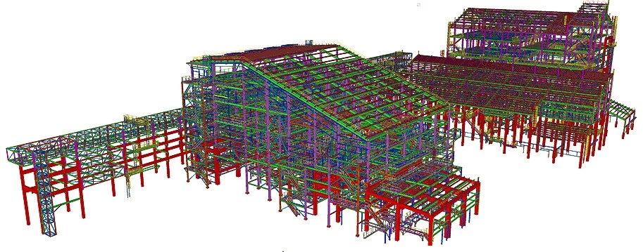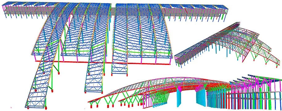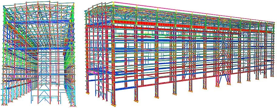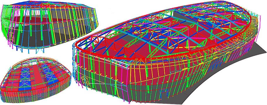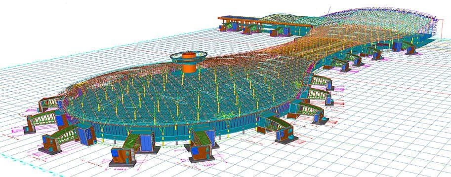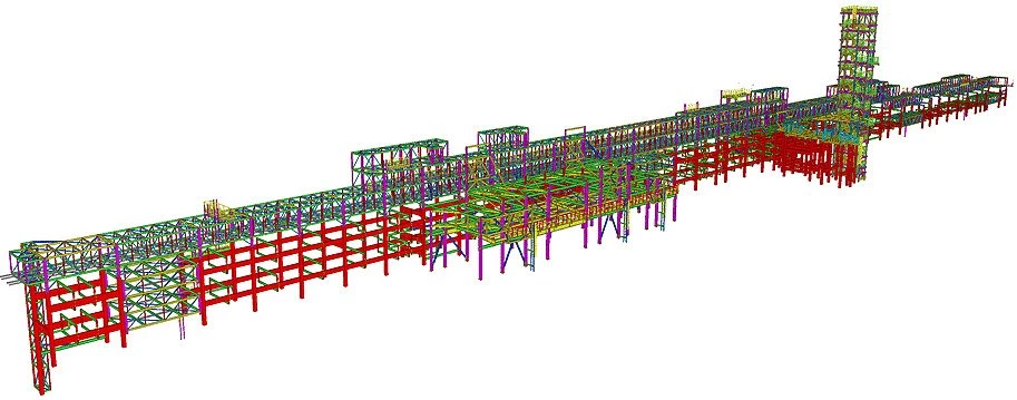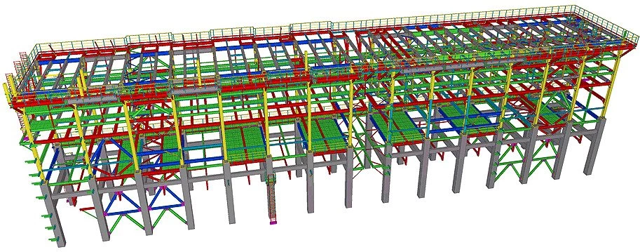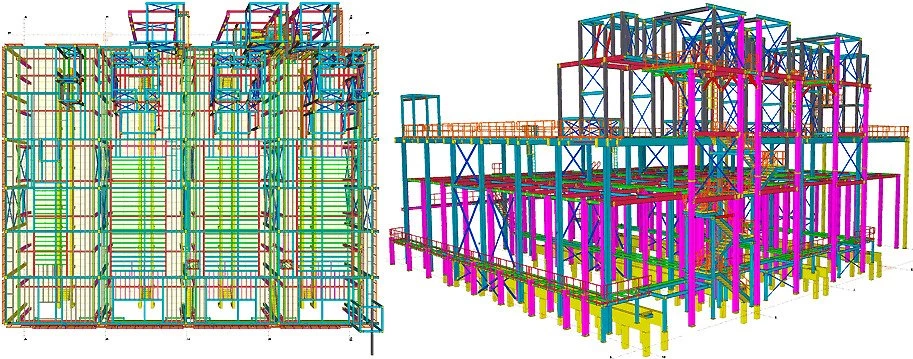
In TS a column is defined as any vertically aligned segment. The “Column” tool can be found on both tab pages “Steel” and “Concrete”, having different sets of characteristics. Thus steel and concrete drawings are different.
Note that a beam drawn up vertically is automatically converted to a column in Tekla Structures. In the advanced settings menu, it is possible to set up the inclination angle value defining a beam conversion to a column.
Any segment built up in 3-dimensional space is enclosed between two points. The “Create column” tool allows drawing up a segment by indicating just one point. The information about the segment's top and bottom points is specified in the “Column properties” menu defining their exact coordinates in the model.
First of all, let’s find all the “Steel” and “Concrete”
modeling tools on the TS main toolbar.
Let’s draw up a steel column located at an arbitrary intersection
Note: all the new columns created are defined by the values of the parameters
Sometimes, it is of no relevance to simultaneously reflect all the parameters in the "Properties" menu. Usually, there is a need to define only some particular parameters, without paying attention to the others.
Let’s get back for a while to the “Modify” button functioning, which is to apply changes to the selected objects of the model, according to the values of the parameters specified in the respective fields. Each field of the "Properties" menu is accompanied by a check-box, which enables or disables the parameter effect in the model.
In the old Tekla Structures versions, all the "Properties" fields are constantly displayed regardless of the fact if the parameter value is modified. If the check box next to the properties field is active, then the “Modify” button considers the current value of the parameter when running its function; if the checkbox is not active, then the value of the parameter is not taken into consideration.
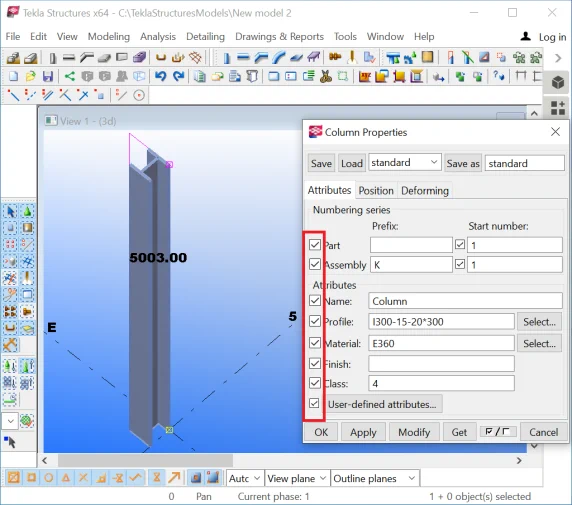
Unless the value of a parameter is changed, the check-box next to it is not active. As soon as an attribute's value gets modified, its check-box gets activated. Thereafter, pressing the “Modify” button executes changing the object, considering the updated values of the parameters with active check-boxes.
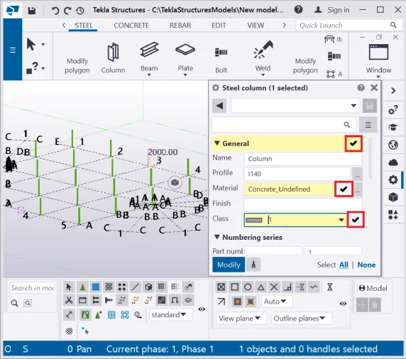
Switching off a check-box referent to a parameter field results in neglecting the parameter value when pressing the “Modify” button.
Simultaneously properties modification for several objects .
Simultaneous properties modification of an objects’ group starts with selecting the respective objects in the model. However, a bulk selection of any other unsolicited object’s type may accidentally occur. Then the “Modify” button proceeds on the properties modifications only for the type of objects, whose "Properties" menu is active. Thus other selected object types are ignored.
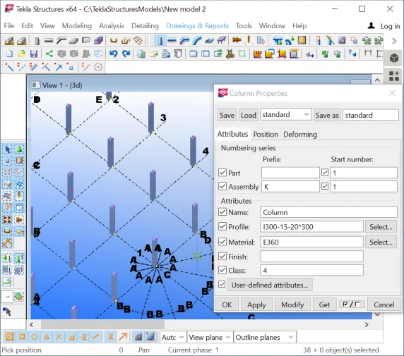
Let’s exercise the above by first of all creating various strings
|
|
String by axis 1 |
String by axis 2 |
String by axis 3 |
String by axis 4 |
String by axis 5 |
|
Top position |
0 |
6000 |
6000 |
12000 |
12000 |
|
Bottom position |
-6000 |
-6000 |
0 |
0 |
6000 |
|
Class/color |
1 |
2 |
3 |
4 |
5 |
|
Cambering |
0 |
0 |
0 |
2000 |
2000 |
To ease the process of selecting the required objects, rotate the view in the convenient way, displaying the column string you are working at. Use the specifications mentioned in the above Table when creating the column strings.
Proceed in the same way for the other strings of columns.
Select all the columns and modify the "Bottom Level" value to -6000. Setting up the bottom level value automatically modified the values of the restant parameters as well, this being a logical consequence.
In the older Tekla Structures versions, the simultaneous properties modification of the group of objects is done by default, and requires selecting the objects and pressing the “Modify” button.
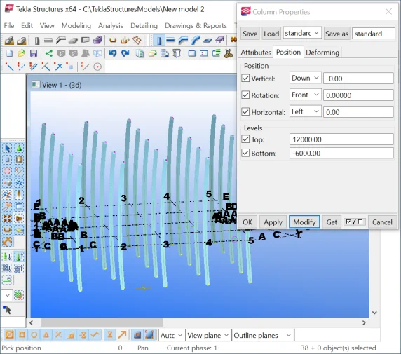
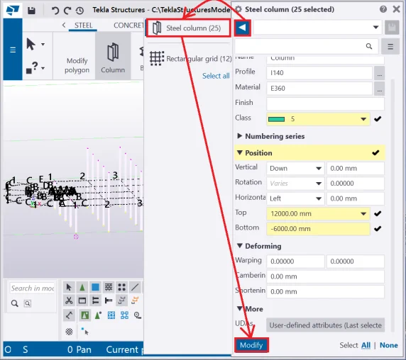
The algorithm for simultaneous properties modification of a group of objects in the new TS versions is as follows: select an object, execute a double-click on it, go to the "Object Properties" menu, press on the "Brush" button, and frame the required-to-change objects. If other object types are accidentally gripped, then indicate the required type of objects in the "Properties" menu by activating the respective checkboxes and press the “Modify” button. If there are active parameters fields with missing values, the TS will highlight them by a red frame, thus facilitating finding them out of the list.
Restore the model configurations by pressing the CTRL+Z hotkey combination.
Let’s proceed with setting up and applying values of particular parameters, namely editing only the “Column level”/ “Bottom” value.
In the older TS versions, to modify an object by setting up values to some particular parameters, it is necessary to deactivate all the check-boxes of the "Properties" menu and mark up only the ones required. Filling in a value into an inactive property field, automatically enables the referent check-box.
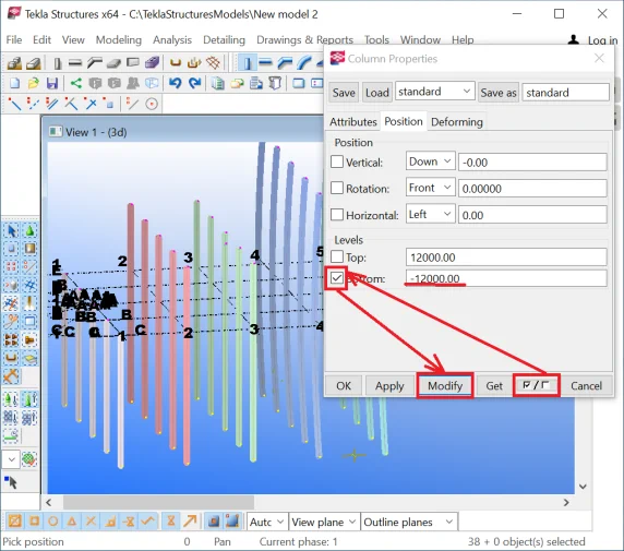
In the new TS versions, to modify an object by setting up values to some particular parameters, it is necessary to select the object, to disable all the checkboxes by addressing the "Brush" button, to specify the updated value in the respective field (in the current case study: the bottom level) and to press the “Modify” button.
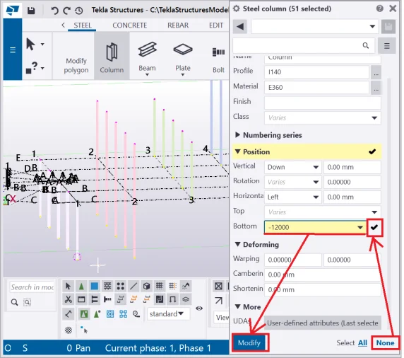
Exercise the above and modify the “Material” field values
Upon completion, delete all the columns from the model.
Saving settings is a very convenient tool for drawing up a massive number
Thus SSD target specification is composed of various tables containing information about the profile types, assemblies prefixes, materials, etc.
Let’s set up the parameters indicated below and save up the string
|
|
Attribute |
String by axis 1 |
String by axis 2 |
String by axis 3 |
String by axis 4 |
String by axis 5 |
|
1 |
Name |
Column |
Column |
Column |
Column |
Column |
|
2 |
Assembly numbering/ Prefix |
HEA1 |
HEA2 |
HEA3 |
HEA4 |
HEA5 |
|
3 |
Profile |
HEA180 |
HEA400 |
HEA500 |
HEA900 |
HEA1000 |
|
4 |
Material |
E360 |
E295 |
E360 |
E335 |
S420 |
|
5 |
Position/ Top |
6000 |
6000 |
10000 |
10000 |
10000 |
|
6 |
Position/ Bottom |
-250 |
-250 |
-250 |
-250 |
-250 |
|
7 |
Class/ color |
1 |
2 |
3 |
4 |
5 |
|
8 |
Cambering |
0 |
0 |
0 |
2000 |
2000 |
As an example, let’s examine the first column of the above table.
Fill in the data into the properties menu fields, set up the name of the
configuration to be identical to the assembly prefix value (the title of
the configuration may be of any arbitrary value) and save the configuration
by pressing the “Save as” button at the top side of the "Properties"
menu.
Repeat the above algorithm for each column of the table, by saving every
new set of properties under the correspondent assembly prefix value. Open
the saved set of properties list and double-check if all the configurations
are saved.
Create columns according to the tabular data to be aligned at the axes 1 -5. The below algorithm will be a solid reference for you for executing this task:
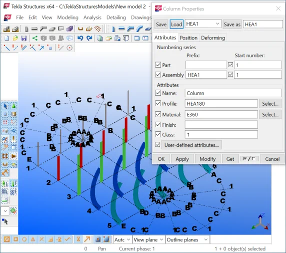
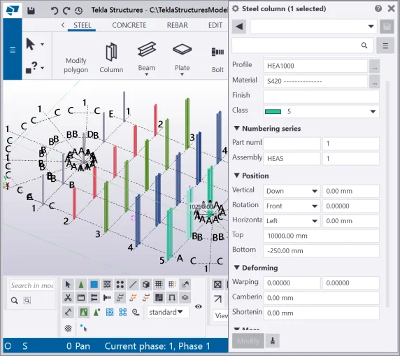
If it is required to export the pre-saved column settings to any other model, then go to the “Attributes” folder of the current model, which contains textual data of the saved sets of parameters. Each parameter set is defined by 2 files containing data about the basic attributes and user-defined attributes, and are described by the extensions *.CLM and *.CLM.MORE respectively. Copy the files into the new model’s “Attributes” folder, thus when opening the new model the copied sets of properties are available.
It is possible to read the copied files by any standard text editor. We will use these files when programming parameters and creating reports. Also, these files contain information about the names of the system parameters.
|
The list of files of the “Attributes” folder |
K1.clm file contents |
K1.clm.more file contents |
|
\\attributes\... \\attributes\... \\attributes\К1.clm
\\attributes\К1.clm.more
\\attributes\К2.clm.more \\attributes\К3.clm \\attributes\К3.clm.more \\attributes\К4.clm \\attributes\К5.clm.more \\attributes\... \\attributes\... |
encoding 1251 part_number_prefix "" assembly_number_prefix "К1" part_number_start_no 1 assembly_number_start_no 1 name "Колонна" profile "I25K1" material "С245" finish "" part_group "1" dx1 -250.000000 ….
|
column_attributes.REF_ID "" column_attributes.RENOVATION_STATUS -2147483648 column_attributes.IS_EXTERNAL -2147483648 column_attributes.FIRE_RATING "" column_attributes.SPAN -2147483648.000000 column_attributes.THERMAL_TRANSMITTAN -2147483648.000000 column_attributes.ACOUSTIC_RATING "" column_attributes.PITCH_ANGLE -2147483648.000000 column_attributes.COMBUSTIBLE -2147483648 column_attributes.SPREAD_OF_FLAME "" column_attributes.COMPARTMENT -2147483648 …. |
Find and open these files in any text editor and get familiarized with the contents. You can edit the files in the text editor. Saving the changes and reopening the model, updated the properties sets. Close the files.
User-defined attributes (UDA) represent a list of attributes to be specified by the user, which means it is possible to indicate various extra attributes by tacking on additional parameters fields and using them as required.
Attributes to be tacked on:
Every localization package (environment) is available on the UDA sets,
As a remark, note that all the Tekla Structures parameters can be divided
Example of b ringing out the UDAs to the properties menu in Tekla Structures v2021
Currently we will not use any of the UDA attributes. We will examine the
The main parameters defining an object are duplicated at the mini toolbar, which automatically appears when clicking on an object. We have already examined how to change the column’s position (reference line) using this toolbar, however, there are many other useful parameters located at the mini toolbar to be investigated. Despite the fact that various mini toolbar interfaces exist (depending on the TS version) the toolbar functionality remains the same.
It is important to mention that in the older Tekla Structures versions, the mini toolbar is not accessible if there are several TS versions launched simultaneously on one single PC. Also, in the older TS versions, the mini toolbar has a poor rendering, which stands for a hard recognition of the toolbar icon, due to its transparency.
By using the mini toolbar set up a different color of a column :
By using the mini toolbar change the column's profile value at D300, after at HEA500. You can type in any profile value from the keyboard or by using the profile catalog.
The mini toolbar is also available on the "Numbering Series" sub-menu defining the assemblies prefixes, parts prefixes, numbering starting values.
Clicking at the “Inquire object” button opens a dialog window with the description of the properties of the object, such as standard properties, orderly number of the part, weight, and other characteristics.
The alternative way of accessing the “Inquire object” report is as follows: select an object (column) and in the right-click menu proceed to the “Inquire”/ “Part” tab. Try out these two ways.
* Editing the “Inquire object” report is possible by using
The “Copy Properties” tool copies the set of properties of the selected object to another one.
The algorithm of using the tool is as follows:
The “Pin in place” button pins the mini toolbar and keeps it open/ expanded in case it is required to be used permanently.
The “Customize” button
Let’s add the “Finish” parameter icon to the mini toolbar
Check if the new element is added to the mini toolbar ribbon.
So far as we will not use the “ Finish” parameter in the following
Let’s examine in detail every “Column Properties” menu
The “Name” field
is a text field editable by users from the keyboard. By default,
this field is defined by the “Column” value. In case the vertical
segments created by the "Column" tool represent racks or any
other objects, the "Name" field can be manually edited as required,
as the TS does not automatically recognize the type of the object. Completing
this field is important, as its data constitute a part of reports, statements,
tables, and drawings.
The “Profile” field is a textual field as well, editable by users from the keyboard. On the right side of the field there is a button which gives access to the available profiles catalog.
Go to the profiles catalogue. Its contents vary from each other depending on the TS localization package in use.
Choose a different profile option, for example, HEM240.
The new profile name is automatically inserted in the respective
To apply the new profile type, press the“Modify” button. The “Modify” button updates the settings of all the selected objects according to the parameters’ values specified. If you select multiple objects, the “Modify” button simultaneously reconfigures the group of objects.
The “Material” field is also a textual field, editable from the keyboard. On the right side of the field there is a button which gives access to the available materials catalog.
Change the column’s material type to any random option. Do
not forget to press the “Modify” button to run the update.
The “Finish” field is not compulsory to be completed, but it allows mentioning any additional information about the object’s specifications. The "Finish" field may contain the following information: coating type, paint type, paint color, etc. It is important to highlight that this field affects the parts’ numbering. If two similar parts differ from each other only by the value of this field, the TS automatically considers these parts separate. We will get back to this attribute functioning later on. At the moment, leave the “Finish” field blank.
The “Class” field specifies the rendering color of the object in the 3D model. The range of available colors is enclosed between the code interval from 0 to 14. If you introduce a color code value greater than 14, e.g. 15, the TS automatically proceeds to the equation: 15-14=1, which final result defines the rendering color.
It is important to mention that color does not affect the numbering of the parts. If two similar parts differ from each other only by the class field, the TS considers them identical. The "Class" field facilitates visual distinction between various objects. Exercise editing the field values.
Examine the results in the 3D model.
The “Numbering series” and the “Part numbering”
fields
To get to the "Part numbering" field properties, let's,
Parts numbering and assembly numbering are two distinct numbering systems. Thus the identical parts may get arranged into a limitless number of various assemblies.
A number of a part consists of the prefix (it is optional for completing and is usually defined by textual characters) and the orderly number of the part.
If the "Prefix '' field of a part is blank, then the part
Tekla Structures automatically searches similar parts in the model and

As you can see from the above scheme, the parts numbering is as
Specifying the "Prefix" field value as “A”,

Applying the prefix value of “A” to the first group of objects, and value of “B” to the second group of objects, starts over the numbering process for both groups of objects.

Let's not apply any values to this field. Leave this field blank.
The “Start numbering” field
This field shall not be completed if there is no particular requirement to define its value. It determines the starting number of the numbering sequence of the parts. By default, it is set up at 1. Editing the starting number field value to 50 for group of objects defined by the “A” prefix value, updates the numbering scheme to as follows:

Considering the above, keep this fields’ default value.
The “Assembly numbering prefix” field
This field defines the numbering and marking of an assembly. If this field is blank, then the identical assemblies are numbered as follows: 1,2,3..n, which in practice is not quite convenient. Thus assembly prefix comes out as a useful tool and is defined as a short form of the assembly's name.
For example: Column - C, Beam - B, Vertical bracing - V, Horizontal bracing -H, Plate - PL.
Thus completing the “Assembly prefix” field determines the following numbering scheme: C-1, C-2, C-3... C-n which reflects the type of the structure in use.
|
The example of numbering scheme of assemblies defined by identical profile types |
||||
|
Assembly Prefix |
Column Profile |
Assembly name |
Number of assemblies |
SSD marking for each assembly (corresponding with the database drawing name) |
|
C |
HEB220 |
C olumn |
5 |
C -1, C -2, C -3, C -4, C -5 |
|
B |
I450 |
B eam |
5 |
B -1, B -2, B -3, B -4, B -5 |
If there is more than one profile type of the columns, then the assembly prefixes shall reflect these types in the following way: C1, C2, C3..Cn. This is the most commonly used numbering type. Thus each profile type shall be described by a distinct prefix.
|
The example of numbering scheme of assemblies defined by various profile types |
||||
|
Assembly Prefix |
Column Profile |
Assembly name |
Number of assemblies |
SSD marking for each assembly (corresponding with the database drawing name) |
|
C1 |
HEB220 |
C olumn |
5 |
C1 -1, C1 -2, C1 -3, C1 -4, C1 -5 |
|
C2 |
HEB280 |
C olumn |
5 |
C2 -1, C2 -2, C2 -3, C2 -4, C2 -5 |
|
B1 |
I450 |
B eam |
5 |
B1 -1, B1 -2, B1 -3, B1 -4, B1 -5 |
|
B2 |
I550 |
B eam |
5 |
B2 -1, B2 -2, B2 -3, B2 -4, B2 -5 |
The “Assembly numbering/ Start number” field
This field’s functioning is similar to the "Part numbering/ Start number" field. If the start number value equals “50” for the assemblies defined by prefixes C1 and C2, then the numbering scheme is as follows:
|
The example numbering scheme of assemblies defined by various profile types and a predefined start number value |
||||
|
Assembly Prefix |
Column Profile |
Assembly name |
Number of assemblies |
SSD marking for each assembly (corresponding with the database drawing name) |
|
C1 |
HEB220 |
C olumn |
5 |
C1 -51, C1 -52, C1 -53, C1 -54, C1 -55 |
|
C2 |
HEB280 |
C olumn |
5 |
C2 -51, C2 -52, C2 -53, C2 -54, C2 -55 |
|
B1 |
I450 |
B eam |
5 |
B1 -1, B1 -2, B1 -3, B1 -4, B1 -5 |
|
B2 |
I550 |
B eam |
5 |
B2 -1, B2 -2, B2 -3, B2 -4, B2 -5 |
Leave this field blank.
The “Cancel” and “Close” buttons are equivalent
The “Apply” button does not run any updates in the model. However, pressing this button defines the set of properties of the new object to be created. Thus we can conclude that the “Apply” button outlines the properties of the subsequently created objects but does not change the ones selected. In new TS versions, the values of the parameters are automatically retained at any update. The older TS versions are available on the “Apply” button with its standard functional, described above.
The “Ok” button closes the properties menu window and sets up as default the values of parameters for the subsequently created objects thus invoking the “Apply” button functional, but does not change the properties of the currently selected objects in the model.
The majority of the new TS versions are not available on this button,
The “Ok” button is most common for the older TS versions where it executes the very functional described above.
The “Get” button uploads the list of values saved in advance into the active properties menu fields. It can be similarly proceeded by executing a double click at a respective object.
The “Get” button is characteristic of the older TS versions. It is not available in the new TS versions, as the data is automatically uploaded upon a simple click on the object.
The “Modify” button executes changing the properties of the selected object according to the values of parameters. Editing the field values without recurring to the “Modify” button does not affect the object.
The older TS versions do not have any as-built feature of informing users if the “Modify” button is addressed without selecting any object in the model. If no object was selected, then addressing the “Modify” button gives no effect upon the model. Thus make sure that the required object is selected.
The new TS versions have the as-built function of keeping the “Modify” button inactive until any property's field value is changed for the selected object.
A column is just a vertical segment. In the current case study, the column’s reference line passes through the symmetry center of the I-beam.
There are 9 basic positions of the reference line in TS. Let’s examine an arbitrary shape to get a clear understanding of the reference line positions.
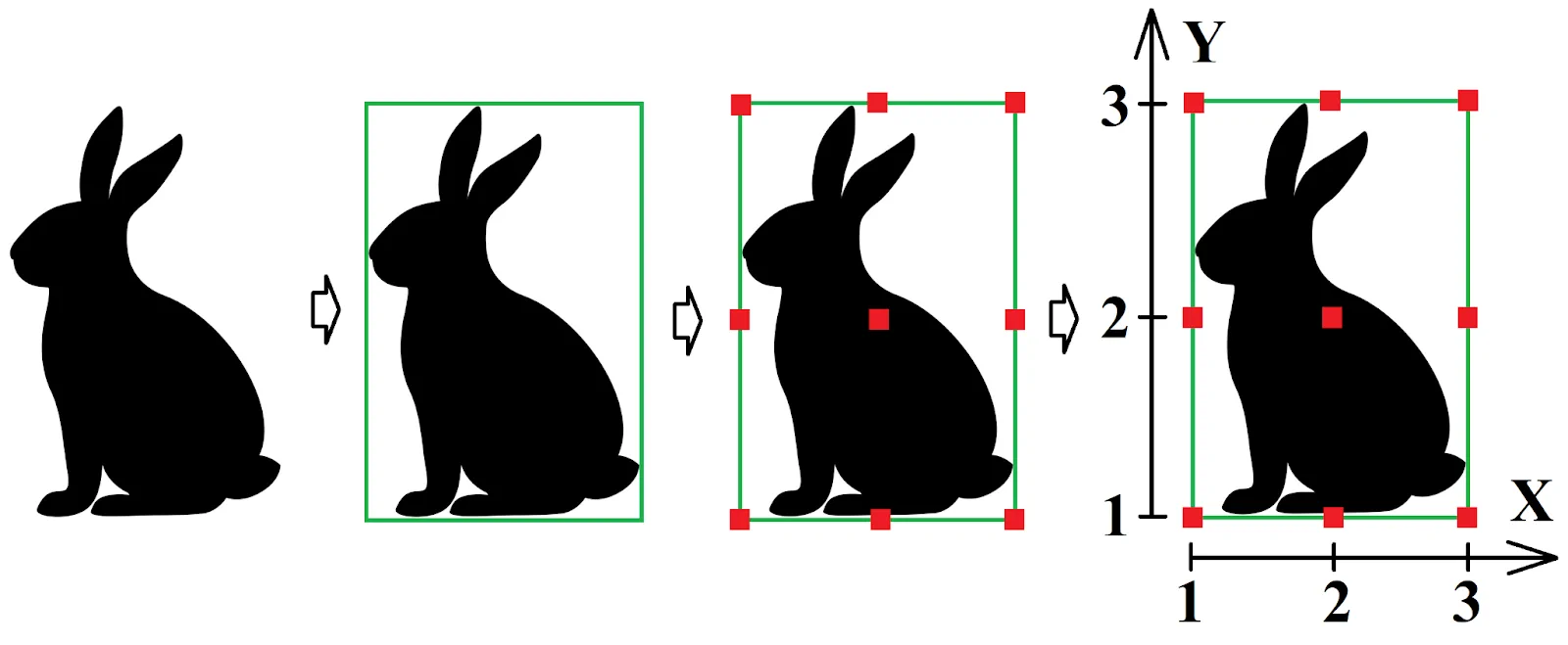
Let’s examine the above on the I-beam shape example:
As you can see, the coordinates of the column are centered at the point (2;2) defined by the axes X and Y. Please refer to the below picture:
The “Horizontal” position field (referring to the X-axis coordinates)
works similarly to the “Vertical” position field (referring
to the Y-axis coordinates).
Toggle between all the 9 (nine) possible reference line positions and see how the I-beam position changes in the model. Do not forget to select the I-beam column in the model and to press the “Modify” button subsequent to the position value set up.
Also, Tekla Structures is available on a “mini toolbar” which is useful for editing various values of parameters of an object. This toolbar is automatically popping up when selecting an object.
The toolbar ribbon is available on the "Position" switch, represented as a circle. Thus pointing to any sector of the circle (each sector corresponds to one of the 9 (nine) basic reference lines positions), or moving the green key point along the circle line, executes the position change. Exercise using the mini toolbar for changing the I-beam’s reference line position.
In the new TS versions the hotkey combinations of ALT+ arrow up, ALT+ arrow down, ALT+arrow right, ALT+ arrow left are switching the object’s reference line position.
Try out using these key combinations as well.
Pay attention that each "Position" field has an adjacent box next to it, used to define additional extension values for positioning the object with reference to an axis. The adjacent field values can be both positive and negative. In practice, these fields are rarely used.
Note that employing these fields is not recommended for moving the objects. Exercise positioning the I-beam’s reference line horizontally at the value of 500 mm. Compare your results to those presented below:
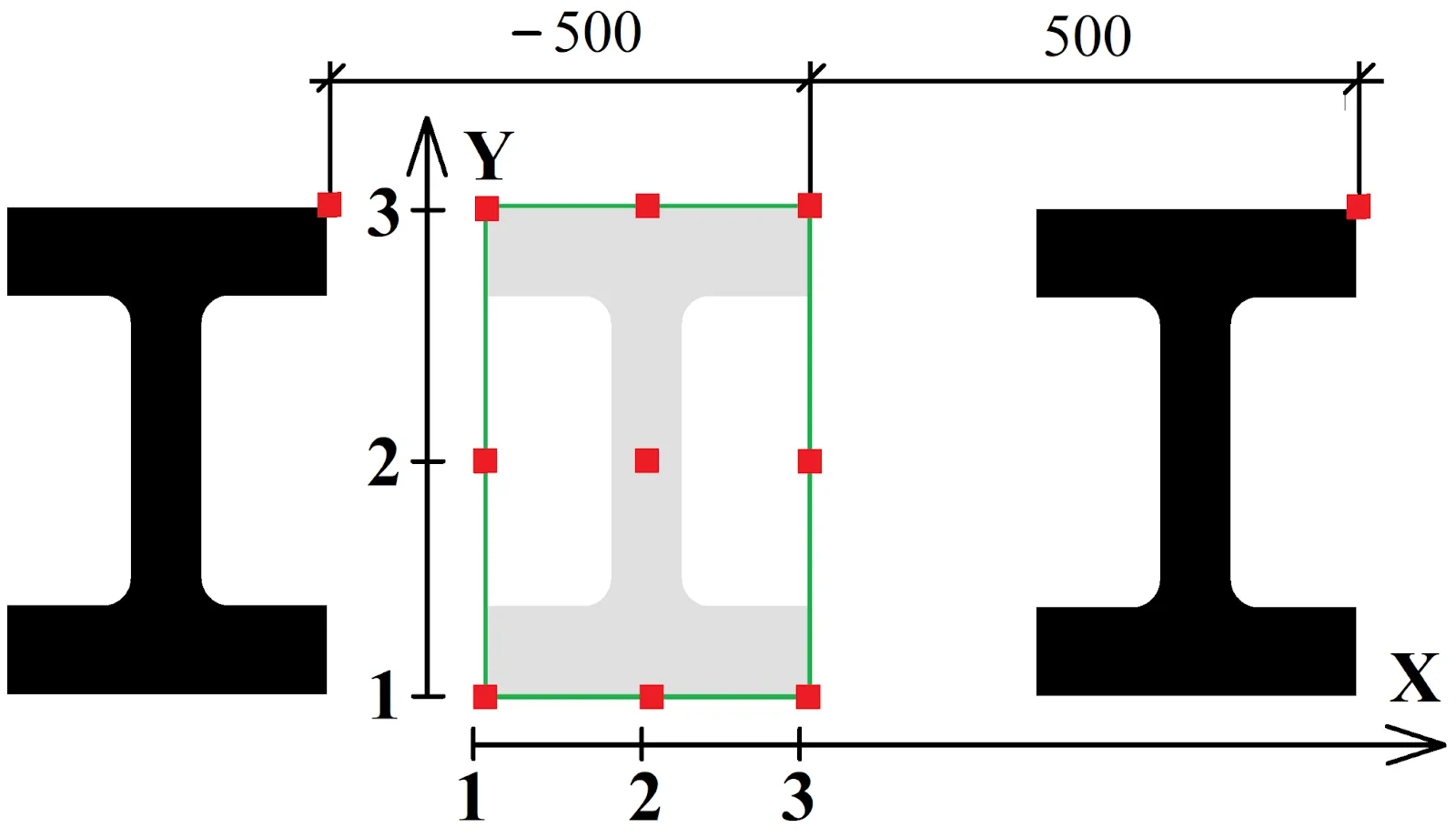
And now, proceed the same way by setting a negative value of - 500mm for the horizontal position parameter. Upon completion, restore the value of the horizontal positioning parameter to 0.
Let’s test the vertical positioning parameter value by setting it
Upon completion, restore all the values to 0.
The “Rotation” field
In the standard "Column Properties" menu, at the "Position" tabpage, there is the “Rotation” subfield which rotates an object around its reference axis.
The “Rotation” field is defined by the 4 (four) basic selectable options, each of them executing the +90 degrees turn, corresponding to the following values: 0, 90, 180, 270 degrees. Examine all the rotation options.
|
As a case study, let's create columns and allocate them along the grid perimeter as it is shown in the below picture. Also create columns at the center of the plan with the reference lines passing through the columns’ symmetry axis.
You should get results similar to the ones presented below. Now, switching the column profile type automatically modifies the visual representation of the objects, but does not affect the dimensions of the whole structure.
|
The “Column levels” fields
The “Levels” section fields specify the coordinates of the top and bottom points of a column in the global system of coordinates of a project. Let’s set the value for the bottom column level at -6000 mm. Check the model:
Now, set up the top level value of the column at +1000mm.
The "Deforming" tool is used for creating objects with complex geometry. Below you can see the example of a complex structure composed of warped and cambered columns.
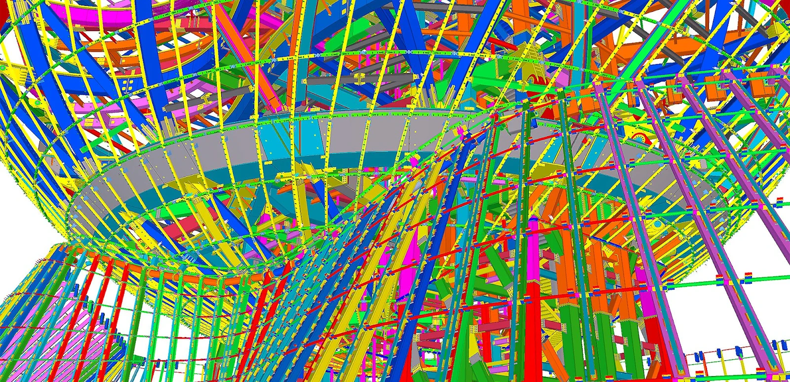
Go to the “Deforming” section of the “Column Properties”
menu. Note that all default values of the parameters are set at 0.
Let’s examine the subfields of the "Deforming" menu section. The “Warping” field coils a column in a spiral. By default, the warping value equals 0, but it can be set up to any value.
As we already know, each column is defined by a starting (marked in yellow)
The "Warping" field has two respective boxes for valuing these points. To warp a column from its up point downwards is realized by specifying the warp angle of the endpoint into the respective box, e.g. 30 degrees. Check it out.
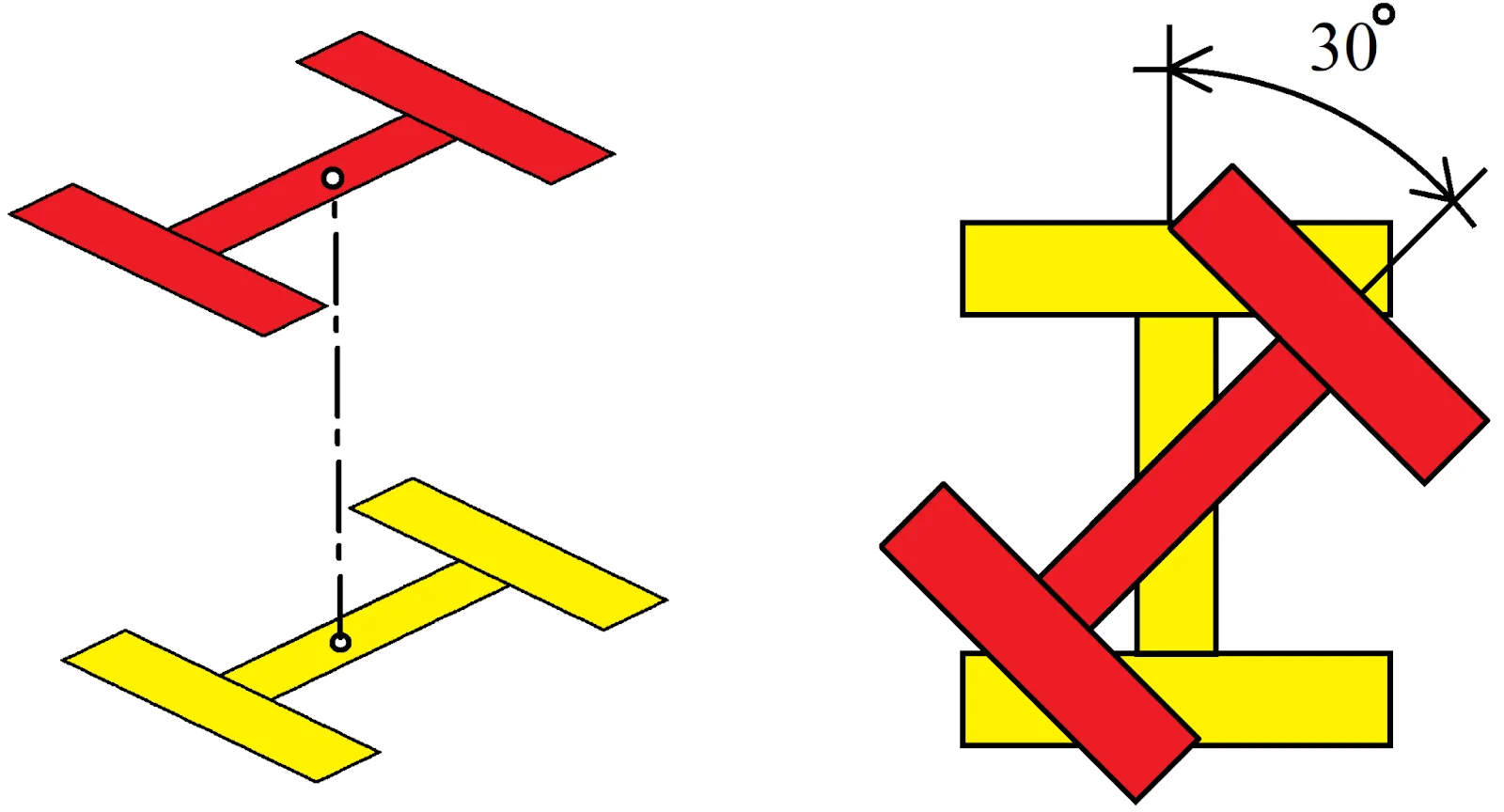
To warp the column from its endpoint, by leaving the column top side static,
specify the 0 value at the endpoint field, and the value of 30 degrees
at the starting point field.
Consider that indicating a warping value over 360 degrees coils the column in the numerous spins. In real practice, such examples are rarely met, except for mechanical engineering.
Try out editing the warping angle for the end column point.
Upon completion, restore all the “Warping” field values to 0.
The “Cambering” tool twists (curves) a column.
It is composed of two coherent basic parameters which make a column’s body cambered: the bending off parameter and the radius of the circumference on which the column is to be situated.
If the value indicated into the field is less or equal to one-half of the column’s length, then TS accepts this value as the bending off parameter, otherwise it automatically considers the value as the circle radius. The cambering direction is set up by indicating one of the symbols “+/-”.
|
Cambering value =0 |
Cambering value <= ½ column length |
Cambering value >= ½ column length |
Let’s exercise cambering a column by introducing a cambering value
In the new Tekla Structures interface the cambering field is not functioning.
However, uploading models created using previous TS versions may solve the issue and reflect cambered objects correctly, though modifying the uploaded data still remains impossible.
We do suppose that these fields are necessary for assuring compatibility with the older TS versions.
Now, set up the cambering value exceeding one-half of the column length,
e.g. 10000 mm. TS will automatically define it as a part of the circumference
length with radius of 10 000 mm, resulting from intersection of the circumference
with the initial column-bisecant. Compare your results to the below:
Restore the field values to their default settings. The “Shortening” tool is the one seldomly used. It simultaneously brings up different values of the same parameter into the statement and the drawing specification.
This tool is mostly applicable when modeling reduced plates.
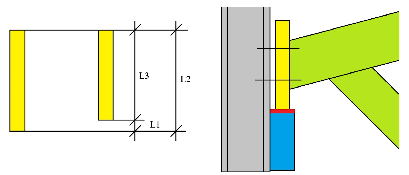
For example, a bearing plate is welded on to the formwork’s edge, thus it has to be reduced for obtaining a plane surface. Bearing surfaces must be critically plane (see marked with red in the above picture). That is why an already manufactured and welded-on component is additionally reduced, defining a decrease of the initial plate’s width value.
Exactly this fact brings up the issue of how to reflect the component in the drawing. If we draft the part with no concern to reduction, the geometry of the part intersects with the geometry of the structure.
If we reflect the part with its reduced thickness value, the statement for manufacturing pre order indicates the dimensions of the part without considering the allowance for reducing, thus the manufactured component is too low.
Such wise the "Shortening" field specifies the thickness of
the bearing plate prior to reducing, indicating the value to be included
into the preorder report, and at the same time, it reflects the thickness
of the bearing plate to be reflected in the drawing.
|
Shortening (L1) |
Component dimensions at the drawing (L2) |
Component dimensions included in the preorder report (L3) |
|
0 |
5500 |
5500 |
|
1000 |
5500 |
4500 |
|
-1000 |
5500 |
6500 |
Exercise introducing various values into the "Shortening" field,
e.g. 1000 and -1000. Note that the geometry of the model does not
change after executing shortening, but when selecting the object, the TS
displays different values of the dimensions of the objects at the drawing
and in the statement.
The allowance for reducing is defined by the range of 2-6 mm and depends on various factors. Thus in the report it is reasonable to indicate the thickness value considering the allowance for reducing, as the abatements from the drawings can be fixed outright at the construction site.
Upon completion restore the field values to their default settings.

